In this article I have explained how to build a highly efficient voltage regulator circuit using an SCR and some other external components.
This SCR voltage regulator circuit being a switching kind of regulator is more efficient than the normal 3 pin voltage regulators, or the transistor zener based series pass regulators circuits.
How the Circuit Works
The following figure exhibits the circuit of an SCR based regulated power supply. The only parts necessary for the regulation process are the SCR, R1, and the zener. When power is first switched on, the filter capacitor C1 is in the discharged condition such that its cathode is at 0 V potential.
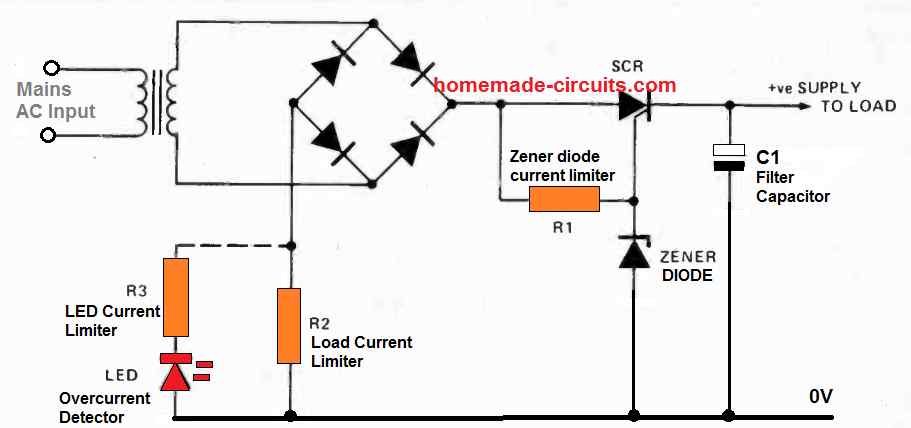
The positive half cycle waveform going out from the bridge rectifier causes the gate current for the SCR to pass through the resistor R1, which triggers ON the SCR. As soon as the SCR switched ON it starts charging the C1 filter capacitor. When the positive half - cycle ends the SCR quickly turns OFF.
As soon as the next positive half cycle arrives from the bridge, the same process repeats, charging the filter capacitor C1 until the voltage has almost reached the zener breakover voltage. As we can clearly understand, the maximum positive voltage that can arise at the gate of the SCR gate is established by the zener value.
Therefore, it means, during the above process a time comes when C1 is able to charge only up to the zener level beyond which the SCR gate is unable derive anymore positive potential, with reference to its cathode. At this specific stage the SCR is unable to sustain its firing anymore and C1 cannot charge any further.
The filter capacitor C1 discharges through the load, using the amount of power supplied from the transformer. The moment the next positive cycle arrives the SCR gate turns yet again positive, and fires, charging the C1 filter capacitor.
A couple of half cycles from the bridge are enough to lift the C1 voltage adequately to stop additional firing of the SCR. As a result the SCR triggers as essential to maintain the C1 capacitor in the "topped up" condition.
How many times the SCR has to trigger specifically depends on the current rating of the load which is being consumed from the input supply.
High Efficiency Output
You will find a couple of notably interesting characteristics of this type SCR based voltage regulator circuits.
Firstly the circuit provides a high degree of efficiency due to minimal power loss that are commonly found in either the series or the shunt type regulators.
The second great feature is that you are able to get a quick indication of the current that's being consumed by the load.
The second feature could be implemented by hooking up a LED in series with a limiter resistor R3 across the resistor R2, which acts like the load current limiter.
The LED will start blinking whenever the SCR triggers and therefore the blinking rate of the LED will directly correspond with the load current and indicate if the load has exceeded the current limit.
Parts List for 1 Amp SCR Power Supply
- Transformer = 0-12V/1 amp
- Bridge Rectifier = 1N5402 x 4 diodes
- SCR = C106 (on heatsink)
- Zener Diode = As per the required output voltage
- R1, R2 = 1 K 1/4 W
- R2 = 3 Ohm 3 watt