In this post I have explained a simple IC 555 based self optimizing solar battery charger circuit with buck converter circuit that automatically sets and adjusts the charging voltage in response to the fading sunlight conditions, and tries to maintain an optimal charging power for the battery, regardless of the sun ray intensities.
Using a PWM Buck Converter Design
The attached PWM buck converter ensures an efficient conversion so that the panel is never subjected to stressful conditions.
I have already discussed one interesting solar PWM based MPPT type solar charger circuit, the following design may be considered an upgraded version of the same as it includes a buck converter stage making the design even more efficient than the previous counterpart.

Note: Please connect a 1K resistor across pin5 and ground of IC2 for correct functioning of the circuit.
The proposed self optimizing solar battery charger circuit with buck converter circuit may be grasped with the help of the following explanation:
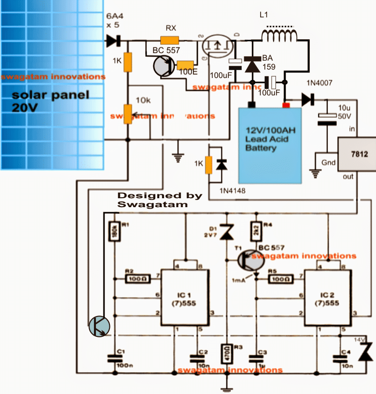
The circuit consists of three basic stages viz: the PWM solar voltage optimizer using couple of IC 555s in the the form of IC1 and IC2, the mosfet PWM current amplifier and the buck converter using L1 and the associated components.
IC1 is rigged to produce a frequency of about 80 Hz while IC2 is configured as a comparator and PWM generator.
The 80 Hz from IC 1 is fed to pin2 of IC2 which utilizes this frequency for manufacturing triangle waves across C1.... which are further compared with the instantaneous potentials at its pin5 for dimensioning the correct PWMs at its pin3.
The pin5 potential as may be seen in the diagram, is derived from the solar panel through a potential divider stage and a BJT common collector stgae.
The preset positioned with this potential divider is initially appropriately adjusted such that at the peak solar panel voltage the output from the buck converter produces the optimal magnitude of voltage suiting the connected battery's charging level.
Once the above is set rest is handled automatically by the IC1/IC2 stage.
During peak sunlight the PWMs get appropriately shortened ensuring minimum stress on the solar panel yet producing the correct optimal voltage for the battery due to the presence of the buck converter stage (a buck boost type of design is the most efficient method of reducing a voltage source without stressing the source parameters)
Now, as the sun light begins diminishing the voltage across the set potential divider also begins to drop proportionately which is detected at pin5 of IC2....on detecting this gradual deterioration of the sample voltage IC2 begins widening the PWMs so that the buck output is able to maintain the required optimal battery charging voltage, this implies that the battery continues to receive the correct amount of power regardless of the sun's retarding illumination.
L1 should be dimensioned appropriately such that it generates the approximate optimal voltage level for the battery when the solar panel is at its peak specification or in other words when the sunlight is in the most favorable position for the solar panel.
RX is introduced for determining and restricting the maximum charging current limit for the battery, it may calculated with the help of the following formula:
Rx = 0.7 x 10 / Battery AH
How to set up the above self optimizing solar battery charger circuit with buck converter circuit.
Suppose a 24 V peak solar panel is selected for charging a 12 V battery, the circuit may be set as instructed below:
Initially do not connect any battery at the output
Connect 24 V from an external C/DC adapter across the points where the solar panel input is required to be fed.
Connect a 12 V for the IC1/IC2 circuit from another AC/DC adapter.
Adjust the potential divider 10k preset until a potential of around 11.8 V is achieved at pin5 of IC2.
Next, through some trial error tweak and optimize the number of turns of L1 until a 14.5 V is measured across the output where the battery is required to be connected.
That's all! the circuit is now set and ready to be used with the intended solar panel for getting an optimized highly efficient PWM buck based charging procedures.
In the above self optimizing solar battery charger circuit with buck converter circuit I have tried to implement and extract an oppositely varying voltage and current output from the the circuit with respect to the sunlight, however a deeper investigation made me realize that actually it should not be responding oppositely rather corresponding to the sun light.
Because in MPpT we want to extract maximum power during the peak hour while also ensuring that the load does not hog the panel and its efficiency.
The following revised diagram now makes a better sense, let's try to analyze the design quickly:
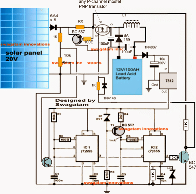
In the above updated design I have made the following important change:
I have added a NPN inverter at pin3 of IC 2 so that now the PWMs from IC 2 influences the mosfet to extract maximum power from the panel and reduces the power gradually as the sun light diminishes.
The PWM pulses along with the buck converter guarantees a perfect compatibility and maximum power extraction from the panel, but diminishes gradually in response to the sun's diminishing intensity.
However, the above set up makes sure about one important aspect, it ensures a balanced input/output power ratio which is always a key issue in MPPT chargers.
Further if in case the load tries to extract an excessive amount of current, the BC557 current limiter immediately comes into action preventing the disruption of the smooth functioning of the MPPT by cutting off power to the load during those periods.
Update
Contemplating the Finalized Design of an MPPT Circuit
After going through rigorous further assessments, I could finally conclude that the second theory discussed above cannot be correct. The first theory makes more sense since an MPPT is meant solely to extract and convert the extra volts into current that may be available from a solar panel.
For example suppose if the solar panel had 10V more than the load specs, then we would want to channelize this extra voltage to the buck converter through PWMs such that the buck converter is able to produce the specified amount of voltage to the load without loading any of the parameters.
In order to implement this, the PWM would need to be proportionately thinner while the sun was at the peak and releasing the extra volts.
However, as the sun power diminished, the PWMs would be required to broaden so that the buck converter was continuously enabled with the optimal amount of power for supplying the load at the specified rate regardless of the sun intensity.
To allow the above procedures to happen smoothly and optimally, the first design appears to be the most appropriate one and the one that could fulfill the above requirement correctly.
Therefore the second design could be simply discarded and the first design finalized as the correct 555 based MPT circuit.
I did not find it appropriate to delete the second design because there are various comments that seems to be linked with the second design, and removing it could make the discussion confusing for the readers, therefore I decided to keep the details as is and clarify the position with this explanation.
Have Questions? Please Leave a Comment. I have answered over 50,000. Kindly ensure the comments are related to the above topic.
Good evening sir, I have a 96v panel up on my roof, I have bought many controller but without any gain. I want to use the above design, pls I want you to house me on what to do thanks. Johnson
Hello Johnson,
The the above circuit can be difficult to optimize unless you are an expert in this field, therefore I would suggest you to buy an SMPS circuit which are designed to work right from 85 V onward. The output can be as per your required specification, either 12 V or 24 V.
Hello sir, please can i use air core inductor , i couldn’t get ferrite core, if yes how, if no any alternative. thanks
air core will not work, you cannot modify anything in the circuit
Good day sir, i have completed the circuit, which point will i connect the 12v adaptor to set IC1/2 to set it
Hi Pelumi, connect +12V where 7812 connection is connected.
keep pin3 disconnected initially and pin5 from the BC547, test the pin3 pwm by supplying a 0-12V varying input to pin#5 from an external power supply
well done sir, pls can i replace ba159 with in5408, i couldnt get ba 159 diode. thanks
thanks pelumi, no you can’t, because 1n4007 is not a fast recovery diode…you can try any other fast diode such as FR107 etc
Dear Mr. Swagatam,
in order to increase the maximum current switchable by your circuit (5 amps to 10-20 amps), do I only have to buy a larger inductor rated for 20 amps, or do I have to do change something else in your circuit?
I really want to thank you for your great work and support!
Best regards, Sebastian
Dear Sebkov, yes upgrading the inductor should be enough, assuming that the mosfet is already capable of handling that much current.
the inductor specs and the PWM are the two factors that are responsible of determining the current at the output, and ofcourse including the output filter capacitor.
Hello Mr Swagatm thank u agian for ur circuit I just want u to know it is still working fine Sir allowing the panels to work at a better wattage. Keep up the great work Alex. Any more new sine wave circuits please send me a link if there is any sir.
Hello Mr. Alex, thank you so much, I am glad that my concept is working for you and helping you with the desired results.
You can also check out the following article for getting an updated version of the same:
https://www.homemade-circuits.com/2015/11/simple-solar-mppt-circuit-part-2.html
Thank u Mr Swagatam for the design link I will build another one like this and see if it works like ur first I have sir. please remember to send me if any new links on sine wave inverter in ur blog. Thank u
sure Alex, wish you all the best, and keep up the good work
Hello Mr. Swagatam, I am total newbie in electronics – I even hesitated before asking, however I would like to try building this circuit. It does what I would like my solar controller to do – charge 12V battery when there is not enough sun to produce 13.8V. I exactly need it for 20V panel (producing 0.3A in peak sunlight) to charge 7.2Ah sealed lead-acid battery.
The best option for me is to buy a ready circuit somewhere. Could you please tell me sir if this circuit is available for ordering? If not then I will try to make it myself. I have bought Chinese solar controller from ebay, but it is not performing well, so I hesitate to buy from ebay again. I realize it will not be easy to build, but if I get all needed components then soldering should be the easiest part.
First I created a list of all items used in your circuit:
2 x BC 557 [PNP BC557BBK] (T1)
1 x 2V7 2.7V-3V zener diode (D1)
1 x BA 159 (1000V 1A)
2 x 1K
1 x RX (I will use 7.2Ah, so it should be 1k resistor according to given formula)
1 x 10k
1 x 180k (R1)
2 x 100R (R2, R5)
1 x 2k2 (R4)
1 x 470R (R3)
2 x 100uF
1 x 1u
1 x 10u 50V
2 x 10n (C2, C4)
1 x 100n (C1)
1 x L1 (trial & error: 20 turns, 1mm super enameled copper wire over a 1 cm thick ferrite rod)
1 x 1N4007
1 x 1N4148
However following requires some more explanation:
5 x 6A4 (6A 400V) – I was not able to find all 5 rectifying diodes mentioned in the circuit drawing.
1 x 14V (there is some zener diode at bottom-right which states 14V – is it 14V zener diode?)
1 x ??? (there is a NPN transistor bottom left – what parameters should it be?)
1 x switch (there is some switch at the middle top in a circle marked with C, 2 and D – what it is?)
1 x 100E (is it a resistor? 100 ohms?)
1 x 7812 (I suppose it is voltage stabilizer, is any specific parameter needed or these will do? – L7812ABV, L7812CV-DG)
2 x IC (7)555 (IC1, IC2) – will this timer suit? – COM-09273
I will highly appreciate your response sir!
Hello Ronalds,
the above circuit is a buck converter based MPPT, meaning it will optimize power from a high voltage panel, but if the panel voltage is low this circuit will not perform….
for example it will convert an input power of 24V x 1amp to probably to 14V x 1.71 amps for a 12V battery…but if the panel volt drops to 11V it will not respond.
moreover this circuit not for a newbie, because there could too many adjustments and tweaking which might need an experts knowledge, so it may not be recommended for you..
Sorry a ready made kit is not available from my side.
Good sir.
I need simple solar charging controller circuit diagram that can charge solar battery 12volt 100A.
Thanks.
Your blessed
You can try this:
Solar Panel Voltage Regulator Circuit
Hi, I have 40A PWM solar charge controller. I would like to make a 40A mppt solar charge controller, instead of that, can I use a 40A Buck converter output to the existing 40A PWM charger. So that it will work as MPPT. Is it correct? Please share the diagram and components details.
a buck converter is designed to reduce voltage and increase current for a particular load…so what is your load here? example if your input is 12V and you want to charge a 5V battery then a buck converter can be used
Hi Swagatham, I have a 12V, 40A pwm charge controller and I would like to make a 40A buck converter to supply the 15V 40A to the PWM charge controller. Can you please share the required components details and diagram.
Hi Kumar, I am sorry I could not understand your requirement, I think you might have missed something…
What's the function of bc557 and 2.7v zener in pwm pulse generator. Sir irf9540 is not available in our area can u suggest some other MOSFET for the circuit. Shall I use tip 122 instead of MOSFET. Sir I purchased all the components now I am waiting for your reply
BC557/2.7V zener are for providing a constant current for the triangle wave generation so that the PWMs don't get affected at lower voltages.
You can replace the mosfet with a TIP127 (5amps) or TIP147(15 amps) NJTs.
make sure you understand the whole concept thoroughly before attempting it. An researched version of the above is submitted here:
https://www.homemade-circuits.com/2015/11/simple-solar-mppt-circuit-part-2.html
Sir. Shall I change the above buck converter into a buck boost converter in such a way that it should act as a buck converter at peak time more sunshine time and it will act as a boost converter at evening time I hope that due to this arrangement we can charge a battery for long period of time and also that we can convert the extra voltage in peak time into current
Vijay, I don't think the would be effective, because in the evening the current from the panel will also become significantly low which cannot be used for boosting and charging the connected battery…the concept I have explained below is the only way to get the most effective MPPT result
https://www.homemade-circuits.com/2015/11/simple-solar-mppt-circuit-part-2.html
Hi Swagatam,
Small correction in my reply. I removed the mosfet from the ckt and checked. It is in good condition.
Later I learned that PWM works in the same way, it brings down the solar panel voltage down to battery voltage with power loss. That's why good heat sink is required. On the other hand MPPT maintains power all through the charging phase. 🙂
I have purchased 30 A MOSFET today, will try that and let you know about heating problem.
Thanks again.
Hi Manjunath, if you don't have an inductor (coil) in your circuit, then it cannot be an MPPT or a buck converter based circuit.
and without an inductor your circuit cannot bring down the solar voltage with an MPPT efficiency.
so make sure it has includes an inductor…
…I am sorry Sham, I used the wrong name, please ignore it.
Yes you are right Swagatam. Mostfet is gone bad. I see low resistance between all three terminals.
I don't get irf9540, but can arrange irf4905 and try.
No am not using buck converter… I guess it is for powering mcu you mean…
I refered this link for my mcu pwm.
m.instructables.com/id/ARDUINO-SOLAR-CHARGE-CONTROLLER-Version-20/
Sham, sorry but you cannot check and confirm a mosfet with an ohm meter…
Hi Swagatam,
I have rigged up simple P channel PWM charger ckt. I use MCU to control the duty cycle. To be frank, i blindly followed the ckt without understanding it. But its working fine on the first attempt itself, of-course after burning few mosfets. Later added heatsinks to both diode and mosfet.
I have gone through most of the PWM/MPPT chargers you have posted to understand the need of P channel or N channel mosfet.
1. Could you please tell me which is the best type of mosfet to use? N or P channel?
2. If i have to charge a 150 AH battery at C/10 rate, what is the current rating of the mosfet that i need to use? I know that any thing higher value would do but i need to understand the calculation(thumb rule).
3. During charging, if battery voltage is 12.45v My panel voltage reads 13.36 v. and current is at MAX 10.4 Amps. Is it normal? Shouldn't the panel voltage be 19.5 V? (i have 100W x 2 nos connected in parallel)
I hope you will help me in understanding this. Thanks in advance.
Hi Sham,
If the mosfet is getting too hot, and the panel voltage is dropping then your circuit is seriously NOT working…it is in fact doing the opposite.
I don't know whether you used a buck converter or not, but with a buck converter the mosfet is not supposed to get hot and the panel voltage is not supposed to fall below its normal working range.
P or N both are equally good depends on what kind of input is fed…P will respond to negative triggers, and N to positive triggers.
mosfet current rating for a 150AH battery charging could be around 25 Amp t 30 amps….a IRF540 or IRF9540 would do the job
thank u Mr Swagatam i have read the link sir and see it is a trial and error method to determine the right coil. Just a question sir as in our case we have a changing pwm with sun light so would this affect our setting the right frequency to determine the right coil in our mppt sir Alex
Thanks Mr.Alex, changing PWM will not affect the frequency, frequency will always be constant and stick to the original value.
By the way you can also refer to the following updated article:
https://www.homemade-circuits.com/2015/11/simple-solar-mppt-circuit-part-2.html
thank u mr Swagatam i just saw the two articles on buck converter could u send me the last link on the topic sir thank u Alex
Mr Alex, here's the third link:
https://www.homemade-circuits.com/2015/10/calculating-inductor-value-in-smps.html
by tomorrow you may see the new finalized article on MPPT published.
hello Mr Swagatam any thing new on the mppt sir Alex
Mr. Alex, everything is crystal clear now after those three consecutive articles on "Buck", "boost" and "calculating buck inductor" which I posted recently after an exhaustive study…the end formulas have cleared all my doubt and helped me to conclude that the first circuit is indeed the correct one…Ill be soon presenting the details comprehensively through a new article.
yes sir we are always here learning from ur posts
Thanks Alex, you can read the following couple of posts for understanding buck converters:
https://www.homemade-circuits.com/2015/10/how-buck-converter-works.html
https://www.homemade-circuits.com/2015/10/calculate-current-voltage-buck-inductor.html
more will be coming soon.
thank u sir please let us know when this is posted because we all need to get this to work right ALEX
sure alex, please stay tuned
Hello Mr Swagatam i think also the frequency we use maybe should have something to do with the buck converter coil we use but as u say let us see Mr Tonybens design Alex
Hello Alex, higher frequency will allow lower number of turns, and vice versa.
I'll soon be presenting a new article explaining how to design a buck converter coil.
Thank u Mr swagatm I will rewind and let u know sir Alex
Mr. Alex, I would want to change my view yet again, this may look irritating but associating PWM with an analogue stage can be quite confusing, and not easy to simulate the results quickly in mind, and that's why I have to go through fluctuating judgements.
The second design is what you must follow, but also include an effective error amplifier with it, I'll try to update the final design soon…please bear with me.
Hello Mr Swagatam, is good to know you change your judgment in favour for the second circuit, as i have maintain previously to be the option closest to mppt. I have been working on the back ground to implement a true mppt. i have simulated that circuit i shared with you and the result was as i expected it. Now i am implementing a true mppt with PIC controller.After much research on mppt controllers i found out that its even much easier to implement it with micro controllers.than any other means. Mppt is quite an exciting control system. when am done i will share all finds.
thanks Tonyben, however I am still not in a position to give a finalized viewpoint, since I am still struggling with the optimization results of the inductor with reference to the varying solar panel voltage, the switching time (PWM) and the current with reference to the frequency. unless these are correctly calculated things can get utterly wrong.
Even with a microcontroller you would need to calculate all these parameters for the correct results.
Hello Swagatam, You are right every parameter needs to be calculated to get the desired results.
with our second circuit diagram in this article we need to calculate all the parameters for buck converter stage. choose a switching frequency, max current output and allowable ripple current. With these parameters we calculate the required inductor value. The second circuit is quite impressive in regulating extracted power if calibrated well. E.g assume there is constant (irradiance) sun shine and we attach a load lager than the solar power.The load will tend to hug down the panel voltage, as the panel voltage drops due to much load, the Pulse width(pwm) automatically reduces,this reduces the the output current to the load. As the load current drops the panel voltage increases again, this circle continues until equilibrium is attained which will be roughly at the available solar panels wattage. So at any point in time the available solar power is what the load can get. Yes, an error amp can be added to the output to maintain a safe max voltage for the battery at all time. The second circuit approach is truly an mppt though not as precise like a micro base one but it performance is amazing when calibrated properly. I can share my circuit approach if required.
Hello Tonyben,
You are always welcome to share your MCU circuit, folks will surely appreciate it.
However I am a little confused with your assumption regarding the second circuit.
What you have explained is supposed to be the function of an error amp which is not yet included in the design. This is not how the the 555 section is designed to operate.
The 555 section is designed to detect the diminishing sun light and either decrease the PWMs, or increase it depending upon how it's configured with the switching transistor.
The above is the one aspect, the other aspect is how the buck converter functions.
I have just now published one article which you can refer through the following link:
https://www.homemade-circuits.com/2015/10/how-buck-converter-works.html
If you see the solved example at the bottom section of the page, you will see that it's the PWM or the transistor switching time which solely affects the buck voltage.
After reading this we may want to change our decision and once again think about the first circuit above as the right MPPT circuit for loads which may be lower than the panel output.
Hello Swagatam,
No we dont have to change our decision in favour of the first circuit. Let me explain even with the buck article you just posted. The first circuit can NEVER never track mppt as long as it gives wider pulses with diminishing sun intensity, this seems contradictory looking at the buck stage attached to it.But let me explain,
The goal of the total circuit is to give out an output power that is close to input power from the panel at all times.
If you check back at my post on 9th of june 2015, which was basically stating the same thing the bulk converter article you posted is stating "that inductors in converters are energy storage mediums and that the switching pulse width(pwm) determine the output voltage stage of the converter.
With the above said and understood lets look at our first circuit in line with the the bulk stage converter at it's output stage.let make some assumption here: assume a solar panel 100w with 20voc. So our Imax= 5A. our duty cycle needs to be above 0.6 to be able to charge a battery load.
Lets look at two scenario. 1: constant sunshine and 2:diminishing sunshine.
Scenario1:
If we place a single battery load that pulls 100w of power, everything will be fine since load is within solar panel available power. so output current will be about 8A, assuming 12v output. if we double the load by placing two baterry which will be 200w of load.Now this is where the issue comes.this load tends to pull all 200W from the output but our panel can only deliver 100w, this overload pulls down the solar panels voltage, because the panel max current Imax is 5A, trying to pull 10A is like short circuiting the panel.This drop in the panel voltage increases the duty cycle of the pulses base on the first circuit, this increase is suppose to increase the output voltage but our input voltage is down already any increase in our output voltage will only further load down the solar panel.so in effect the panel voltage may fall to a value of say 12v, becasue panel Imax cannot ecceed 5A in our case, our panel will be outputing 60W instead of 100W 40W lost.
A typical mppt if faced with overload will reduce pulse width to cutdown on demanded power to what it can deliver.
Scenario 2:
if we have deminishing sunshine which leads to lower panel voltage and lower available panel power. the bulk converter output voltage falls due to this deminishing sunshine (Vo= VinD). Our pulse width increase to increase the outputvoltage to our 200w load.This 200W load poses much more overload to the solar panel because there is even less than 100W of avaible power from the panel. So increasing the the pulse width in this case still futher overloads the panel and making it never to operate at the MPP.
So you can see in both scenario even though we have a bulk converter with increasing pulse width as the sun diminishes, it does not lead to max power tracking.
However if we look at the second circuit approach in both scenario it behaves like i explained in the previous post before this one.
You mentioned that my previous explanation was as if there was an error amplifier in the second circuit, no there is none.But in effect that is how the circuit behaves because it gives out smaller pulses with reducing panel voltage.
if the load is too much that it pulls down the panel voltage the pulse width is reduced to cut down the demanded power to a level that it does not affect the panel voltage much( mppt).
It is very easy to prove which one of both circuit is true mppt by putting an same overload on both circuit and see which one gives out more power.
I encourage people to try it do that simple test you will be amazed.
If you build the circuit with all parameters calculated you will see that the result is self evident.
Although in my approach like the circuit i once shared with you i used the ramp from the 555 and compare it with a reference from the solar panel.
The output of the comparator is what generates my switching signal.So i have just one 555 timer.
I repeat, the second circuit appraoch is an awesome mppt if calibrated properly.
Hi Tonyben,
Thanks for the detailed explanation.
However, an MPPT is not about adjusting an overload, an overload control or a short circuit control is the job of an error amplifier, which I have tried to include in the form of the BC557 just beside the mosfet.
The role of MPPT is to maintain the V x I ratio constant even while the sunshine is dropping.
Initially we have the high voltage from the panel on our favor, so we use a narrower PwM because we already have extra power in the form of higher voltage.
Even with the narrow PWM we are able to convert the extra voltage into current and maintain the V x I product constant.
Now when the sun shine goes down, the voltage drops, so to compensate this drop in voltage the PWM is increased so that the buck converter can sustain its output power…this situation goes on until the sun shine has dropped below the maintaining limit.
I'll try to present the scenario with more clarification in the article, and request you all to decide whether or not it's justified and correct.
Hello Swagatam,
In a sense you are right in saying MPPT is not about adjusting an overload. I use an overload scenario to paint the picture clearer.But also look at it this way. if the available power on the panel falls due to diminishing sunshine and the battery load on the controller at that point is greater that the panel power, that is an overload situation.And this situation is what happens all the time with a solar panel. And this is the main reason an mppt is required to match the load to the solar panel for maximum power transfer. Secondly note as long as we have more power on the panels than the load there is actually no mppt because the output power can not be more than what the load demands. So technically speaking mppt only takes when the load power in greater than the input power(solar panel).
Hi Tonyben,
according to me MPPT is supposed to handle the V x I value and make it stays constant across the panel and the load all the time during day, it does not supposed to have any other role to play. The overload condition is supposed to be monitored and controlled by the error amplifier.
If one succeeds to implement this in an MPPT circuit then I think the mission would be completed.
thank u Mr Swagatam for ur reply . My circuit is still working so far so good as a panel optimiser. I had asked in my email if u could tell me roughly about how many turns i should use on my buck converter coil in that I was using a 48v system and u had design the circuit for 12v Sir. I think I should be using more turns I now have about 12turns. I await ur reply . Thank u Alex
Mr. Alex, yes, the rule of thumb is that the coil may generate at the rate of approx 1V per turn….so to acquire 48v you may incorporate around 50 turns for the buck converter
ok Mr Swagatam I know u will fix the problem for us. My panel optimiser as u call it now is still working as one alowing the panel to work at a higher wattage. Please post the update here as soon as u do the improvement. Thank u for ur support to us ur readers and keep up the good work sir ALex
sure Alex, thanks, I'll try to do it soon.
Hello Mr Swagatam long time dont make a link but I am working behind the senes on the sinewave inverter . The filter is my biggest problem so i am doing trial and error on this sir. I want to know if u have designed any other mppt circuit as yet that have over come the problem of the one above if u have please send me the link sir thank u and keep up the good work Alex
Hello Mr. Alex,
as for the MPPT circuit, the first design in the above article is the final and the perfect one, I can say this after going through a deep contemplation and analysis….if even includes the error amp in the form of the BC557 current controller…so it's the ultimate MPPT controller which you can rely on.
the filter circuit is something which will need to be confirmed with trial and error, I have no idea regarding the calculations so far, since I have not yet researched it….
Hello Mr Swagatam any improvement on the mppt controller yet sir Alex
Hello Mr. Alex, I am quite sure now that PWM cannot be used for producing a smooth varying DC, so it's an error amplifier that must be employed for ultimately regulating the desired voltage from an MPPT.
I could not update the article yet…but it's just about adding a error amp to the above circuits for finalizing the MPPT design
ok Mr swagatam we just wait until u gete the time because I know u will be coming with the answer
sure Alex, thanks!
I will definitely share all my details here as i progress with the work. if Alex would not mind could you also share those mppt circuit with me?.
I try to forward the material to you, soon…
Hello Swagatam, please can you help me with part number of any schottky diode with a forward current of at leat 10A, I want to implement the mppt using the approach of the of the schematics i showed you, I will be employing the CUK topology for my converter stage since it can give a greater output voltage than the input voltage which will be converter to current at a fix out put voltage. i want to source for solid state parts i need online as i cannot get especially any fast diodes locally.
Hello Tonyben, if you Google the following phrase
"schottky diode 10 amp buy online"
you'll be able to find a few amazon and ebay links where the required component is available and is for sale.
If you succeed in getting the intended results, please do share the details here.
By the way Mr. Alex has a few pdf documents explaining MPPT circuits in depth, he has forwarded me the same, but due to lack of time I could not go through the entire article…
Ok MrSwagatam I see ur concept but I will just stiill wait until the issue is resulved and u come to a comon aggrementsir ALex
Thanks Mr. Alex, we'll keep trying…
Hello Swagatam, but commercial mppt units works with self adjusting PWM controlled by PIC, why can't we rely on it too for analogue approach to mppt?
Hello Tonyben, I am curious and very much interested to see an MPPT circuit recommended for charging a battery which is capable of generating a constant DC irrespective of the sun intensity and guaranteeing the condition of input wattage = output wattage consistently.
By the way a PWM circuit is never analogue, even if it's built with discrete components it's still as digital as a PIC
Hello Mr Swagatam any news on the update for the mppt yet sir we are still waiting for an upgrade mine is still in operation sir thak u
Hello Mr. Alex, I already have it but not getting time to upload it.
The idea is simple:
use a flyback inductor, designed with a lower turn ratio (primary) than the solar panel peak voltage specs….this will automatically produce a stepped up voltage than the required level across the secondary of the coil ….just as we find an ordinary iron core transformer inverter with 9-0-9V primary producing 270V instead of 220V when fed with 12V at the primary….on similar grounds our flyback will also produce a calculated higher voltage.
This higher voltage can be initially trimmed down by using an error amplifier for regulating the output to the desired levels.
Now as the sunshine starts diminishing, the input peak will start falling but this will not affect the secondary voltage because it's already set at a higher level so until the sunshine becomes significantly low, the output at the secondary will keep sustaining a constant level, along with the help of the error amp.
But do it only if you agree with my concept otherwise you might lose your time money unnecessarily.
Hello Swagatam,
This concept you suggested looks like the basic regulated DC to DC power supply. with the Panel as the input. if you have to maintain a constant set output voltage with the help of the error amplifier that amplifier will eventually be varying the duty cycle of the switching pulse to be able to maintain a fix out put . That was why i said previously that the duty cycle of the switching pulse is use to control peak or output voltage. However with this approach how do you track the power level of the panel? since you want to maintain a constant output voltage irrespective of the panels voltage or power level. with this approach you are trying to maintain the output power drawn by the load at all time except when the panel voltage is significantly low. This obviously will be against MPPT operation . Dont you think so?
Hello Tonyben, the mentioned concept is supposed to be used with the first circuit with an oppositely varying PWM. Let's' forget the error amplifier for the time being…and assume the output winding to be set to generate 18V @ 1.5amps in response to the panel's 30V @0.9amps.
with an error amp included for controlling a fixed 12V, the 18V will be reduced to 12V @ 1.5amps….so here the wattage may be slightly less than the panel wattage but this level will be held constant until the panel voltage drops to some significantly lower level.
An average low voltage with high peaks cannot be the right approach for sensitive loads according to me, so a self adjusting PWM cannot be relied upon.
Hello Swagatam, did you get the diagram i sent on my approach to the mppt, what do you think about it?
Hello Tonyben , no I did not find any email from you, in which ID did you send it?
i sent it to admin@162.240.8.81, i just resent it now again
no, I still can't see it not even in the junk folder….OK please send it again to hitman2008@live.in
Hello Mr Swagatam incase u have made any changes to the circuit or designed please post the link here sir I would appreciate this. Thank u Alex
Not yet Alex, I'll let you if I happen to find a better solution….
ok sir I watch ur post everyday for this
i hope so sir but I know u can make the changes for the better so we wait to see ur modification.
sure alex, hopefully you'll see the finalized design soon…
Thank u Mr Swagatam I saw the circuit I think it is a similar concept sir. I will wait until u can improve the circuit . All I want to ever see is when I check the current going into the mppt is eg is 2amp at 80 v = 160watt and when I check at the output of the mppt I see 3.3amps charging 48v sir and I think we will be fine sir this is where we need to get things and I know u can do that soon sir Alex
thanks Alex, I hope a visitor to this site or me will be able to finally make it absolutely perfect very soon…
Hello sir,
does the P-channel fet / PNP transistor need to heatsinked or it doesn't generate an heat during operation?Hello sir,
does the P-channel fet / PNP transistor need to heatsinked or it doesn't generate an heat during operation?
Hello kakooza, the need of heatsink for the fets will depnd on the load current, if the load current is optimal in magnitude then definitely the devices will need to be mounted on heatsinks
hello Mr Swagatam sorry I was not online for a few days and I see the topic is getting interesting Sir but as I always say it works well as a panel optimiser but as a real mppt we could do some improvement sir we are here to do the testing for u sir and I am glad TonyBen has come on board to make it a 100% sucess. I await ur update sir thank u
thanks Alex, yes definitely I believe that the circuit is working quite efficiently for you, but it needs to be improved until a true MPPT is achieved, by true MPPT I mean a constant voltage but varying current for the load irrespective of the sunshine conditions.
I referred an "integrator" concept to Tonyben but I am afraid that's not feasible either because integrator is not specified for high current operations.
Only an inductor can perform the voltage/current conversions efficiently, and only the number of turns of an inductor decides the voltage magnitudes to be processed and nothing else can do this.
I have tried to implement another idea, you can check the first diagram given in this article:
https://www.homemade-circuits.com/2012/10/homemade-solar-mppt-circuit-maximum.html
it might look bulky but it's without any technical hassles and makes a lot of sense.
Well done sir, what about the values of transistor on the side of IC1 which is unlabeled?
thanks kakooza, the NPN are BC547, and PNP is BC557
Thank u sir we should thank u for been so kind to be helping us we get no help like this on the net Sir.no where because I have been searching for years. The mppt has past the test sir and I am willing to help anyone who I can help on this project. My next project is the most difficult one that everyone say is better to buy than to build but I know u will help us through this the sine wave inverter. Thank u sir Alex
Thank you very much Alex, I indeed appreciate your efforts.
Making a PWM sine wave is not so difficult, and that's the maximum we can do to achieve a sinewave alternative, because getting a pure sinusoidal waveform is not so critical anyway.
I'll try my best to help you out in this project too.
Sir will a 3V zener diode work well in place of 2V7 diode?
yes it will do.
But for C1, I already have 100nF capacitors with me
100nF = 0.1uF, it will also do, but ferrite transformers work better with frequencies above 20kHz, therefore a 0.01uF would work even better.
yes it will do.
Well done sir, what about the values of transistor on the side of IC1
Mr Swagatam I should add that I have connected my 48v turbine through the mppt and I get mre power out of the mill because of the isolation Alex
thanks a lot Mr.Alex, I appreciate your efforts and your involvement with this website. keep up the good work..
Hi sir, what is the value of R1 on IC1?
Hi Kakooza, R1 = 180K, C1 = 0.1uF but you can also 0.01uF, 0.001uF for better effects
hello Mr swagatam sorry I did not get the time to reply on the project because I was building a h bridge inverter . the mppt is working ok for me so far as I said I did not do it exactly as urs but the concept is same meaning I used N channel fets and I adjust it that at mid day when the sun is hottest it puts out less voltage about 58v in so doing the panels work at a better wattage and in the evening when the sun is going down the fet conducts more to allow more voltage and it works fine sir. Thank u for ur design keep the good work going it takes a little patience to adjust the settings but it works Sir. Thank u. I am still working on the sine wave to get less heat sir.
Thank you Alex,
so that means the first diagram from the above article is the one which is technically more correct, yes perhaps an oppositely varying PWM with respect to the sunshine makes more sense…anyway thanks for confirming the results and using the circuit…
Hell Swagatam, if i understand what Alex said he has done by configuring his circuit to give out more voltage in the evenings when the sun is going down,
and he confirms it works fine that way.
But it think that will not be an mppt operation any longer.Because at peak sun it is adjusted to put out peak power and as the power from the sun goes down his(Alex) circuit try to still keep up with the initial peak power. by making the mosfet conduct more to maintain the output voltage to its original set value. This
method does not seek to balance the load to the input of the panel so the load can hold down the panel voltage if there is not enough power input and so power will be lost. Does the load not affect the input voltage of the panel? Can we still consider this inverse power extraction as a mppt?
Hello Tonyben, what Mr. Alex is suggesting is as per the first diagram concept, where the circuit is designed to produce wider PWMs as the sun recedes.
PWMs have no effect to voltage, since the peak of the PWMs never change.
And wider PWMs will mean more current compensation which in turn will be able to sustain the output wattage to the optimal levels, that is close to the input wattage.
The circuit is not designed to balance the load, rather to balance the wattage. The inductor should be selected for handling a fixed load specifications, only the current specs can be different but not the voltage.
The only thing I know about this circuit is that it can be used for achieving a self-correcting output wattage which would try to maintain itself as close as possible to the output wattage.
the BC557 current limiter included in the design takes care of an overload or an unmatched load conditions effectively keeping the panel unaffected from the load parameters.
Hello Swagatam, i am getting a bit confuse with your explanation on the mppt operation of the circuit. First, are we to say the second circuit in this article is not the right way to go? secondly you said "PWMs have no effect to voltage, since the peak of the PWMs never change". From the formular for the output of a buck converter it is the product of input voltage and the duty cycle of the PWM so i assume that any change in pwm will always affect the output voltage of the circuit.
So if we have wider pulses when the sun recedes that means that the duty cycle is increased and so is the output voltage. The power level of our panel is going down but our circuit output voltage is going up, output current has to fall in this case since mppt can not generate more power than what the panel collects. so how will this operation ensure a close ratio of input power/output power? which is what an mppt is meant to achieve?. if we have a case where we have wider pulses as the sun recedes that means we are trying to extract maximum power from the panel as the available panel power drops and not necessarily dropping the out power requirement as the input power drops, with this approach we may get to a point where we are trying to take out more power than is available from the panel. At this point is like connecting a direct load on the panel which makes it not to operate at it MPP.So the first circuit will always try to extract maximum power from the panel as the available power drops while the second circuit will always drop the output power taken as the as the available input power drops which is how a typical mppt behaves to my understanding. please correct me if am wrong in my understanding as stated above.
Hello Tonyben,
A varying PWM will have no effect on a DC buck/boost voltage when measured without any load and with a filter capacitor across the load….please remember we are not talking about the RMS voltage or the average voltage which may be irrelevant in a DC circuit.
Especially when a filter capacitor is present at the output, it will make sure that the peak voltage is stored and reverted to the load during the OFF times of the PWMs which would keep the peak voltage from the PWMs always intact across the load….so that makes it clear that PWM won't have any effect on the output voltage of a DC circuit.
I am a bit confused too at the moment, but I'll get hold of the solution very soon…I am working on it.
A deeper assessment shows that neither the first nor the second one would produce an effective MPPT because even if we consider the first circuit….it is supposed to make the PWMs wider as the sun goes down….so what?
Because as per my previous assumption the circuit is required to be set to produce the optimal output with the narrow PWMs at peak sunshine…that means we should have a panel with much higher rating than the load? that's not good
It should be in this way:
If the PWMs are narrower at peak sunshine then these must have higher peak voltage values…..and as the sun recedes, these PWMs should become wider but with proportionately lowering peak levels…this makes sense.
So initially at peak sunshine the high peaks would be converted to high current(low voltage) by the buck converter…..
however at weaker sunshines…as the PWM become wider but lower in peak, these must be accordingly processed for achieving the same results as we had during the peak sunshine…this is where the challenge is…..so we need to make a processor that would handle the PWMs in both the scenarios to produce a constant and consistent output regardless of the sunshine
…I think I have finally cracked it….we'll need an integrator or a PWM to voltage converter in order to make the varying PWMs from IC2 compensate the diminishing sunshine….I'll try to update the design soon..
Integrator? i will like to see your update on this
sure Tonyben, I'll try to upadte it as early as possible
hello tonyben, I am sorry the integrator concept is not feasible, I have tried another design you may find it in this article, the first diagram
https://www.homemade-circuits.com/2012/10/homemade-solar-mppt-circuit-maximum.html
it does not employ any PWMs but yet according to me should be able to implement an MPPT output because it's designed to play with the inductor turns directly and not through varying complex PWMs.
Hello Swagatam, the idea you propose in the poor man Mppt is like the pricinple used in an AVR( automatic voltage regulator). Always trying to maintain constant output with varing in put voltage.
I dont understand why the output of the circuit is the part of the coil connecting to the Panel(+) when the IC selects the relevant transistor in the string. it is like connecting the panel to the load with the help of a switch (10 transisitor) and then switching the other end of the coil to ground, icant see how the switching action afects the out put since the outputof the circuit is not from the collector of the switching transistor and so the number of turns does not make any difference whether it is first or second transistor that is selected.The energy stored in the coil during the on time of the switching transisitor is not routed to the output during the off time because the ouput of the circuit is the end of the coil connected to the source ( panel +). So effectively is like we are directly connecting the panel to the load using different transistors to do so. But if our output is from the collector of the switching transistor then the the various turns and switching will have effect on the output.That is my own little analysis of the circuit diagram correct me if am wrong.
However, i have been carring out study on mppt controllers and the control algorithm, because i was about to design one before i stumbled on your blog.
one thing that is clear with mppt controler is that the pmw duty cycle is what is use to control the out put of the buck converter for maximum power point tracking. So duty cycle of the pwm signal is the major parameter that affects the out put of any converter(boost, buck cuk etc). Since real mppt controllers has a buck converter as its major components and pwm duty cycle is the only parameter use to control its output it clear that the out put is not a fix or constant voltage but a constant changing value as the mpp of the solar panel shifts.
with the is understanding the second circiut of this article is the closest cirtcuit to a true mppt since it gives smaller pulses as the power level of the solar panels falls and vice versal.
I think what we need to do to improve it,s mppt ability is to calibrate the solar panels voltage difference such that that difference is use to vary the pwm duty cycle.
By this i mean
Vdiff=Vpmax – Vpmin, where Vpmax is the panel maximum voltage and the Vpmin is the panel minimum voltage we chose.
So the value of the Vdiff is use to modulate the pwm signal.For example if vpmax = 19v for 12v panel
and vmin= 14 then viff= 5
so when vdiff= 0.01v the duty cycle is minimum and set the output just above the load voltage.
If Vdiff= 5v the duty cycle is maximum and the load can pull all available power.
With is approach we will have succeeded is using the solar panel voltage difference range to directly control the out in some linear way. this i think will improve the second circuit mppt ability.
Thanks Tonyben for the insights regarding the MPPt functioning, although I am yet to understand the theory suggested by you completely, it'll take some time for me to grasp it while I investigate it deeper.
As for the other circuit using 10 transistors, the output needs to be extracted directly across coil for getting the respective voltages as desired.
I have updated the diagram with the required amendments, please check it out for your understanding.
Hello Swagatam, i think figured out a way to implement the recommendation i made earlier. The circuit we already have here( second circuit) is close to what i propose but implementing a bit differently. we need just the second 555 timer to generate a ramp signal and an Lm324 .
We build with the Opamp
1 Difference amplifier to generate Vdiff= ( Vp- Vpmin)
2 Comparator to compare ramp signal and Vdiff
3 non inverting amp to adjust the value of Vdiff
4 Out put of comparator drives the mosfet( pwm)
Ramp signal to oscillate at 20khz minimum.
i dont have a circuit editor software to sketch the schematic yet, i draw it and scan to you to see and analyse .
The major difference between this and your approach is that the modulating signal Vdiff which represent the panels power range is directly compared with the ramp signal so duty cycle can be linearly controlled for buck stage.
The circuit is calibrated with the panel's minimum power level, it will automatically adjust as the power level increases.
So the design is basically driving a buck converter with a pmw design around a 555 timer and an LM342 IC. if you understand my concept you can put up the schematics if you dont mind.
Thanks Tonyben, OK agreed, your idea makes sense but how would one achieve a constant voltage from the varying PWMs, because according to me it's the inductor turn ratio that ultimately decides the voltage levels, if we could do it using PWMs then the various SMPS and MPPTs wouldn't have required precisely calculated inductor turn ratios?
The PWMs would drive the mosfet, the mosfet would correspond by chopping the panel voltage accordingly for the inductor, however the peak voltage acquired from this would keep varying as the sun deteriorates which would in turn result in forcing the inductor to run with an incompatible voltage range, and inductors do not work efficiently if their turn ratios do not match the fed input voltage.
Hello Swagatam,
let me shed a bit of light on my knowledge of inductors and their use in converters and SMPS.
When you check all through all the various converters topology available you will notice that the inductors does not play a major role in the value of the various converter out put voltages. So the number of turns does not directly after the converter out put voltages unless when transformer action are required as in the case of turn ratio between a primary& secondry. The main main reason why the number of turns of an inductor is required to for converters is because of the current levels that is required for a particular application. The inductors serves as an energy storage medium after the mofets goes off. that stored energy is transferred to the load to keep the out put alive during the off period of the Mosfet. All this while the duty cycle determine the output voltage, when transformer action is not involve( primary/secondary) turns. So if we have fewer turns in an inductor the stored energy will be low consequently the load receives low powereven though the voltage is fix. But if the load is such that it is ok for the fewer turns every thing is fine. But when more load is place on the converter output than the inductor is design to accommodate that mix match creates inefficiency that tend to saturate the inductor and causes it to heat up and loose its inductance consequently leads to failure of the system . That is why when working with converters we must determine our maximum voltage and current levels to help us calculate the required inductance for our application.
So once we can find a way to automatically control the duty cycle of the PWM signal in accordance to the sun intensity we can approach a true mppt design.
Thank God these days there lots of material and application online that helps in determining the required inductance once you know what voltage, current and toroid size you want to use. its actually a lot easier designing converter with such tools. i will share some useful ones that i have i come across.
1 coil32.net/online-calculators/ferrite-torroid-calculator.html
2 coil32.net/online-calculators/determine-toroid-core-permeability.html
3 http://www.ti.com/tool/powerstage-designer?DCMP=powerstagedesigner&HQS=powerstagedesigner
Please check your mail i have sent you a scan copy of my circuit implementation as discussed earlier.
Hello Tonyben,
Thanks for the detailed explanation, I appreciate it, however these may not be correct, I would want to reiterate that PWMs can NEVER control the output peak voltage of a switch mode power supply circuit, that's the reason why we have primary and the secondary windings in a transformer which are significantly different with their turn ratios.
Only an inductor has the property of bucking (reducing) or boosting (stepping up) a given peak voltage.
We also have error amplifiers in SMPS which makes sure that the processed voltage from the inductor is appropriately regulated to a fixed level due to the presence of input mains fluctuations.
But the duty cycle of a PWM can definitely effect the current, the wider PWMs induce higher amounts of current, and vice versa.
Just do this simple experiment by applying a DC PWM across a filter capacitor, you will no matter how you adjust the PWM duty cycle, the output across the capacitor will continue to produce the peak voltage of the PWM.
…I'll check the diagram sent by you in my email and let you know soon.
….In a inductor the number of turns determine the VOLTAGE level in an inductor and the thickness of the wire determines the CURRENT.
Hello Swagatam,
You are right in your explanation above, saying duty cycle can never control the output peak voltage. Even looking at the simple experiment you referred to of PWM across a capacitor, duty cycle can never alter the peak pulse voltage. By my use of the word duty cycle controlling output voltage i dont mean "peak voltage" but the average out put voltage. in my understanding when switching is involve peak voltage is an instantaneous value while output voltage is more like a rms value, correct me if am wrong. So its is base on this understanding that i say duty cycle controls output voltage(RMS) and not peak voltage.
Hello Tonyben, the problem is that in all DC SMPS we always incorporate a filter capacitor at the output because that's what ultimately creates the intended pure DC, suppose we want to charge a Li-ion cell and we have an RMS voltage of 7V and an average of 4.2V and if we apply this to the 3.7V Li-ion that could be dangerous for the cell since the peak voltage is 7V and may not be recommended at all. Moreover in DC applications the DC has to be a clean DC, not a pulsating one.
I am still trying to find a concrete solution to crack this problem.
..please correct the typo in the above comment, the word "RMS" should be replaced with "peak"
Thank u sir for ur support . I will increase the wire size of the buck converter as u said . The output voltage can vary from 0 to panel voltage 78v sir i will do the changes and let u know
OK, also make sure to use many parallel thin wires for the winding instead of using a single thick wire, this will allow much more efficient current transfer into the wire.
ok Mr Swagatam now I get it through thank u. As I have been saying all along the circuit works as u say as a panel optimiser this is perfect meaning using this circuit u can get better wattage from ur panels than connecting directly to the battery. The only part I am not sure if this is normal or this is due to fets or the buck converter design is if I check the current before entering the circuit say i get 18.7 amps on the output side to the battery I will get about 18.5 so I dont know if the voltage to current conversion u spoke about is happening here sir Please advise me on this thak u Alex
Mr. Alex, what voltage are you getting at the output without connecting a battery? This value can be altered only be altering the number of turns of the buck inductor, so please confirm this for ensuring the correct functioning of the buck converter, if the voltage does not change with an increase or decrease in the number of turns, then it may indicate towards and faulty buck stage.
Please remember that the buck coil is the heart of the circuit, its number of turns decides the output voltage, thickness of the coil wire determines the output current and the fed PWMs help to adjust and optimize maximum current to the buck converter from the panel…so by adjusting all these parameters correctly you may be able to get the most desired effects from the circuit.
for increasing current from the buck inductor use many thin wires in parallel for the winding, instead of using a single thick wire
And also make sure
Hello Mr Swagatam not sure what is happening I cannot post coments to u Sir for days now
Hello Alex, then how come this comment got posted? There's no problem with the site functioning at all, and I keep a strict watch on all the comments that come for moderation to me and make sure not single one is missed, there could something wrong with your server connection or the internet.
Hello Swagatam, i just want to understand how the out put of the circuit will maintain optimal charging voltage with a narrower pulse width due to lower sun shine. from my understanding once you set the optimal charging voltage of 14.6v at full sun shine that is when the pulse width are biggest. i should expect the output to fall in voltage as the panel voltage falls due to less sun shine( narrower pulses) also since a buck converter always gives out voltage lesser than the input voltage. How is the optimal voltage maintain over the varying panel voltage?. the panel voltage is the feedback loop of the PWM as against the output of the circuit in normal PWM application. So with this circuit in my understanding if there is a fall in the panel voltage there will be a fall in the circuit output voltage(optimal voltage) due to narrower pulse width. Correct me if am wrong. How then is the optimal voltage maintain to make sure the battery gets charge maximally no mater the panel voltage?
Hello Tonyben,
Basically MPPTs are designed to maintain and minimize the difference between the input power and the output power, if this is accomplished we can say that the device is working optimally, because no MPPT can produce power greater than the solar panel's instantaneous power output, it can only try and keep it as close as possible.
for the above design also during the peak sunshine the PWMs are set to achieve maximum efficiency, by ensuring an output power that may be as far as possible equal to the input watts, once this is set we can leave the unit on its own for the PWM processing. Now as the sun goes down obviously the output to the battery will also go down linearly, but the circuit will make sure that it delivers all watts to the battery that's being produced by the panel at any instant of the day, so at the end of the day that's the only advantage we can expect from the the circuit.
@tonny may be this is too late i am commenting as i am going through each of the comments very carefully so i found you mentioned something wrong here so i am correcting here without bothering about later what you have written. As you said that PWM pulse width decreases with decrease in panel o/p voltage and hence even the charging o/p voltage should reduce.Sir it compeletly depends in which context you are speaking about i.e: say if i use a p-channel gate directly connected to pin 3 of IC2 and now say panel voltage drops hence width of PWM reduces i.e p-channel o/p increases(as per pchannel behaviour) and say suppose i used a n-channel gate directly connected to pin 3 of IC2 then what you were mentioning was perhaps correct. That is why if you still want to use n-channel and have same effect as pchannel then a npn transistor is required as already shown. Correct me MR swagatam if wrong
Disha, it won't be a good idea to discuss page on this page, because some of the info on this page could be not precisely correct and only based only assumptions.
To be entirely sure regarding the concept which I tried to implement in the above article you can refer to the following updated new article:
https://www.homemade-circuits.com/2015/11/simple-solar-mppt-circuit-part-2.html
This article has been published after a comprehensive research by me, and is the basic finalized design for achieving an MPPT outcome, if you have any questions you can post it under the above linked article.
Keep up the good work sir Swagatam, i just want to know if any thing has changed to the circuit above after all the testing and tweaking Alex has done.
I was also thinking if using an OPAmp follower between the solar resistor network and pin5 of IC2 will yield better current response for the PWM
thanks TonyBen, yes using an opamp follower would provide much better results than a BJT emitter follower and the 1K resistor from pin5 to ground can also be eliminated with an opamp follower in place.
Mr. Alex is working hard on this design let's wait and see what transpires.
Thank u Mr Swagatam so which way should the diode be connected sir to pin 5 Alex
for preventing the load from consuming over current, connect the diode cathode to pin6, and anode to pin5 of IC2
for controlling an over voltage, you can use the same configuration except the opamp inputs which will need to swapped with their poitions….pin3 to zener, pin2 with preset