In this post I have explained to make a simple sequential timer generator circuit which can be used for getting a sequential triggering of a connected load, or can be simply used like a sequential LED bar graph effect generator, using only transistors. The idea was requested by Mr Babusan.
Technical Specifications
Is it possible i add one more LED to this circuit but it will delay on around 2seconds after the 1st LED light up and both LED will off at the same time.
Thanks for your help.
Babusan

The Design
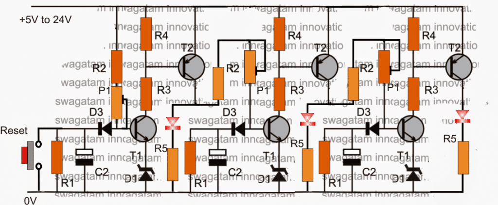
The proposed 2 LED sequential timer design can be witnessed above, it can be also used as a transistor LED sequential bar graph generator circuit.
I have shown 3 delay geneartor stages instead of two here, however any number of stages can be included as per the application specs.
Here once the circuit is powered, the LEDs are supposed to switch ON in sequence one after the other at a particular rate depending upon the values of the relevant RC components which are discretely adjustable, and may be set individually for each of the sequential stages..
Basically, the circuit is made by configuring a group of two-transistor (T1 and T2) delay ON timer stages.
Initially when power is switched ON all the LEDs or the connected loads stays switched OFF
First the extreme left C2 begins charging slowly, and after a predetermined time as set by the values of C2, R2, P1 and D1, T1 is triggered ON, with T1 ON, T2 also switches ON and the first LED from left switches ON.
With the above action T2 collector simultaneously feeds a charging voltage for the center delay timer's C2, which again repeats the cycle identically as sated above.
Due to this the center LED lights up, and its T2 feeds the signal to the right hand side stage, which goes through an identical phase illuminating the third LED in the sequence.
The situation now stays latched with all the LEDs illuminated until the "reset" switch is pressed for a few moments and released.
The pressing of the reset button enables the LeDs to shut off slowly in the reverse order sequentially.
3 Step LED Light Chaser Circuit
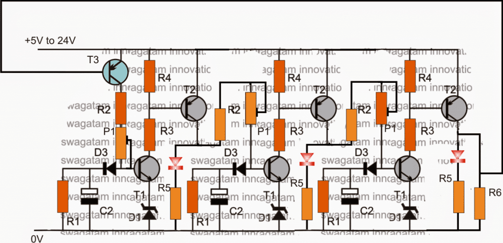
In case where the circuit is required to work automatically resembling an LED chaser circuit, wherein the LEDs are required to cycle sequentially creating an incrementing bar graph type sequence, and a reverse bar graph shutting off effect, the following shown design can be incorporated for the same.

In the above concept, T3 is initially switched ON when the circuit is first powered. Once the last LED is lit, T3 is forced to shut off due to positive potential from the collector of the extreme right hand side T2 transistor. The LEDs now begin shutting one after the other with a time lapse as determined by the value of R1s.
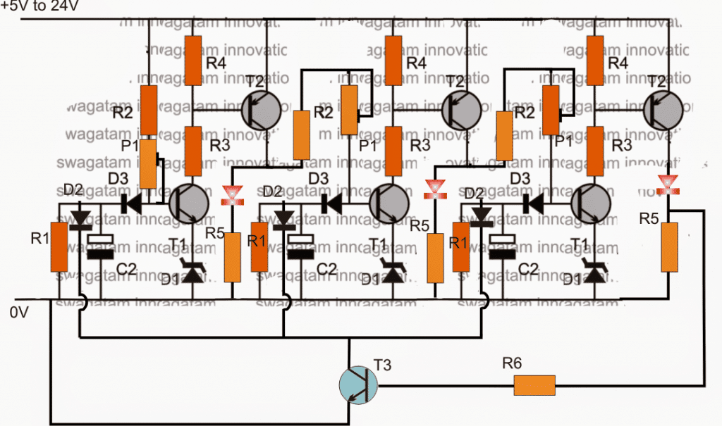
For conditions where the LEDs are required to shut off suddenly or instantly, the above design can be modified as per the following diagram:

As may be seen, in the above diagram, as soon as the last LED is lit, T3 is also triggered ON, and it forces all the timing capacitor to shut down immediately or abruptly.
When this happens all the LEDs shut off, and T3 in turn is switched OFF so that the cycle is allowed to repeat once again.
Parts List
R1 = 610K (can be adjustable)
R2 = 2k2
R3, R6 = 10K
R4, R5 = 1K
P1 = 1M pot
D1 = 3V zener diode
D2 = 1N4007
D3 = 1N4148
T1,T3 = BC547
T2 = BC557
C2 = 33uF/25V (adjustable)
