In this post I have explained a 3 powerful yet simple sine wave 12V inverter circuits using a single IC SG 3525. The first circuit is equipped with a low battery detection and cut off feature, and an automatic output voltage regulation feature.
This circuit was requested by one of the interested readers of this blog. I have explained more about the request and the circuit functioning.
You may also want to read how to design a sine wave inverter from the scratch.
Design#1: Basic Modified Sine
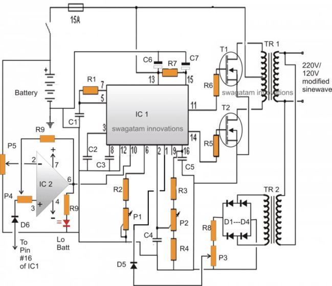
In one of the earlier posts I discussed the pin out functioning of the IC 3525, using the data, I designed the following circuit which is though quite standard in its configuration, includes a low battery shut down feature and also an automatic output regulation enhancement.
The following explanation will walk us through the various stages of the circuit, I have explained them:
As can be witnessed in the given diagram, the IC SG3525 is rigged in its standard PWM generator/oscillator mode where the frequency of oscillation is determined by C1, R2 and P1.
P1 can be adjusted for acquiring accurate frequencies as per the required specs of the application.
The range of P1 is from 100Hz to 500 kHz, here we are interested in the 100 Hz value which ultimately provides a 50Hz across the two outputs at pin#11 and Pin#14.
The above two outputs oscillate alternately in a push pull manner (totem pole), driving the connected mosfets into saturation at the fixed frequency - 50 Hz.
The mosfets in response, "push and Pull the battery voltage/current across the two winding of the transformer which in turn generates the required mains AC at the output winding of the transformer.
The peak voltage generated at the output would be anywhere around 300 Volts which must adjusted to around 220V RMS using a good quality RMS meter and by adjusting P2.
P2 actually adjusts the width of the pulses at pin#11/#14, which helps to provide the required RMS at the output.
This feature facilitates a PWM controlled modified sine waveform at the output.
Automatic Output Voltage Regulation Feature
Since the IC facilitates a PWM control pin-out this pin-out can be exploited for enabling an automatic output regulation of the system.
Pin#1 is the sensing input of the internal built in error Opamp, normally the voltage at this pin (non inv.) should not increase above the 5.1V mark by default, because the inv pin#1 is fixed at 5.1V reference internally.
As long as pin#1 is within the specified voltage limit, the PWM correction feature stays inactive, however the moment the voltage at pin#1 tends to rise above 5.1V the output pulses are subsequently narrowed down in an attempt to correct and balance the output voltage accordingly.
A small sensing transformer TR2 is used here for acquiring a sample voltage of the output, this voltage is appropriately rectified and fed to pin#1 of the IC1.
P3 is set such that the fed voltage stays well below the 5.1V limit when the output voltage RMS is around 220V. This sets up the auto regulation feature of the circuit.
Now if due to any reason the output voltage tends to rise above the set value, the PWM correction feature activates and the voltage gets reduced.
Ideally P3 should be set such that the output voltage RMS is fixed at 250V.
So if the above voltage drops below 250V, the PWM correction will try to pull it upward, and vice versa, this will help to acquire a two way regulation of the output,
A careful investigation will show that the inclusion of R3, R4, P2 are meaningless, these may be removed from the circuit. P3 may be solely used for getting the intended PWM control at the output.
Low Battery Cut-of Feature
The other handy feature of this circuit is the low battery cut off ability.
Again this introduction becomes possible due to the in built shut down feature of the IC SG3525.
Pin#10 of the IC will respond to a positive signal and will shut down the output until the signal is inhibited.
A 741 opamp here functions as the low voltage detector.
P5 should be set such that the output of 741 remains at logic low as long as the battery voltage is above the low voltage threshold, this may be 11.5V. 11V or 10.5 as preferred by the user, ideally it shouldn't be less than 11V.
Once this is set, if the battery voltage tends to go below the low voltage mark, the output of the IC instantly becomes high, activating the shut down feature of IC1, inhibiting any further loss of battery voltage.
The feedback resistor R9 and P4 makes sure the position stays latched even if the battery voltage tends to rise back to some higher levels after the shut down operation is activated.

Parts List
All resistors are 1/4 watt 1% MFR. unless otherwise stated.
- R1, R7 = 22 Ohms
- R2, R4, R8, R10 = 1K
- R3 = 4K7
- R5, R6 = 100 Ohms
- R9 = 100K
- C1 = 0.1uF/50V MKT
- C2, C3, C4, C5 = 100nF
- C6, C7 = 4.7uF/25V
- P1 = 330K preset
- P2---P5 = 10K presets
- T1, T2 = IRF540N
- D1----D6 = 1N4007
- IC1 = SG 3525
- IC2 = LM741
- TR1 = 8-0-8V.....current as per requirement
- TR2 = 0-9V/100mA Battery = 12V/25 to 100 AH
The low battery opamp stage in the above shown schematic could be modified for a better response as given in the following diagram:
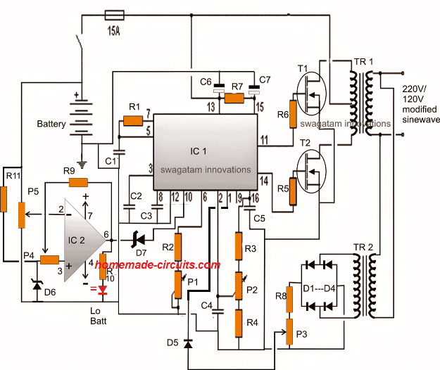
Here we can see that pin3 of the opamp now has it's own reference network using D6 and R11, and does not depend on the reference voltage from the IC 3525 pin16.
Pin6 of the opamp employs a zener diode in order to stop any leakages that might disturb pin10 of the SG3525 during its normal operations.
R11 = 10K
D6, D7 = zener diodes, 3.3V, 1/2 watt
Another Design with Automatic Output Feedback Correction
Circuit Design#2:
In the above section I have explained the basic version of IC SG3525 designed to produce a modified sine wave output when used in an inverter topology, and this basic design cannot be enhanced to produce a pure sine wave waveform in its typical format.
Although the modified squarewave or sine wave output could be OK with its RMS property and reasonably suitable for powering most electronic equipment, it can never match the quality of a pure sine wave inverter output.
Here I have explained a simple method which could be used for enhancing any standard SG3525 inverter circuit into a pure sine wave counterpart.
For the proposed enhancement the basic SG3525 inverter could be any standard SG3525 inverter design configured to produce an modified PWM output. This section is not crucial and any preferred variant could be selected (you can find plenty online with minor differences).
I have discussed a comprehensive article regarding how to convert a square wave inverter to a sine wave inverter in one of my earlier posts, here we apply the same principle for the upgrade.
How the Conversion from Squarewave to Sine wave Happens
You might be curious to know regarding what exactly happens in the process of the conversion which transforms the output into a pure sine wave suitable for all sensitive electronic loads.
It is basically done by optimizing the sharp rising and falling square wave pulses into a gently rising and falling waveform. This is executed by chopping or breaking the exiting square waves into number of uniform pieces.
In the actual sine wave, the waveform is created through an exponential rise and fall pattern where the sinusoidal wave gradually ascend and descend in the course of its cycles.
In the proposed idea, the waveform is not executed in an exponential, rather the square waves are chopped into pieces which ultimately takes the shape of a sine wave after some filtration.
The "chopping" is done by feeding a calculated PWM to the gates of the FET via a BJT buffer stage.
A typical circuit design for converting the SG3525 waveform into a pure sine wave waveform is shown below. This design is actually an universal design which may be implemented for upgrading all square wave inverters into sine wave inverters.
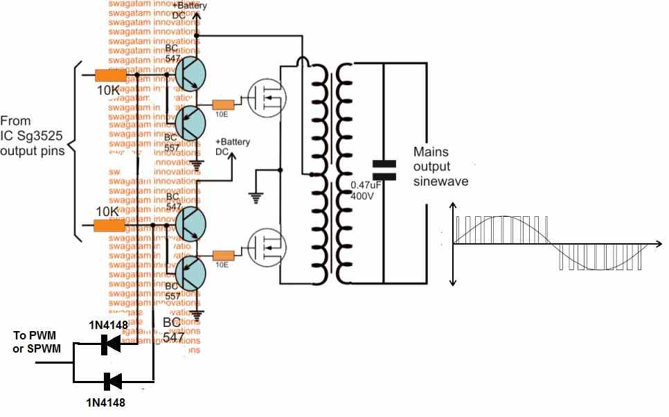
As may be in the above diagram, the lower two diodes are connected to a PWM feed or input, which causes the transistors to switch according to the PWM ON/OFF duty cycles.
This in turn rapidly chop the 50Hz pulses at the bases of the BC547/BC557 coming from the SG3525 output pins.
The above operation ultimately force the mosfets also to turn ON and OFF in the same pattern as the SPWM for each of the 50/60Hz cycles. This SPWM is then induced into the transformer primary by the MOSFETs, consequently producing a sine waveform at the output or the secondary side of the transformer.
If an ordinary PWM is used as I have explained below, then its frequency should be 4 times more than the base 50 or 60 Hz frequency. so that each 50/60Hz cycles are broken into 4 or 5 pieces and not more than this, which could otherwise give rise to unwanted harmonics and mosfet heating.
PWM Circuit
The PWM input feed for the above explained design can be acquired by using any standard IC 555 astable design as shown below:
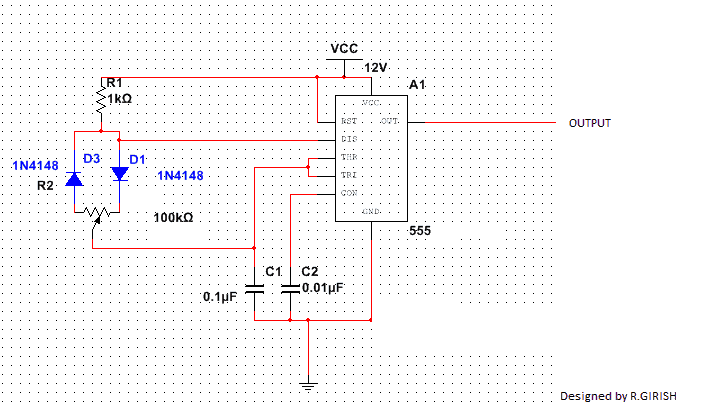
This IC 555 based PWM circuit can be used for feeding an optimized PWM to the bases of the BC547 transistors in the first design such that the output from the SG3525 inverter circuit acquires an RMS value close to mains pure sine wave waveform RMS value.
Using an SPWM
Although the above explained concept would greatly improve the square wave modified output of a typical SG3525 inverter circuit, an even better approach could be to go for an SPWM generator circuit.
In this concept the "chopping" of each of the square wave pulses is implemented through a proportionately varying PWM duty cycles rather than a fixed duty cycle.
I have already discussed how to generate SPWM using opamp, the same theory may be used for feeding the driver stage of any square wave inverter.
A simple circuit for generating SPWM can be seen below:
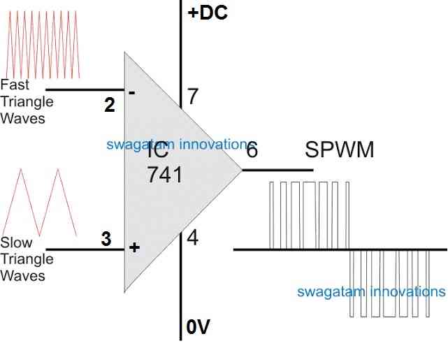
Using IC 741 for Processing SPWM
In this design we see a standard IC 741 opamp whose input pins are configured with a couple of triangle wave sources, one being much faster in frequency than the other.
The triangle waves could be manufactured from a standard IC 556 based circuit, wired as an astable and compactor, as shown below:
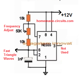

#UPDATE: The above "slow triangle waves" can be directly acquired from the Ct pin of the IC, that means you can now eliminate or ignore the above IC 555 stage for the slow triangle waves.
As can be seen in the above two images, the fast triangle waves are achieved from an ordinary IC 555 astable.
However, the slow triangle waves are acquired through an IC 555 wired like a "square wave to triangle wave generator".
The square waves or the rectangular waves are acquired from pin#4 of SG3525. This is important as it synchronizes the op amp 741 output perfectly with the 50 Hz frequency of the SG3525 circuit. This in turn creates correctly dimensioned SPWM sets across the two MOSFET channels.
When this optimized PWM is fed to the first circuit design causes the output from the transformer to produce a further improved and gentle sine waveform having properties much identical to a standard AC mains sine waveform.
However even for an SPWM, the RMS value will need to be correctly set initially in order to produce the correct voltage output at the output of the transformer.
Once implemented one can expect a real sine wave equivalent output from any SG3525 inverter design or may be from any square wave inverter model.
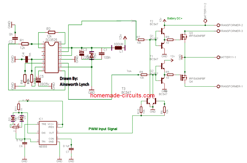
Finalized SG3525 Pure Sine Wave Inverter Circuit
The following diagram shows the finalized design of the pure sine wave inverter using IC SG3525 and SPWM, as per the above explanations.
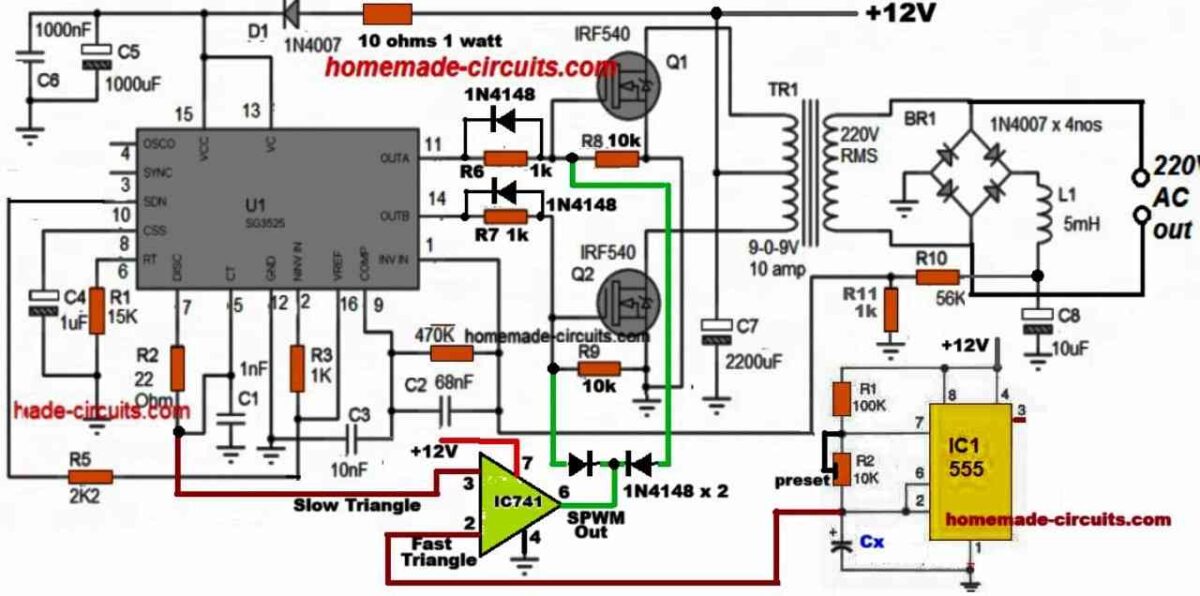
If you have any doubts regarding the above SG3525 pure sine wave inverter circuit you can feel free to express them through your comments.
UPDATE
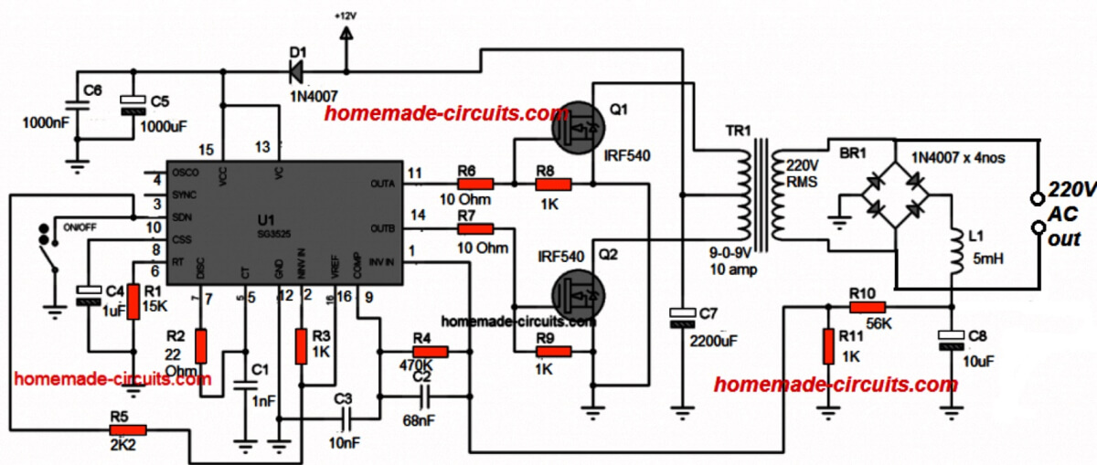
A basic example design of a SG3525 oscillator stage can be seen below, this design could be integrated with the above explained PWM sine wave BJT/mosfet stage for getting the required enhanced version of the SG3525 design:
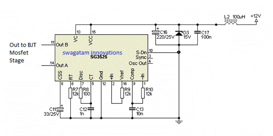
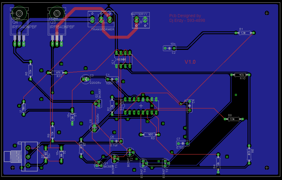
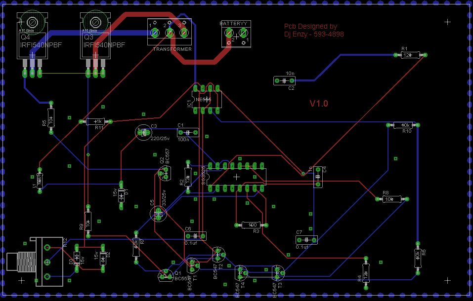
Complete circuit diagram and PCB layout for the proposed SG3525 pure sine wave inverter circuit.
Courtesy: Ainsworth Lynch
Design#3: 3kva Inverter circuit using the IC SG3525
In the previous paragraphs we have comprehensively discussed regarding how an SG3525 design could be converted into an efficient sine wave design, now let's discuss how a simple 2kva inverter circuit can be constructed using the IC SG3525, which can be easily upgraded to sine wave 10kva by increasing the battery, mosfet and the transformer specs.
The basic circuit is as per the design submitted by Mr. Anas Ahmad.
The explanation regarding the proposed SG3525 2kva inverter circuit can be understood from the following discussion:
hello swagatam, i constructed the following 3kva 24V inverter modified sine wave (i used 20 mosfet with resistor attached to each, moreover i used center tap transformer and i used SG3525 for oscillator).. now i want to convert it to pure sine wave, please how can i do that?
Basic Schematic
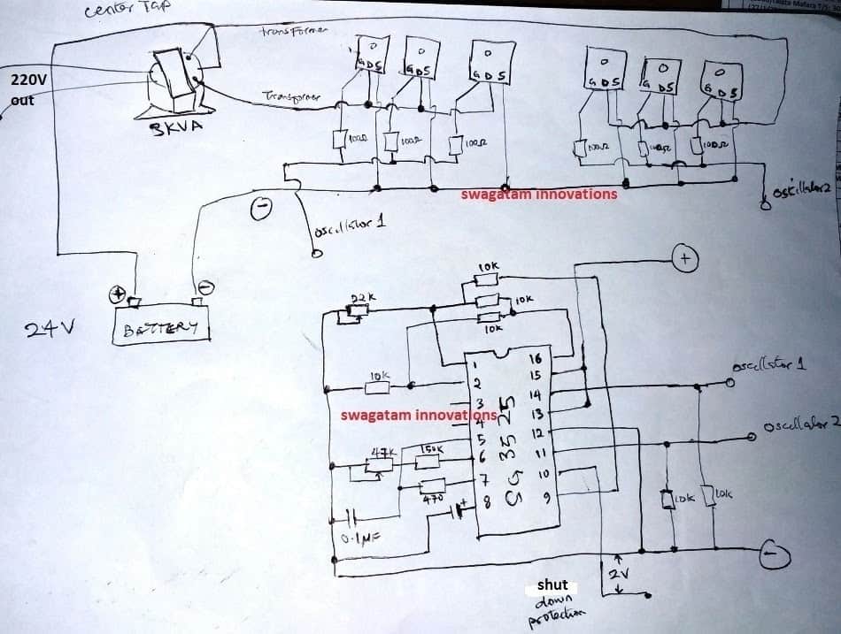
My Reply:
Hello Anas,
first try the basic set up as explained in this SG3525 inverter article, if everything goes well, after that you can try connecting more mosfets in parallel.....
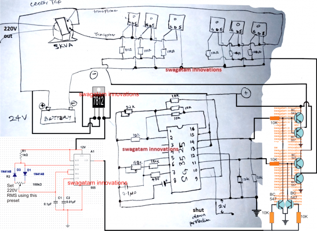
the inverter shown in the above daigram is a basic square wave design, in order to convert it to sine wave you must follow the steps I have explained below The mosfet gate/resistor ends must be configured with a BJT stage and the 555 IC PWM should be connected as indicated in the following diagram:
Regarding Connecting parallel mosfets
ok, i have 20 mosfet(10 on lead A, 10 on lead B), so i must attached 2 BJT to each mosfet, that's 40 BJT, and likewise i must connect only 2 BJT coming out from PWM in parallel to the 40 BJT? Sorry am novice just trying to pick up.
Answer:
No, each emitter junction of the respective BJT pair will hold 10 mosfets...therefore you will need only 4 BJTs in all....
Using BJTs as Buffers
1. ok if i may get you right, since you said 4 BJTs, 2 on lead A, 2 on lead B, THEN another 2 BJT from the output of PWM, right?
2. am using 24 volt battery hope no any modification to the BJT collector terminal to the battery?
3. i have to use variable resistor From oscillator to control the input voltage to the mosfet, but i don't know how i will go about the voltage that will go to the base of the BJT in this case, what will i do so that i want end up blow up the BJT?
Yes, NPN/PNP BJTs for the buffer stage, and two NPN with the PWM driver.
24V will not harm the BJT buffers, but make sure to use a 7812 for stepping it down to 12V for the SG3525 and the IC 555 stages.
You can use the IC 555 pot for adjusting the output voltage from the trafo and set it to 220V. remember your transformer must be rated lower than the battery voltage for getting optimum voltage at the output. if your battery is 24V you can use an 18-0-18V trafo.
Parts List
IC SG3525 Circuit
all resistors 1/4 watt 5% CFR unless otherwise specified
10K - 6nos
150K - 1no
470 ohm - 1no
presets 22K - 1no
preset 47K - 1no
Capacitors
0.1uF Ceramic - 1no
IC = SG3525
Mosfet/BJT Stage
All mosfets - IRF540 or any equivalent Gate resistors - 10 Ohms 1/4 watt (recommended)
All NPN BJTs are = BC547
All PNP BJTs are = BC557
Base Resistors are all 10K - 4nos
IC 555 PWM Stage
1K = 1no 100K pot - 1no
1N4148 Diode = 2nos
Capacitors 0.1uF Ceramic - 1no
10nF Ceramic - 1no
Miscellaneous IC 7812 - 1no
Battery - 12V 0r 24V 100AH Transformer as per specs.
A Simpler Alternative
can convert the out put of the inverter to charge the battery of the inverter continuously?
Yes, if your inverter has an efficiency of 110%.
Hello sir, is there any adjustments to be made to automatic voltage output feedback correction, because I want the output voltage to be 300v with the sg3525
Hi Seun,
Yes, you can adjust the P3 preset in the first two diagrams for setting up the max output voltage limit, or in the 3rd diagram you can adjust the values of the R10, R11 resistors for achieving the same…
Hi sir Well done
I tried out this circuit two times but it has an error because it does not generate pwm/oscillation.
Is pin 10 of sg3525 connected to ground or not
Hi Joseph,
Which circuit diagram are you referring to? Yes, if the shutdown feature is not required then pin#10 can be kept connected to ground.
Thanks I sorted it out but can square wave inverter run my 0.8A freezer??
Why asking this, I designed this inverter(one with feedback correction)with 8 irf3205 MOSFETS but whenever i could connect the freezer, the voltage drops to 179V AC and the compressor runs very slow. My battery is 75AH 12V but the transformer has 20AWG on the output side and 17AWG on the input side (center tapped side). Can it make an inverter of 1000W??
No problem Joseph, glad it is solved now.
No, a square wave inverter must not be used to run a freezer compressor.
To understand the freezer overloading issue, you must first verify whether your inverter is actually rated to handle the 0.8 amp current or not.
For this you can connect a 200 watt or a 250 watt incandescent bulb at the output of the inverter and check whether the voltage drops or not.
If it does then your transformer is not rated to handle tis much current or maybe it is not correctly rated as per the PWM adjustment of the sg3525 circuit, or maybe the PWM itself is not adjusted correctly.
Thanks so much, I tested it with a 200w LED flood light and the voltage drops.Am using the E&I transformer should I replace it with a torroidal one???
With the PWM rating, I tried to adjust in all ways but it had the same issue.
The core does not matter. Even an EI core should be able to provide the desired results if the winding is implemented correctly.
If you are having a toroidal replacement, you can try it and check the response.
ok sir I’ll update you
Ok, no problem…
Please sir, is it possible to build an 800v voltage inverter input with sg3525 Ic
Bay, yes it is possible, you just have to use a 800V transformer/battery and make sure to supply 12V DC for operating the SG3525 IC.
I mean for 3phase inverter system
Sorry, this IC cannot be used for making a 3 phase inverter.
In fact or description is excellent, but I need Advice. how To start ??
I need to build 3000W pure sine wave inverter with feed back and low battery protection
With SG2425 and mofettes ( Should run on 12V Battery )
is it better to use Arduino or normal pwm IC’s like SG2524
Sure, you can start by building and testing the following basic design. However a 12V can be highly inefficient and bulky for making a 3kv inverter, instead you must go for a 48V battery.
" rel="ugc">
normal ICs are easier to configure
Sir I’ve finish building this project (the hand drawn one) but only get 22v athe output. What might be wrong?
Hello Andrews, It will be difficult for me to troubleshoot your circuit without checking it practically, so i would recommend to build and test it in a step wise manner. Please start with a basic SG3525 inverter using single MOSFETs as shown below:
" rel="ugc">
If this works then we can proceed with the further upgradation.
Thank you very much. I’ve changed the transformer to 9v-0-9v to 230v transformer and now the output voltage is 230.
OK, good! Glad it is working now…
Merry Christmas sir, I am about to build a full h bridge low frequency sine wave inverter with SG3524 and lm324,
I have successfully built the two triangular generators separately using 2 lm324, the slow triangle is 50hz and the fast triangle is 450hz, these two triangular frequencies have been connected to lm358 to give me spwm signal.
The 2 outpts from the sg3524 are 50hz square wave giving a total output of 3 signals.Full h bridge circuit require 4 signals to trigger, my question is should I split the output of the lm 358 to two inorder to get the fourth signal?
Merry Christmas Richard!
I cannot figure out how you have configured the 3 phase from the IC SG3524.
Can you upload the schematic to this comment? Only then I would be able to provide a proper suggestion.
Also, for the slow triangle waves, you do not need a separate circuit, you can simply get it across the timing capacitor of the SG3524 IC.
I tried the pin ct on sg3524 for the slow triangle the voltage of the triangle was low that’s why I constructed another slow triangle using lm324 that gave the same width as the fast triangle
Please check the peak voltage of the Ct pin triangle waves using an oscilloscope, that will give you the exact peak value of this pinout. The triangle waves from the Ct pin is necessary for proper synchronization with the inverter frequency of 50 Hz.
Hello Sir Good day please I want to ask can I use the pwm or spwm circuit above to convert a square wave from ic sg3524 to a pure sine wave or do I need additional circuit
Good day Samuel,
The above SPWM concept can be used with any inverter oscillator IC to convert square waves to sine waves, so you can use it for SG3524 also…
Hello Sir. is it possible to run LEDs using the SG3525 outputs?
Hi Jedidiah, yes, it is possible, how exactly do you want to run the LEDs? But using this IC for lighting LEDs would be an overkill..
Alright Sir. I was thinking of a pulse generator that responds to a ceramic piezo sensor hence produce flashes. Its actually a door knock sensor that should respond visually to a vibration with flashes of light.
Thank you Jedidiah,
a door knock sensor that should respond visually to a vibration with flashes of light….for this we can simply use the IC 555 monostable circuit, the SG3525 is not required according to me.
How many MOSFETs do I need to add for 3000 watts? What should the transformer feature be?
You can use a 48V battery for the transformer and the MOSFET stages.
Parallel MOSFETs are not required, you can used single IRFP2907 MOSFETs.
Battery can be 48V 600 Ah lead acid battery.
Transformer can be 40-0-40V, 70 amps
Thank you Sir, from the hand drawn circuit I can see you’ve written “shutdown protection” between pin 10 and -VE, indicated 2v. Please am little bit confuse there, can you explain it to me?
Hi Andrews,
That is the shut-down input pin of the IC. If you configure a feedback system with this pinout, then if the feedback voltage increases above 2V, will cause the IC output to shut down or narrow the PWMs.
So can I leave the pin#10 of the SG3525 not connected?
No, it must be either configured with a feedback network or kept grounded.
please can I get the gerber file?
I don’t have the gerber files for this project unfortunately…
please I need your guide sir, I made 24v inverter using irfp 260 MOSFET(1pc) when I put on My CRT TV at night the MOSFET doesn’t blow, but another 60v inverter using psm50s20 MOSFET(1pc) it blows at night but not during the sunny day with solar.
although the TV has high starting surge
Hi Daniel, I could not find the datasheet of the psm50s20 MOSFET, so I cannot figure out why it is blowing up. However it is better to use standard MOSFETs like IRF540, IRFZ44 etc instead of any other untested variants.
Thanks sir, sorted out. Another issue is that on heavy load like freezer, it is not stable, please what can I do?
That’s good Daniel,
If the load is not stable then you must upgrade the transformer, MOSFETs and the battery according to the load. The output power must be much higher than the initial surge current intake of the freezer.
Sir, I want to build the Finalized SG3525 Pure Sine Wave Inverter Circuit. what are the voltage for the various capacitors?
Hello Kumah, all the capacitors can be rated at 25V.
Hi Swagatam,
Am a big fan of yours. Am a hobbyist ,electronics technician and electrician.
I first built your 3stage high current charger to perfection ,some 7years ago and an inverter using Sg3524 ic
.The circuit is from this site
" rel="ugc">
.
it worked well for years till recently,it got damaged,I replaced MOSFETs with f1010e,but maintained the buffer transistors.
here is my challenge:
-sg3524 output reads 3v,
-mosfet overheat and blow above 150w ,
Am using 2 MOSFETs per channel.
I have a 7809 for the ic.
f1010e should work well,why the blowing, this inverter works,something is off.
I want to get running then use your 555 ideah to convert to pure sine wave.
it’s a 12v inverter,transformer is 1200va,900watts ,10-0-10 center tapped.
help please!
Thank you Ronnie,
If you are using 9V supply for the IC, then the peak voltage at the output pins of the IC should also around 9V.
So, you must confirm whether this is happening or not, and you will also need to check the frequency across the output pins, which must be 50Hz or 60Hz.
Without a minimum of 9V at their gates, the MOSFETs will not operate correctly and might keep blowing.
Do you have an oscilloscope, if yes then you can use it to confirm the above details across the IC output pins….
Hola ing. voy a proceder a armar este inversor se onda senoidal, seria necesario poner un regulador 7812 ?
You can add the 7812 IC after the diode D1 in the following diagram: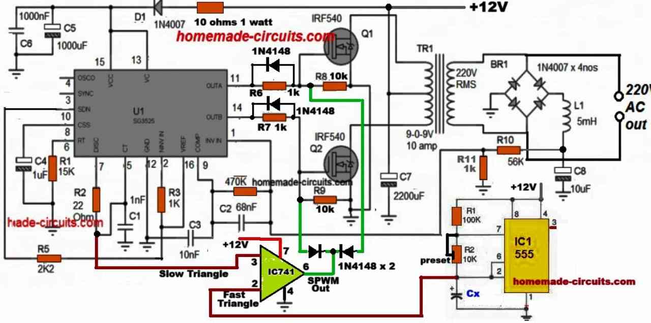
" rel="ugc">
How could the design be if I want to increase 2 mosfets?
You can put any number of MOSFETs in parallel in the existing design without any changes in the circuit.
Thank you, another query would be necessary to add two more diodes 1n4148 at the exit of pin 6 in ic741 if I am going to add god mosphets more or just connect it to the diode 1n4148 x2 that are in the design?
If you want to add more number of parallel MOSFETs, just connect their gates, drains, and source terminals with each other, in common, in the existing setup, that’s all, no need to change anything else in the circuit design.
Hello all right ? about the sine inverter I found cool one thing I did not understand was the fact that the gate resistor is de1k something else and about the output stabilization part is not isolated I found it dangerous what I will suggest and use an optical coupler pc 817 with a TL431 to make the output control making more efficient and accurate.
Yes, the gate resistors are 1k, the high value is required for reducing loading of the op-amp.
The MOSFET gate discharge will not get affected by the high value 1k because of the reverse 1N4148 diodes.
Sure, you can make the feedback isolated using an opto-coupler.
Good day Engineer Swagatam, please what can I do to My efficient modified sine inverter, it could not power a brand of laptop charger, whereas the grid powers it, other brand laptop chargers are working with the inverter.
Hi Seun,
That specific brand could have been designed to work with pure sine wave AC only, that is why it might not be accepting a modified sine wave AC.
Thanks engineer, your guide article was amazing, I got a cleaner wave, but this pure sine wave consumes much more current than modified wave inverter, why is this so, sir.
Thanks Seun,
PWM sine wave should consume less current because it uses PWM technology, if it is consuming more current, then you must investigate why this is happening…
SIR, WHAT TO DO FOR PROTECTION OF IC3525 IN PARTICULAR CIRCUIT
Anil, you can supply 12V DC to the IC through a 7812 IC, and also the arrangement of C6, C7, R7, as shown in the first design.
Hi sir
I want to control duty cycle of dsp30f2010 plz help me also I have sent an email about project
Hi Azhar, sorry, i have not yet investigated this specific IC, so currently i have no idea regarding its working specifications…possibly I will try to study it and try to figure out your problem.
is there any other way to filter a square wave to sine wave using RC filter
Here’s an example of a sine wave inverter using RC filter: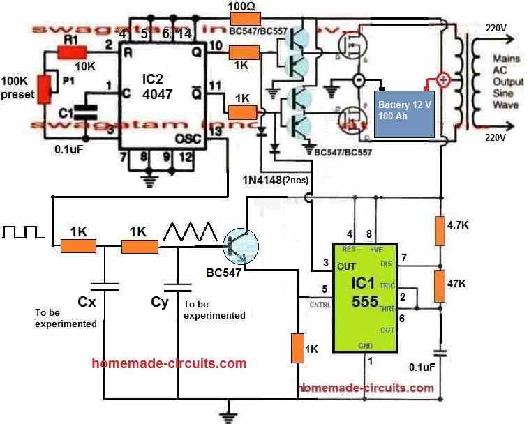
" rel="ugc">
Thanks for this, please what kind of capacitors are CX, cy, and please give a values to experiment with.
In the finalized sine wave design, CX must be adjusted to a value which generates triangles waves of around 300 Hz, you can try any online 555 calculator to find the value of this CX….where is CY, i cannot find it?
please what type of capacitors are they electrolytic or ceramic
It cannot be electrolytic because the value could be in nF or pF. So, you can use ceramic disc or PPC…
please sir, help out, will CX, cy be same values, please I can’t find any online calculator to calculate to get 300hz, the ones online are only astable.
Here’s the calculator you can use to find CX:
ohmslawcalculator.com/555-astable-calculator
I cannot find where is CY??
You’ve asked in Oct 14, 2024 about 2 experimental items (CX & CY) you drew on a picture " rel="ugc">
I was referring to this diagram:
" rel="ugc">
Thanks, I checked it out.
However, I read you asked for the same item twice (above) when a person asked [Seun October 14, 2024 please sir, help out, will CX, CY be same values, (…) ], but that man never answered, and I felt compelled to fill in that blank, since you currently NEVER left and open question like that (unless a lazy person wanted you to do all the jobs).
I will visit that site often. That’s an electronic library, sir! I hope it never pass away (like me).
Thanks AJTH, for your kind words. I appreciate it very much…
If you are referring to the 4047 circuit, it is actually an RC series integrator circuit.
The best way to get the values of CX and CY is to find it through some trial and error and practical experimentation, because calculating it can be a lot difficult.
Hello sir, please can I use sg 3525 inverter circuit to invert 48v DC to 12v ac
Hi Daniel, yes, you can convert any voltage to any level as you like, using an inverter IC like SG3525 or any other similar IC. It simply depends on the transformer winding ratings…
please how can I embed WiFi network to monitor and automate sg3525 inverter design.
Daniel, Currently I do not have any circuit for monitoring an SG3525 inverter through Wifi network…
I discovered with 12v AC output, the transformer saturates causing damage. Please how will I do it?
Please explain your problem in detail, I cannot understand it.
I will to design an inverter with DC input 48v that will output 24v Ac, I am thinking if I make turns for primary and secondary windings with these it might saturate please guide.
Sure, for designing the transformer you can refer to the following article:
https://www.homemade-circuits.com/how-to-design-your-own-inverter/
I tried making a 20Khz inverter boost board I bought on Aliexpress to have adjustable output frequency range of 100Hz to 100Khz. It came with Ct=10nf, Rt=3.3kohm and Rd=100ohms. I replaced Rt with a variable pot of 100Kohm. The booster board stopped working consistently, sometimes draws high current from my source once I turn it on. And when it does not draw high current, there is no output. I have tried this for three boards, the same result. Please what can I do? Can I order a board for you to help me work on?
Please provide the IC number of the module, or provide the schematic diagram, only then I can help to solve the problem…
Thanks so much for your prompt reply!!
The IC number is SG3525AN (HLF 22A8).
Kind Regards
Hello ThankGod Amaechina, Changing the frequency is not recommended for any boost converter circuit, because the parts and the inductor values of all converters are calculated using a fixed frequency. Instead you must change the feedback to adjust the output voltage.
You can try the following designs to build your own boost converter using SG3525 IC.
https://www.homemade-circuits.com/dc-to-dc-converter-circuits-using-sg3524-buck-boost-designs/
I noticed that pure sine wave strained MOSFETs than modified sine wave, is this correct, sir?
MOSFETs are built to handle high frequencies in the MHz range, so an SPWM with a few 100 Hz frequency can have no adverse impact on the MOSFETs, according to me…
please I found out that the 18k resistor for the fast wave is getting very hot, I don’t know what went wrong/
There’s no way the 18k resistor should become hot? Even if you connect the 18k directly across the 12V DC supply still it cannot become hot?….how much DC supply are you using for powering the 555 and the SG3525 circuit?
I will try to update the complete schematic of the SG3525 sine wave inverter soon…
please before upgrading to spwm, the output frequency was 50Hz , but after it became 150hz, please assist
Please add a 3uF/400V PPC capacitor across the AC output of the transformer and check the frequency again, it should be 50Hz.
Hello sir, I noticed when I connect the spwm complete circuit, it works but after 10-15secs, it stops working. I restart again, same thing.
I now found out that the step down voltage regulator IC for 12v supply is getting hot when the spwm circuit was connected. but when I remove it, the regulator is not hot.
please kindly assist.
Hello Daniel, which schematic are you using exactly?
Good morning Sir
Thanks for the great work you are doing.
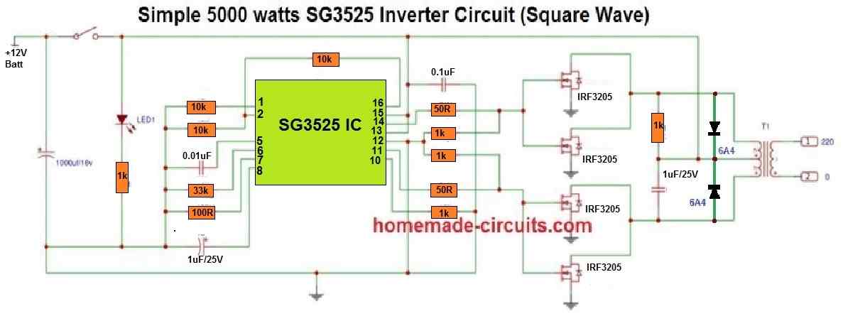
Sir I am interested in the last circuit. The 5000Watts square wave. And have two concerns
1) Can just those 4 MOSFETs 3205 be able to support 5000Watts?
2) please for the Circuit of a pure sine wave version of the 5000Watts Inverter.
thanks
Hello Ngang,
Sorry for the confusion, actually single 3205 MOSFETs cannot handle 5000 watts, especially when the voltage is 12v.
You would require at least 5 MOSFETs in parallel on each of the channels.
I would actually recommend IRFP2907 MOSFETs instead, which are even more powerful than 3205.
Okay Sir. Thanks very much for the clarification.
Sir, I need a 5000Watts pure sine wave inverter circuit diagram
Thank you NGANG, I think you can first complete the square wave 5000 watt inverter circuit and confirm the results then we can convert it to a sine wave inverter.
Sir, I made an inverter with 2 stages, my circuit was normal but for some reason an explosion occurred. now I’m fixing this circuit. stage 1 with sg3525 and stage 2 with egs002. My stage 2 is probably normal but for stage 1 it doesn’t seem like it. I did a load test after the transformer (before the stage 2 circuit) there was a drop in the power supply voltage/source voltage from 12v to 8v. I wonder, is my IC 3525 the problem or my HFT? inverter spec 1000watt 12v to 220 pure sine wave EE55 transformer
Hi Kwk,
I am not sure how a SG3525 can be used with EGS002? It is simply not required, because EGS002 by itself is a full-fledged inverter module and does not require any external oscillator IC? Let me know your opinion on this.
pls send me a full diagram of pure sine wave inverter with part label using sg352 4 or 4047ic
You can go through the following article, this may help you to learn the details:
https://www.homemade-circuits.com/designing-a-sine-wave-inverter-circuit-from-the-scratch-tutorial/
Hello sir, please I want to build an inverter with 60v input, please how I keep the battery well managed, not to have imbalance state. Thanks Engineer Swagatam
Hello Grace, If you are using many batteries in series, then you will need a balance charger circuit to keep proper balance across the batteries.
I have a balancer circuit, but it is not tested by me yet:
https://www.homemade-circuits.com/lipo-battery-balance-charger-circuit/
Hello Swagatam, I constructed the Basic modified sinewave inverter in design number one. But when i power the circuit the wires connected to the MOSFETS is burning out, I presume is because the current carrying capacity of the jumper wires are not good enough. So, I am changing the wires now to thicker once. My question is, without loading the circuit is the current flowing through the mosfet supposed to be that high to burn off the wires?
Hello Collins,
If your MOSFETs are burning that means there’s some serious fault in your circuit.
In that case please remove the MOSFETs and first confirm whether your IC outputs are generating the required frequency or not?
If you IC does not oscillate and produce the intended frequencies at the MOSFET gates then your MOSFETs and the transformer both might burn.
So, please disconnect the MOSFETs and confirm if the IC is oscillating or not.
Hello Swagatam,
Thank you for your response. I will do that and keep you posted.
No problem Collins, all the best to you.
Hello sir, will the Spwm generator link to in4148 or BC 547 for the bjt buffer stage, please which one is better?
Hello Daniel,
1N4148 is the better option, so please use iN4148 diodes for feeding the SPWM to the buffer BJT bases.
Thanks sir, please the direction of the diode will block current
Daniel, the diode direction is correct, it is supposed to be reverse biased…it is positioned to conduct during the off pulses from the the op amp output…
Is it in order in the article
Yes…
Hello Mr Swagatam, thank you for your informative lessons on electronics, it has been beneficial.
How can I synchronise Sg3525 IC to make 3-phase inverter?
Hello Seun,
I don’t think SG3525 ICs can be used to generate sequential 120 degree phase signals for operating MOSFETs in 3 phase configuration.
please sir, I need sg3524 inverter circuit with well controlled pin 9 to give constant output 220v AC irrespective the battery voltage. thanks
Daniel, the feedback can produce a constant voltage only as long as the battery voltage is above normal. If it drops below normal then the feedback cannot help.
Thanks, I agree with this, a colleague argues it remains constant, irrespective of the voltage
If the battery is low or if there’s an overload, the feedback cannot raise the voltage, the output voltage will drop. Please ask your colleague how to do it.
please how can I put a soft start to the inverter circuit
Capacitor at pin#8 of the SG3525 IC decides the soft start.
Thanks for your reply, I am working with Sg3524 IC, how will I add soft start, and value. Thanks.
For SG3524 IC soft start, connect a 1N4148 diode at pin#9, anode to pin#9, then connect its cathode to the positive of a 4.7uF capacitor, negative of the capacitor to ground.
Thanks Swagatam,I appreciate you. I already has 4.7uf and 1k resistor connected in series into pin 9 and ground. How should I add the diode then, sir?
Daniel, then i think you must replace the 1k with the diode, and check the response.
Thanks sir, how will I test it’s response.
2. if I want to incorporate your guide for Ana’s 3kva inverter using 555 timer only, will I adjust anything.
With the slow-start added, the output voltage will not rise quickly to 220V, rather after a second or two.
If you want to add soft-start to Ana’s circuit, you can do it by adding a capacitor between pin#8 and ground, no other changes would be required.
Sorry sir, I meant to make it pure sine wave for Anas circuit, is there anything, I will modify in the 555 timer. Thanks Swagatam.
For making a pure sine wave inverter, you will have to employ the opamp technique, using fast and slow triangle waves.
Hello sir, My breaker used to trip off when the MOSFET blows, but because My batteries a weaker, it doesn’t anymore, putting more stress on the battery.
Please can I get a trip off signal from the sg35xx IC to off the relay if I use relay instead of breaker. Thanks Swagatam.
Daniel, getting a trip off signal to turn OFF a relay may not possible, or may be complicated, however you can initiate an instant shut down of the inverter and prevent the MOSFFETs from blowing, by appropriately configuring the shut down feature of the IC.
hi swagatam
it seems 555 doesn’t provide perfect triangle instead provide sawtooth , is it not a problem?
second thing voltage level from ct pin of sg352x is lower than that from 555 pin2 (fast tringle ) lead opamp to not trigger
, using lm358 in place of ua741 is correct?
Hi Abu,
Yes, the triangle waves are not perfect but still we can get a reasonably good sine wave output. The sine output will be much better than a modified output. Actually the slow triangle wave must be a sine wave ideally.
What are the peak values of the two triangle waves, did you measure them, please specify if possible??
LM358 can be used, or a comparator IC can be also used with appropriate modifications.
peak voltage of slow triangle is about 5v and that of fast is about 11v
Even with this difference in peak voltage, spwm will be generated at the output of the opamp, because fast triangle waves would be comfortably intersecting the slow triangle waves.
Sir, from this comment, can I still 741 IC for processing the spwm, because Abu reported that there was no trigger from the slow and fast wave
Daniel, IC 741 can be used, please see my reply to Abu.
Thanks sir, you advised We use a Trafo 9-0-9 v, @ 9v the MOSFET blew but worked well without blowing @10v, can I still use the Trafo for the PSW
Daniel, At 9V the MOSFET should never blow, there could be some other hidden issues, for example mosfet not rated as per trafo current.
Hello sir, please why is the amperage readings from the clamp meter is confusing. When I plug the electric stove it reads 2.35amps and battery drains fast. But with other loads without the stove it reads 4.25amps but the battery last longer.
Hello Seun, I think your meter is malfunctioning, because it’s showing the wrong results.
Thanks for the reply. Please how can I make My inverter efficient so that the standby current consumption will be 0.95A like factory made inverter rather than 2.24Amps.
You can add an ON/OFF switch in series with the positive line which connects with the transformer. If the supply to the transformer or MOSFETs is switched OFF the standby current will reduce drastically.
Thanks for this advice, won’t the inverter be totally shut off, also, will the switch handle the current when it is on load, please kindly advise what to do to make it seamless
Only the load and the transformer would be switched OFF, the IC and the MOSFETs would remain operational and in a standby mode. You must use a switch that is appropriately rated, to handle the load cuurrent.
I put a circuit breaker as the switch but shut off the inverter. What is the difference between a switch and the breaker
There’s no difference unless your circuit breaker has an automatic turn OFF system.
I don’t understand automatic off, because it doesn’t trip off by itself. I put it off by myself.
In that case it is same as the switch, no difference.
To reduce the standby current from your inverter like that of the redimade ones, you need an inductor in series with the positive lead from the battery to the transformer centre tap (that is for push-pull configuration). Or you connect an inductor in series with one terminal of the transformer before it reaches the H-bridge MOSFET’s connection (that is for H-bridge configuration/ non center tap transformer).
The inductor must be wound on a ferrite ring core and big enough to handle the current require from the inverter also it should be 8turns to 12turns. Then the thickness of the wire must be specified with the current needed in the inverter.
Dear Mr. Swagatam,
If an inverter with 100 KW power output at 50 kHZ is to be built what core would you be using? Can you please specify a core?
Thanks and kind regards,
Job Thykkoottathil.
Hi Job,
For 50kHz only a ferrite core is suitable, so you can use a ferrite core transformer.
Dear Mr. Swagatam,
I was thinking of a ferrite core with permeability 1300G. But not sure what the effective area and other dimensions should be. Just wondered whether you could help.
Kind regards,
Job.
Dear Job,
I think you will have to calculate the parameters accurately. I have posted an article on this, you can refer to this for more info.
https://www.homemade-circuits.com/how-to-design-and-calculate-ferrite-core-transformers-for-inverters/
THANK YOU SO MUCH MR SWAGATAM FOR THE QUICK RESPONSE, I REALLY APPRECIATE.
You are welcome Godspower!
SIR, PLEASE CONVERTION TO SINE WAVE IN THE ABOVE CIRCUIT, WILL IT ALSO WORK FOR SG3524. THAT WHAT AM HAVING IN MY LOCATION NOW.
Yes, it will work for SG3524 also.
GOOD DAY MR SWAGATAM, PLEASE MY QUESTION IS TAKEN FROM THE CIRCUIT DIAGRAM OF MR ANAS, WHERE YOU REPLIED TO HIS CIRCUIT MY ADDING PWM AND THE BJT TO CHOP THE SIGNAL FROM PIN 11 AND 14.
Hi Godspower,
If the voltage to the ICs are regulated using a 7812 ic, or a 7809 ic then the pwm will be stable, and the output voltage will also be stable and there won’t be any need of using a feed back.
The 741 ic circuit is universal.
Hi. I am reading this article very closely and I am confused with circuit design #1 wherein a small sensing transformer TR2 is used. The article states that the rectified output of TR2 is fed to Pin 2 (non-inverting input) of the SG3525S IC. However, looking at the circuit schematic, it seems that this rectified output is actually fed to Pin 1 (inverting input). Can you please clarify. Thank you very much.
Hi,
Sorry for the confusion. Yes, the feedback from the sensing transformer goes to Pin#1 and not Pin#2. Pin#2 is the reference pinout clamped with 5.1V reference value. I have corrected the typo accordingly now.
Hi, Mr. Swagatam, I had been following you r articles here in the Philippines. If I may, can you send me a complete detailed drawing for the PSW circuit you designed and inserted/incorporated to the basic 5kva 24vdc 220v output inverter by Mr. ANAS HAMAS.. Can you help me to have a PCB layout of that 5kva PSW inverter circuit? I am not a professional tech but only a newbie but can follow instructions.
Thank you for this opportunity to connect with you.
Egay Diolola
Thank you Edgardo, glad to meet you.
I understand you want to build the 5kva PSW inverter, however designing the PCB can be extremely time consuming so it won’t be possible for me to provide the PCB design.
That said, you should not build the whole 5kva circuit at once, you must first build a basic 100 watt version, then integrate the sine PWM and check the results, if everything works correctly, only then you must upgrade the MOSFFETs and the transformer for building the 5kva version.
Also, this design is very complex and will require testing and confirming the stages through an oscilloscope, therefore it may not be recommended for any newcomer, please proceed with caution.
Pls if we can get a pure sine wave using the ic sg3525 used above, i will also be happy because i undertand the schematics above more. I’m new to this, please be simple in explanations, i will appreciate that so much sir. thanks, waiting for yor reply.
Hi, In the above article I have explained elaborately regarding how to implement the pure sine wave feature in a SG3525 inverter circuit. You will read it carefully to understand all the steps.
Thank you very much, I appreciate this response and how fast it came through.
Hello,
First, I want to say thanks for your sharing of this knowledge of yours in this simple way, though not all that simple for me. my question is that I’m working on a pure sine wave inverter and I’m working with a cd4047, can you help me witth a more suitable schematics or guide on that, i have been seeing people working with CD4047 but they always have theri oscillator pin 13 left out, they don’t seem to have the explanations on why they did that, leaving the pin empty. I’m expecting your reply sir, thanks again.
For a 4047 pure sine wave inverter you can refer to the following post:
https://www.homemade-circuits.com/pure-sine-wave-inverter-circuit-using/
Regarding the output pinouts suppose your 4047 IC is set to produce 50 Hz frequency, then the pin#10 and pin#11 will alternately generate 50 Hz frequency while the pin#13 will generate a 100 Hz frequency.
Ok, thanks.
Bonjour chers techniciens merci pour cette matière
You are welcome Richard!
Is it necessary to include the error voltage circuit powered by 0-12volts transformer through the 2.2K pot as part in the Pure Sinewave Inverter Circuit, OR it’s unnecessary?
I am unable to find any circuit with 2.2K pot, please given more details about which circuit design you are referring to?
Hello. About the Pure Sinewave Inverter Circuit, should I use two 15v zener diodes or two 1N 4148 in the PWM circuit?
Secondly, what should I incorporate/consider as most important circuit, Short circuit/overload current protection OR Low battery & overload protection?
Hello, You will have to use 1N4148 diodes as shown in the diagram.
All those can be considered important. For the protections you may incorporate suitable feedback networks, as explained in the following article:
https://www.homemade-circuits.com/inverter-circuit-with-feedback-control/
I need circuit idea for High frequency plastic welding (dielectric heating)
old circuit all are using vacuum tubes such like 833a. 7t85 rb.7t69rb
but I need igbt based circuit
out put capacity is 5kw frequency 27mhz
Sorry, I do not have this circuit with me right now.
Can use sg3524 circuit to replace the sg3525 circuit
Yes you can do it.
Can I use this circuit to power twenty mosfets
Sure, you can put as many MOSFETs as you want.
Hello Sir Swagatam!
Hello Laszlo!
Thank You! Commenten My Easun Inverter pure sine 3000 w distroed modul ,diy replacement
Sorry, an exact DIY replacement module may not be possible for your specific inverter, you will have to contact the manufacturer for the module board.
Hello, sir,
Is there an error in the last diagram “A simpler alternative”? the resistor connected to the seventh leg goes to minus, but should go from the 7th leg to the resistor and to the 5th leg of the microcircuit;
Thank you
Hello Danil, You are absolutely correct, thank you! I have added the correction message just under the image.
Hello sir,
Can I use BD139/BD140 in place of BC547/BC557.
Thanks
Hello Olusegun,
Yes, you can use them, but that will be unnecessarily costlier and bulkier.
Thanks for your quick response all the time. I have them at my disposal. That’s why I’m asking.
No problem! You can use them.
Sir, can I get a pure sine wave non transformer based inverter circuit diagram
Hi George, you can refer to the following article:
https://www.homemade-circuits.com/5kva-transformerless-inverter-circuit/
What is the difference between 4MOSFET and 6 MOSFET amps or volt gain please replay ,can I change 4 MOSFET board instead of 6 MOSFET board in bus mini inverter
If you increase the number of MOSFETs in parallel it will increase the power handling capacity of your inverter and vice versa. How many MOSFETs to be used in parallel will depend on the max power requirement of the load.
Dear Swagatam
I first wanted to build the 50hz modified sine wave inverter before converting it to pure sine with the sg3525 I, my problem now is that all 6 pcs of the sg 3525 ic are fake so I have no alternative other than to use the tl494, I have successfully built one as described in your blog but I am getting a frequency of 400hz and above, any help please for 50 hz
Hi Richard,
Unfortunately the frequency of a TL494 IC cannot be reduced to 50 Hz, so we cannot do anything about it. You can instead try a 4017 IC based modified inverter circuit with perfection and with a 50 Hz frequency.
I have made this project and it works well but I have made some changes to it which enable me to get the true pure sine wave at the output .
The changes are:
1: for my external fast PWM generator that I use to breakdown the slow PWM from SG3525 circuit I used 50% duty circles mark 555time circuit.
2: I set the frequency of the fast PWM generator to 16khz which enables the multiple breakdowns of the 50hz that is generating from the SG3525 circuit.
With this configuration it gives me a true pure sine wave at the output after applying 1uf/450v capacitor.
The value of the capacitor is chosen in respect to the capacity of the inverter, my inverter capacity is 1kva which is 850w so one can select the value of the capacitor due to it inverter capacity for 1.5kva one can use 1.2uf/450 to 1.5uf/450v, for 3.7kva is 2.5uf/450v, for 500va is 0.22uf/400v to 0.47uf/400v, for 5kva is 4.75uf/450v, and etc.
Thank you so much Emmanuel, for your valuable suggestions. Glad you could build the sine wave version successfully.
I appreciate it very much. I hope the readers will find it very useful.
You are welcome swagatam and I also appreciate your love in sharing your knowledge to people who are willing to learn.
Another thing I will say is that please you should always verify any circuit you upload and see their performance before uploading, the reason I’m saying this is that there is no workable 50Hz inverter circuit in this article here and I have gone through comments and I have seen people complaining about heating of MOSFET and different types of malfunction of their circuit, the reason is because non of the circuit that I have seen here is 50Hz because they are high frequency circuits (50khz) not low frequency circuit(50hz). If you want them to work at 50hz then the capacitor at Ct pin of the SG3525 should be 0.1uf not 1nf, and the resistance at Rt pin of the SG3525 should be 142400 ohms (142k4) not 15000 ohms (15k) and resistance at Rd pin should be 100 ohms (100R), with this configuration one can achieve 50hz at the output of the transformer and another thing is oscillating output pin of the SG3525 which is pin4 should not be tempered with because it will distorted the output pulse of pin14 and pin11 of SG3525.
With all of the explanations I think everyone should be able to set up his system and I will surges anyone trying to design this project should first try and design the PWM version and see whether is working fine before going for this SPWM version.
Thanks for having me.
Hi Emmanuel, I appreciate your suggestion, however it is not possible to check and test each and every circuit before uploading. Moreover these types of circuits are meant for people who are well versed with electronics and basically know how to fix small issues in a circuit, just as you did. The design of the concept is the crucial thing which must be perfectly examined before posting, and I always do that.
Anyway, thanks again for your valuable inputs, I am sure other visitors will benefit a lot from them.
You are welcome sir
thanks for accepting my opinion.
please sir, can you simplify how he got 50% duty cycle with 555 timer.. thanks Swagatam
Daniel, the 50% duty cycle can be adjusted by correctly calculating the timing components of the 555 astable circuit, although it can never be a perfect 50%
please sir, do you recommend I configure the fast generator wave from 555 circuit above to 16khz as it was done by Emmanuel and pick slow wave directly from CT pin 7 of sg3524ic, or I do the 555 timer circuit for slow wave. thanks
Daniel,
You can pick the slow triangle waves from Ct pin of the IC, that’s crucial. And the fast triangle waves can be from any suitable source.
The fast triangle wave frequency can be any value, right from 400 Hz to 100 kHz, however if it is higher than 500 Hz then the transformer will need to be a ferrite core transformer.
can’t I use laminated transformer at all, I see some psw inverter using it
You can use it, but then the spwm frequency cannot be higher than 400 Hz…
Sir, from Emmanuel design, he used 16khz, then how will I compensate with using around 400hz and 50hz slow wave to give a pure sine wave.
Use 400Hz for the fast triangle waves instead of 16kHz
in my pure sine wave inverter design I used the fast PWM generator to the base of BC547 design not SPWM generator to the base of BC547 design.
that why I chose the fast frequency to be 16khz, reason is the higher the frequency from the fast PWM generator to the base of the BC547 transistor that drives the MOSFETS, the cleaner the sine waves will be at the end of the transformer after filtering with capacitor
Thanks Swatagam and Emmanuel for all your inputs, how did you set 50 d.c and 16khz on 555 timer for the fast wave generator. can I get both values with the fast wave circuit above.
Daniel,
You can use any online “555 astable calculator software” to calculate the resistor and capacitor values for getting 16 kHz frequency and 50% duty cycle….
Thanks sir, Will the fast wave output be picked from pin 2/6 or pin 3 to bc547
pin2/6, The details are already given in the above article, you can check it.
There’s no BC547. It will go to an opamp.
you are welcome ? Daniel.
for the 50% d.c. I used different designs. it just that I have knowledge in electronics circuit design and what I did was getting to know on how to design a pure sine waves inverter here in this site and i went to design my own pure sine wave inverter.
so you can get the 50% d.c. PWM generator circuit online by search for 50% mark-space ratio Astable Multivibrator circuit on Google then you will find it there and for getting the required frequency you need to calculate it with the use of this formula (0.72÷(R×C)) or you can choose the capacitor C to be 0.1uf which is 104 then input the required frequency in place of resistor R in the formula e.g (0.72÷((0.1×10^-6)(16000))) which the required resistance is 450 ohms, then you will make use of 1 kilohms veritable resistor to set the resistance to 450 ohms. With this method you will be able to generate 16khz PWM with 50% mark-space ratio.
Do I need a snubber circuit for the inverter? What is the function?
hello Emmanuel, can I get in touch with you , I need some clarification .if u don’t mind
Please Sirs, can I use 6v-0-6v transformer to generate pure sine wave inverter? Or what is the best recommended transformer voltage?
Please why is 12v-0-12v is not used?
Daniel,
The transformer voltage must be in line with the SPWM average DC voltage or the switching voltage of the transistors.
If the battery is 12V the SPWM chops is to an average level of 6V or 7V, that is why the transformer primary must be also rated at this level. If you use a 12V transformer with a 6V SPWM, the output voltage from the transformer will turn into 110V and not 220V.
Thanks Swagatam, I appreciate your response. At 12v full battery 14v will the output voltage be 220v at 6v
At 14V the output should be 250V, however after full charging the battery voltage will drop to 12.6V from 14V.
Yes sir swagatam i tried almost 90 percent of your circuit they’re working but
I do not trust any circuit without your name (swagatam innovation ) thankyou
Thank you for your kind feedback Hamisu. You could build the circuits because you understood them well before trying, and you could troubleshoot any small mistakes the circuit might have had.
How can I connect pin10 of sg3525 to cutoff when battery is low
It is already shown in the first two diagrams. See pin#10 connections.
Thanks for this lesson. But have these questions to assist my project:
1. How do I build a strong sign wave (PWM) oscillator, with SG3525 IC, capable of driving a 4000watt inverter mosfet stage?
2. How do I determine the capacity of solar panels to charge the batteries?
The power of the inverter has nothing to do with PWM oscillator frequency, it solely depends on the power capacity of the transformer, battery and the mosfets
The solar panel must be able to deliver a voltage equal to the full charge level of the battery and a current that is at least 20% of the battery’s Ah value.
Hello sir my self raghavendra from karnataka I am follower of your web site and all the circuit that you have provided are working fine without any problem thanks for , but sir I have made the inverter refering to your diagram using ic sg3525 sir it’s working but it’s one of the mosfet is getting much hotter so please do provided the solution
Thank you Raghavendra. MOSFETs are sensitive unpredictable items which can burn due to many reasons. You can change the mosfet and check whether the new mosfet also heats up or not. Additionally you can include some mosfet protections as explained in the following article
How to Protect MOSFETs – Basics Explained
Alternatively you can replace the mosfet with 2N3055 transistor configured in Darlington mode with 2N2222 transistor
BJTs are more reliable than mosfets and do not burn easily unless configured incorrectly.
Thanks for your valuable reply sir, even when I new mosfet the result is same sir so
As you would know that both the output pins of SG3525 generate identical frequencies, so it is difficult to judge why one mosfet is getting hotter.
You can try putting a reverse diode across drain/source of the mosfet and also a diode across the gate resistor. Additionally put a 1K resistor across gate/source of the mosfets.
I really appreciate this circuit. Many thanks for sharing this. I have a doubt about the ways to synchronize high frecuncy used to produce the SPWM with the PWM (low frequency) with the aim of producing a synchronized SPWM that can divide the low PWM.
From this circuit I can not see the link to the SG3525 oscilator to produce a synchronized 400 hz.
About the section that says “upgrade” the pin 4 (OSC) of SG3525 produces the double of frecuency respect the output (because an internal flip flop of the IC).
I really appreciate your calrification please.
Thank you for the question! According to my understanding pin#4 should produce a waveform that will correspond to each cycle generating from pin#11 and pin#14 of the IC. And these waveform when applied to the 555 IC will transform them into corresponding triangle waves which will again correspond to each waveform cycle generating across the outputs pin#11 and 14 of the IC. In this way the SPWM will be perfectly synchronized with the output waveform of the IC.
The other alternative is to take the synchronized triangle wave directly from the Ct pinout of the IC and use it as the slow triangle wave for the Op amp.
Many thanks for your quick response. This seems very good idea and I will try it as soon.
Sure, no problem. All the best to you!
Sir. I build the circuit using KA3525, I have taken feedback and given to pin 1. At no load it s working fine. If i connect load the output voltage drops, to 10 to 15V , same is reflected in feedback voltage as well, but duty cycle not increased to match the voltage drop. For any type of load the duty cycle remains same. Can u help me to solve. I used 500VA Transformer sir.
Gurusivakumar, what are the battery, transformer, load specifications? did you check the voltage without the feedback setup?
Please check the output voltage without the feedback and with load connected.
If still the voltage drops then the problem could be over-current or insufficient battery/transformer current compared to load current
I used DC Regulated power supply. For me the IC gives output pulses even the feedback are not present. Feedback does not affect PWM pulses. I checked with no load the voltage is 220V. Am not applying heavy load. i am just applying load say 18W CFL bulb, and the voltage becomes 205V. I am unable to get why my PWM is not varied when the voltage drops? It is supposed to increase the duty cycle . Whether it is transformer winding losses? I am getting voltage drop in primary side of transformer as well.
If it is due to over load then the feedback and PWM will not help. DC regulated power supply will not work. You must use a battery. If it is a power supply then make sure it is able to supply at least 3 amp to 5 amps and the transformer is also rated at 3 amp or 5 amp to handle a 18 watt lamp.
Sir, my Regulated DC power supply is rated 10A and Transformer is rated 2A in 230v Side. So i am sure it is not an overload issue when i connect a 15W load.
It looks like a transformer problem then, because a 2 amp means it could be 1.5 amp in reality, along with losses it could be just 1 amp. If the voltage is dropping without feedback and PWM issue then the problem is surely associated with either the power supply or the transformer.
Try a different transformer and check the results.
Sure sir. I will check and Update. Thanks for your replies.
Sir at that BJT stage am getting 1.49 volt at that 10 ohms resistor is it suitable for driving the mosfet gate please tell me what could be the problem.
Jonh, you must get at least 50% of the supply voltage, 1.49 is not correct or maybe you are doing something wrong.
sir is SG3525 a square wave inverter or modified sine wave
It is a square wave inverter which can be converted into a modified sinewave through PWM adjustment.
sir please if i use two irfp260n One on each channel with 9v 20amp transformer how many watts will i get
You will get 9 x 20 = 180 watts. Mosfet is only for switching the battery/transformer current, it itself cannot generate power.
sir between irfp260 and irf3205 which one is more perfect
John, It depends on the application specifications. If the inverter spec is less than 40 V then IRF3205 is good, otherwise IRFP260 is suitable.
sir please between bread board and Vero board which one is more good for assembling this components
I always use veroboard and assemble by soldering the components, which gives confirmed results.
Sir
I am interested in building a two stage 12V DC (car battery) to HV DC to 240v AC 50 Hz output 2KW inverter utilising the pure sine wave module EGS002 in a configuration utilising HF ferrite transformers to generate the boost voltage. I can see that a solution is given showing a 400V DC mosfet rail in the EGS002 datasheet but how to implement the 400V DC rail?. I assume a multi mosfet arrangement with associated bootstrap drivers switching the DC through a ferrite transformer will be necessary and then rectify and smooth through some high voltage and current diodes to achieve the required drain and source DC voltage for switching from the EGS002. I am not sure how to calculate what transformer I should use. Your wisdom in such matters exceeds mine, so do you have any thoughts please relating to the EGS002 in this two stage configuration please and transformer type to use?
Many thanks
Steve
Steve,
Calculating a ferrite transformer is a long and tedious process which you will have to do yourself with lot of patience, and then test it practically. I have a related post which explains in details how to do it.
https://www.homemade-circuits.com/how-to-design-and-calculate-ferrite-core-transformers-for-inverters/
You can try a basic design first and check whether it is working with the EGS002 module or not. If it works then you can upgrade the mosfets and the transformer accordingly.
sir if i want to use that Ainsworth Lynch SG3525 oscillation stage diagram without spwm and the BJT stage should I connect the output pin of SG directly to the mosfet or should attached 1k resistor from gate to source.
You can do it as done in the following diagram:
" rel="ugc">
sir you are right there was a mistake in my connection for that Ainsworth Lynch diagram. i have correct it and now it’s working but it is giving output of 30v I don’t know if the problem is from the ic or my mosfet is burnt
sir the Ainsworth Lynch diagram is working but the transformer out put is showing 30vac please what could be the issue
John, That means your transformer wires are not connected correctly. If you are using a 12V battery then you must use a 9-0-9V transformer.
Sir am referring to Ainsworth Lynch SG3525 oscillation stage.
What issues are you facing?
I built the SG3525 oscillation stage but it is not working
All the above SG3525 circuits will work, and has been tested by many people. There may be some problem with your IC or the connections.
Try with this circuit again:
" rel="ugc">
sir is UA 741 the same thing with lm 741
Yes both are one and the same…
sir please are you on Facebook or WhatsApp please tell me your name i want to show you one of your circuit diagram that I built but it is not working.
John, please post the link of the diagram that you are referring to, I will explain the mistakes you might have made while building it.
I will discus it here through comments.
sir is one of 1uf 400v okay or should i add three in parallel
You can use 1, 2 or 3 until the output shows a near clean sine wave.
Please is it must that I connect 0.47uf 400v in the output of the transformer
You can use 1uF/400V also.
Sir but in some of your circuit you use pin 3 of the op amp ic as the fast traingle but in this circuit you use pin 3 of the op amp ic as the slow triangle
John, connecting slow triangle to pin#3 is the correct method, so you can follow this.
Sir please should i connect pin 3 of the op amp ic to pin4 of the sg3525
You can connect the opamp pin#3 to pin#5 (Ct) pinout of the SG3525…but remember you must have an oscilloscope to verify all these waveform before finalizing the SPWM output.
Sir that ic 555 timer circuit for fast traingle. What resistor should i add to get 50hz instead of using 50k pot
John, you will have to experiment the values using a frequency meter. Or you use any 555 astable online calculator to calculate the values for getting 50 Hz output.
Please sir one more last question can i connect pin 4 of the op amp ic to negative terminal of the battery
Yes you can, the plus and minus signs for the op amp pin 7 and pin 4 refers to the battery positive and negative terminals.
Sir please where will I connect the pin 2 and 3 of the ic741
To slow and fast triangle waves from the 555 astable circuits.
Sir what if i try that second to the last circuit will it match pure sine wave
You will have employ the op amp SPWM integration with the MOSFET gates of the SG3525 circuits in order make then into pure sine wave inverters.
Please sir is that design:2 suitable for CRT televisions
It won’t be suitable unless it is a pure sine wave. You can try the following designs instead:
Arduino Pure Sine Wave Inverter Circuit with Full Program Code
1500 watt PWM Sinewave Inverter Circuit
Can I use irf3205 instead of irf540 ???? and is it suitable for powering CRT television???
Yes, you can use IRF3205 instead of IRF540.
Ing. I want it to be sinusoidal and self-regulated,,, tell me Ing: what changes would I make to this circuit so that my case for 220v is self-regulated. I
I
" rel="ugc">
could extract the circuit from this schematic, just the self-regulating part.
" rel="nofollow ugc">
1- Doubt …what to put in Shut down protection 2v
NOTE: or only the SG3525 has for self-regulation. If so, add that I do it… All your circuits worked for me,,,,
Thanks Felix,
you can try the first circuit from the following article:
https://www.homemade-circuits.com/inverter-circuit-with-feedback-control/
Pin#10 can be used for low battery shut down or something similar.
For sine wave output you will have to employ the op amp technique which is explained in the above article.
ing, creo que no necesitaría osciloscopio para ajustar la frec de estos diseños,,?,,se podría ajustar con un multitester que tenga para medir frecuencia..?

1…" rel="ugc">
2.." rel="ugc">
Tengo entendido que los 2 diseños so de onda sinusoidal pura..?
Sorry, these are not sine wave inverters. You can convert these designs into a sine wave by adding the following stages to the mosfets:

" rel="ugc">
" rel="ugc">
Hi . I want to make a PiezoEelectric Driver that needs 19-25V as a input voltage and the range of 100~800V as a output voltage . and also the range of output frequency should be variable at 5Khz~100Khz . the output wave must be sinwave . i want to use SG3525 and a boost topology such as push pull and … with transformer and at the end i want to use a filter to make a sinwave . but my problem is it works only in specific operation frequency and with changing the RT ( for adjust the frequency ) the output voltage is not pure sin . what should i do ?
I must use several filters and select that with appropriate operation frequency ? for example use Arduino to diagnosis the operation frequency and consistent with it the output filter would be selected
Hi, SG3525 cannot be used to create a pure sine wave inverter with filters, unless an external sine PWM is applied. Instead, you can use the following Arduino concept for the sine wave generation. However, this circuit uses 50 Hz frequency with an iron core transformer. You may have to suitably modify the frequency and the transformer for 100 kHz operation:
Arduino Pure Sine Wave Inverter Circuit with Full Program Code
Hlw sir what is the value of pin number 8 in that circut of 3kva circuit
Pin#8 capacitor is for initiating a soft start at the output of the inverter. You can use any capacitor between 0.1uF and 1uF
Good day Sir, Chief Swag, please can op amp voltage follower do the work of btj buffer stage of the oscillator?
Yes op amp voltage follower can be used instead of the BJT buffer.
Thanks so much Swagatam for your reply, please my concern is how to protect this in case of positive and negative line bridging.
Without buffer stage, bridge does not damage the inverter.
However, buffer stage is essential.
Thanks Swag.
Hello Seun,
Buffer stage is not essential. If you are referring to a SG3525 circuit you can connect the mosfets directly with the output pins.
I did not understand what you want you protect? If you short circuit a battery only a fuse can protect the battery.
Good day Swag, I tried the op amp lm324 voltage follower, from 3.5v from each output pins, it increased to 8v. When connected to both gates, it blew the MOSFETs.
Please Sir, what can I do to use as buffer stage.
Thanks.
Good day Seun,
How much voltage did you use for the SG3525 IC?
If you use 12 V for the SG3525 IC then no op amp would be required for the MOSFETs?
Moreover a voltage follower will never boost a voltage level fro lower to higher.
There is something else that I need to understand. In other inverter drawing I have seen resisitance and diodes connected to gate of mosfet for protection. Is there any unprotection comparing your schematic with the one that use those diodes?
Yes, the diode across the gate resistance facilitates better and efficient conduction of the MOSFETs and lower heating of the MOSFETs.
Hi Swagatam, in my country we use 60Hz apliances. Regarding the first and second schematic, by P1 can I set 60Hz and use it without operation problem.
Is there something else to be minded if I increase number of mostfet to get more power?
Hi Neybero,
I would recommend you the following circuit instead, since it is a simpler one and has been tested. You can tweak the R1/C1 values to get the required 60 Hz output
" rel="ugc">
Thank you for responding. As electronic hobbilist I am not experience in electronic design.
To be sure. For frequency you say R1-C1, is it right or R2-C1, R1-C4?.
I am sorry if I bother you with my unexperience.
Only R1 and C1 are responsible for the output frequency of the inverter and only these must be adjusted.
Hello Swagatam,
Please I have seen an inverter designed as PWM module from the internet, and this is not from your posts, using the Sg3525 IC.
It has this features, Overload protection, low battery shut down, automatic cooling fan. This is only, the oscillation board, with each pin of these functions out.
Since you said we could bring to you at times some of these to discuss, I would like to know where to in the circuit when I am adding a transformer 50hz and power mosfets to complete the design, I should connect the overload pin and low battery shut down pin.
Hello Ekoe,
Please refer to the first circuit from the above article, and connect the mosfets and the transformer exactly as shown the diagram.
Hello sir..I want to made this project can you tell me which circuit suitable for me with output voltage feedback.. and any modification will required or not.
Hello Apurv,
All the circuits are good, but you can specifically try the following design with a feedback:
" rel="ugc">
Ok sir.one more question is that if added mosfet driver (totempole driver) in pin 11 and 14 for increasing the output current to drive more mosfet .then any modification will happen in your given cricuit or not…
According your CT,RT,RD value is given in your cricuit digram by the formula(1/CT(0.7Rt +3Rd).I calculated then coming frequency is 94khz but my requirement is 50hz how it can be occurred..
Please clear my all point thank you..
Hello Apurva,
Driver is not required for adding MOSFETs in parallel, you can add the MOSFETs in parallel directly with the pin#11 and pin#14 of the IC. No modifications will be required.
In the formula did you convert microfarad into Farad? You will have to convert microfarad into farad for getting the correct results.
If the formula is not giving proper results then it is better to confirm the frequency practically using a frequency meter.
Yes sir I firstly converted into farad then i calculated it but the result came same (94643hz).so please give me a correct value of CT,Rt and Rd which I can used in my project because it’s my college project for demonstration purpose.and one more question is that if I can used mosfet driver cricuit then I think no any problem will create.if I am right.
Thank you and waiting for your response..
Hi, Apurv,
your calculations are correct. So I will suggest you to please try increasing the RT value until you get the approximate 50 Hz frequency.
It can be difficult for me to do the calculations for you due to lack of time.
Hello sir, in my calculation I used CT,RT,Rd is(0.1uf, 150k (100k preset and 50k Resistance) ,47ohm) when i set into the 133k the total frequency is 104hz comes out after calculation.so please verify my it’s correct or not and one more thing also I want know that the pin #11 and pin#14 their total sum frequency will be calculated or not. because the frequency perivouslly I measured is total frequency.
So please rply me sir…I working on this project
Apurv, as I told you before due to lack of time I cannot confirm the calculations. You can confirm it by testing the real results with a meter.
One half cycle from pin#11 and one half cycle from pin#14 constitutes one full cycle of the output frequency of the inverter. You can measure the 50 Hz frequency by attaching the meter probes across pin#11 or pin#14 and ground. Or you can connect the meter probes across pin#11 and pin#14 to check the 50 Hz frequency.
Your rply is important for me sir.if you can do immediately then I work on project very smoothly perfectly so please rply me sir….
Apurv, I am not always online, therefore my replies can be within 1 hour or sometimes 12 hours.
Hello sir I requested to you please concern my msg and immediate reply me…thank you
Hello sir please reply my comments..I am waiting your answer.
Dear swagatam. Thanks for the good works you are doing on this space.
I designed a 24v 1.5kva H-Bridge inverter using SG3524.
So far it is working fine.
I have used a pressing iron of 1200watts on it and it operates fine.
My challenge is on inductive loads. My freezer of 120watts couldn’t start on it.
It works on my fan but it’s giving off a humming sound and it doesn’t run on full power.
I guessed it is because of the inverter being a modified sinewave.
How can I eliminate this problem?
Would putting a capacitor of say 1uf or 1.5uf at the output of the inverter help?
Any idea on what to do?
That’s wonderful Gabriel, Glad you could build a full bridge inverter successfully.
Freezer might require high current during initial switch ON loading. A 120 watt unit could consume around 400 watts at the start. That is why your inverter might be having difficulty in handling the freezer. You can try upgrading your inverter to 600 watts and then check the results.
Yes you can add a 3uF/400V capacitor across the output terminals of the inverter in order to reduce the noise to some extent.
SG3524 inverters are normally square wave inverters so tackling the noise may not be easy.
Hullo friend I have fridge it’s lebled 150watts but have tried an invert of 600watts but it doesn’t work can you advice me the circuit that can start it. Thanks
Hi, if you built the 600 watt inverter correctly then it should be able to operate the 150 watt inverter with ease.
Your inverter might not be actually rated at 600 watts.
good morning, I would like to know if this circuit for sine wave air to use in an inverter that does not use an iron transformer, so used in a high frequency inverter in the first stage and a bridge – H in the second stage?? I’ve been reading your post, and I want to thank you for making your knowledge available!!!
Hi, this circuit can be customized for a ferrite based transformer by increasing the oscillator and PWM frequency to many kHz. However, the designing of the ferrite core transformer would be crucial and will need to be done with a lot of calculations.
I am glad you are finding my posts helpful.
Thanks Mr Swagatam for the reply.
Good morning Swagatam,
I’ve built almost your sg3525 design from this post, the simple ones, only inverter number 1 and 2, I couldn’t build that I’ve found complex very little.
Now about the design number 1, the first from this post, the i.c lm371 for the low battery circuit, pin#7 of the circuit are not connected to the whole system. Please, where do they go to the inverter circuit if I would try to build this. Please where do these two pins connect to?
Hello Ekoe,
The low battery cut off op amp is a 741 IC. The pin 7 and pin 4 are its supply voltage pins which will need to be connected with the battery supply if the battery is a 12V battery. Pin7 will go to the (+) of the battery, and pin4 to the (-) of the battery
Hello Swagatam,
I’ve decided to use my inverter project build in their square wave form, your design, sg3525 3kva and the sg3525 5000watts square wave. And I wish to use these two mosfets, irf 3205 and irfz 44n, which are common at my place and affordable. Do I need any change of the gate resistances ? If so, which of them do I have to look for, for the two inverters of your design, please. My fundamental knowledge in electronic is few so often my questions.
Hello Anthony,
You can try the 3rd circuit from top. It is simple and compact. Build with a single mosfet first. If you succeed with it, then you can add more number mosfets in parallel to increase its wattage.
Hello Swagatam,
Thanks for the reminder of the oscilloscope, now I built the Spwm, the fast triangle waves your design, with the Ne555 i.c.
Adjusting the preset 50k, I got the
400hz as you indicated in your posts after my persistent trials.
Please did say if I connect I suppose to still get my 50hz oscillating normally from pin #11 and #14 that will drive the power mosfets?
Hello Anthony,
As mentioned earlier, to proceed with the SPWM section you must have the following two things with you:
1) A basic SG3525 inverter producing 220V AC output at 60 watt or more
2) An oscilloscope to check the waveform.
Without these two you cannot verify the SPWM stage
Hello Swagatam, I have built the basic square wave of sg3525 already. It’s just unfortunate that I don’t have the oscilloscope. Thanks for your advice.
Hello Anthony, the inverter should be complete and produce 220V output and able to illuminate a 60 watt lamp. oscilloscope will be required for the SPWM integration.
Hello Swagatam,
Please may I suggest if you could demonstrate some of the sg3525 inverter circuit to us through a video in the YouTube.
I had built and tested this circuit long back about 10 years ago, and it worked perfectly for me. It won’t be possible for me to build it again and make a video, that will be a lot of hard work.
If you are finding the circuit difficult then you should first try the basic square wave SG3525 circuit and then upgrade it into a sine wave inverter step by step.
You must have a small oscilloscope to test the waveform otherwise building the inverter correctly may not be possible.
Hello Swagatam,
Do I need any polirise capacitor on the battery positive line going to the Power regulator ic 7812 which feeds the main oscillator i.c Sg3525 of the inverter circuit. If so which value do you recommend to me.
Secondly the two diodes of the PWM were turned upside down, could please explain to me why. I know diode has only one passage . Please thanks.
Hello Anthony,
you can use a polarized capacitor before and after 7812. You can use a 100uF/50V capacitor. The diodes pull down the transistor bases to 0V for all the 0V pulses of the PWM cycle, in this way it forces the transistors to switch ON/OFF exactly in accordance with the PWM pulses.
Please Swagatam, again I didn’t connect my shut down line from pin #10, what will happen to my inverter if I don’t do so. The role of the feed back? Is not added to the sg3525 of 3kva inverter circuit.
You can keep the pin#10 connected to ground initially. Feedback (220V constant output) can be added only when the basic inverter circuit works correctly.
Hello Engineer,
My final struggle and the results, I finally finished the oscillation board, setting my preset 47K, I got 03.80volts d.c. and 50hz at the two pins 11&14.
Setting up the preset 22K, I increase the d.c voltage at the two oscillations to 05.08&05.07 each.
I build the PWM circuit and the frequency I got was 247.7Hz.
Connecting the two overheat all the BJT transistors on the oscillation lines. And result is giving negative 200-300mv d.c and unstable, there I was afraid to destroy my transistors, I did not connect any of my power transistors. I used the conversion design with the two 10K and 547.
Thanks that you at last replaced it with the two diodes.
What suppose to be the d. c voltage that would drive the power transistors if all the circuit is set and also the oscillator frequency if the PWM is connected?
Hello Anthony,
Do not use the PWM initially. First build the basic SG3525 inverter and test the results. If you get 220V AC perfectly from this inverter only then proceed with the PWM.
If you try to build the whole circuit all at once then you may face serious problems. You must build the circuit stage-wise.
And please remember without an oscilloscope you cannot succeed with the PWM integration.
Thanks Swagatam, Please the design circuit that convert the sg3525 into a sine wave, one has two transistors 547 and at each base is connected 10k ohms resistors, another you put recently has only two diodes 1N 4148 in the inverse way. Which of the two should be applied for the conversion stage. Thanks
Hello Anthony,
The design using two BC547 could not be used for SPWM that is why I changed the previous diagram with a new diagram which has two diodes instead of two transistors. This new design with two 1N4148 diodes can be used universally with ordinary PWM and also with SPWM
Hello Good morning, Please how do I connect the shut down line from pin#10 of the sg3525 3kva design. Is it going to be used as switch between battery plus and minus in the circuit or how please direct me.
If you are not using an automatic feedback for the shut down then you can keep the pin#10 connected with the ground line. This will keep the shut down feature disabled.
Hello Mr Swagatam, thanks for alerting me, I waisted my energy all this while. Okay I am building your 3kva of your design and I will inform you of the results if am done.
Sure, no problem.
Hello big man, Honestly I am not doing anything different from what you continue to instruct me. I am using the Ainsworth Lynch sg3525 diagram, so, where in the circuit of the ne 555 timer, pin#3 is used to feed the sg3525 two transistors 547, they connect the two oscillation lines of the sg3525 circuit in the inverter diagram, Yes exactly I did, the pin#5 of sg3525 of my construction replaces the feeding pin #3 of the Ne555 timer in your drawing. Am surprised.
Hello Anthony,
I think you are getting confused
The Ainsworth Lynch circuit will not provide pure sine wave output.
Pin#5 of SG3525 has no role in Ainsworth Lynch circuit.
Pin#5 of SG3525 is an option which can be used for getting slow triangle waves for the op amp cirucit
Hello my instructor, I connect pin#5 of sg3525 to the two transistors for the conversion stage only to see that there is no oscillation at the output of pin#11& pin#14, my meter reading is 0.000and the voltage reading is 0.441volt very bad results. Am really down for my result. Well I am not an electronic product so the difficulty. Thanks for the advice to acquire the handset oscilloscope. I always do well to build the oscillation circuit for every simple inverter that I find. But if you could endure me to complete one of the sg3525 of your simple sine wave inverter I would be grateful. I don’t know where exactly I am lacking in. Thanks big man.
Pin#5 of SG3525 is an option which can be used for extracting the slow triangle waves and can be used at the op amp pin#3.
Pin#5 generates the slow triangle waves.
Hello Swagatam, Yes I have got 50hz at pin #11 as well as pin #14 really. But unfortunately I don’t have the oscilloscope, only my small multimeter. But thanks for confirming the 90hz, I will connect to see the behavior of the oscillation at pin #11. If my 50hz do not change then I can connect my power transistors. But if you have something very important to advise me about you are very welcome, am very excited myself even though I have not finished. I I even followed you up to YouTube, Thanks again.
Hello Anthony,
You can use the 90 Hz as the slow triangle waves, it will not affect the sg3525 output frequency.
If you don’t use an oscilloscope then you will not be able to confirm the waveform and the results. How will you check the SPWM generation?
You can easily purchase a small hand held oscilloscope such as the DSO138 which is very cheap and accurate.
Thank you for subscribing to my You tube channel,
Hello Swagatam, I built the oscillator circuit of the sg3525 your design. But at pin#5 as you indicated, the frequency there is more than 50hz, it’s around 90hz plus. And pin#4 is 100hz. You said we need 50hz for slow spwm which we must feed the two 547 transistors. Now what next should I do for the result that I’ve got for my inverter that I am building, please help me out.
Hello Anthony,
What frequency are you getting at the output pin#11 and pin#14 of the IC? If it is around 50 Hz, then 90 Hz from pin#5 is fine you can use that for the slow triangle waves.
But remember you will need an oscilloscope for checking all the relevant waveforms otherwise it will be impossible for you to confirm the results.
Hello Swag, Please from the standard ic 555 design of the spwm, the fed arrow pins 6&2 of the fast triangle wave is one likewise the pwm design. But the slow triangle wave design has two arrows from 2 pins respectively. Slow triangle wave from pin 6, now where do the one from pin 2 goes to in the construction? By your indication it goes to pin 4 of the sg3525 with the arrow pointing. Supposing I am using this design do I necessarily connect the two pins 6 and 2 of the ic by the arrows directions. I am asking this in the case of the slow triangle wave of the spwm of the ic 555, should one want to use this design. Consider me for my bothering contents, thanks engineer.
Hello Anthony,
Yes that’s correct, you must do exactly as indicated in the slow triangle wave diagram. This is to ensure that SPWM cycles are exactly in sequence with the 50 Hz frequency cycles of the SG3525. However you can eliminate this 555 stage entirely and get the synchronized slow triangle waves directly from pin#5 of SG3525 which we have already discussed in the previous comments.
Hello Swagatam, I have been trying to realize this sg3525 simple sine wave inverter but was having a problem with the conversion by using the ic 555 circuit before I left. Now reading through over and over I’m having a bit understanding now. Please by your explanation if you use the SPWM circuits, fast and low, the low must have the same frequency 50hz with the main ic sg3525 right. Now if I use your configuration exact will I be able to get a the 50hz or I have to change the capacitor. I asked because I don’t know how to calculate it. And again what’s the Ct you talked about on ic 555 circuit? I am mechanic but love inverters circuit diagram that are not complicated.
Hello Anthony, yes the slow triangle wave must be 50 Hz or at the frequency that is required at the output of the transformer.
However, this slow frequency must be synchronized with the SG3535 frequency so that the op amp is able to create the exact set of SPWM matching the period of the mosfet ON time.
Therefore in order to synchronize the SPWM with the mosfet switching we can extract the 50 Hz slow triangle from the “Ct” pin of the SG3525. The pin#5 of the IC SG3525 is the Ct pin
Thanks for prompt response, God bless you
Thanks for your prompt response, God bless you. Then it means after I have realized the sg3525 main circuit with my 50hz at the two pins 11&14 of the sg3525. Now I can connect from the pin no. 5 of the main ic sg3525 to the two 547 transistors for conversion for my sine wave for my inverter, is that what you mean?
No that is not correct. The 50 Hz from pin#5 must be connected to the to the op amp (+) input where the slow triangle waves is suppose to be applied.
Good day Sir, Swag, please what can I do to my sg3524 inverter system, when I power freezer at 220v, it works fine but inverter hums.
Hi Seun,
the humming could be due to overloading of the inverter, you can try using a bigger transformer and see if that solves the problem. To confirm this check the transformer temperature while the freezer is working…if the transformer is getting hotter then surely the problem is due to overload.
OK Sir, thanks. Could bjt buffer stage help?
BJT buffer might not be related to the problem. Th issue could be either due to overloading or due to crude waveform from the inverter.
I noticed at 180v quiet even on loads, but at 215v above it gives a loud sound, anything to do, Sir
Higher voltage will mean more current drawn by the load which can create overloading on the transformer causing vibrations in the transformer and noise. Check the output voltage without the load connected, it could be a lot higher than 215V. You can try adding a capacitor across the transformer output wires and see if that helps.
I noticed that at 175v it is quiet and was able power the freezer and gets colder fast than 215v, please why this better efficiency at this voltage.
However, when powered with TV there are moving lines on it.
Please what can be done.
Thanks.
Not exactly sure, maybe the fridge coils get hotter at 215 V causing inefficient cooling.
The moving lines are due to harmonics in the inverter output waveform. Try adding a capacitor across the inverter output and see if that helps.
I have an inverter 1.5kva/24v factory design, used with 150ah battery, the charging setting. Says c6-c3, which one is safe
I am not sure what c6, c3 means.
So sir when the dead time resistor is correctly fixed he do I know
It is not critical….By default there will some deadtime even if you don’t connect the external resistor. If you add a resistor that will increase the deadtime….Check the output average DC across the output, it should not be less than 40% of the battery voltage, this will prove an optimal deadtime value….or you can also check it with a oscilloscope. Remember higher deadtime will decrease the output inverter voltage proportionately.
One more thing sir,how is the dead time resistor calculated and also what’s the function of p4 in the first design
I don’t have the formula for the dead time resistor. You will have to fix it by trial an d error by measuring the average DC across the output pins. With minimum dead time the voltage across the output pins will be almost equal to 50% of the battery DC…this will becomes lesser and lesser as the dead time is increased. P4 ensures that when the battery voltage reaches its low battery level the opamp output becomes high and latches. This latch breaks and the opamp output turns low again only when the battery is charged to a reasonably good position.
You can remove P4 and the series R9 resistor if you want, they are not too important.
Hello sir, which of the ic741 needs the fast triangle wave ,pin 3or2
Hi Melvis, the fast triangle wave should be on pin#2
I need to know dead time for full bridge or 3525 IC dead time used for full bridge . Also how to do Transformer design Full Bridge ?? any application note ???
can any one help me ??? 1200w full bridge transformer design using 3525
A resistor connected across pin#7 and pin#5 determines the dead time of the IC.
Do you want to connect a transformer to a full bridge circuit?
Hi,
Thanks for publishing such a nice project. I have a mind to construct the same if I can procure all the components online because the place where I live in is a remote one and it is hard to find all the components locally. Regarding automatic correction feature I have a question, once the voltage at pin2 is set through preset P2 is there any chance of increase/decrease this voltage as explained ? Rather the voltage at pin1 will increase/decrease as per output voltage. As you have explained Would you please explain it a bit more.
Hi, thanks and glad you liked the project! Once the automatic correction is set, the output voltage will remain constant and will not rise above the set threshold. However, if the load increases beyond the capacity of the inverter then the voltage might drop below the set threshold since the inverter will be unable to supply extra power to the load due to lack of transformer and battery power. So voltage will not rise beyond the set threshold this is guaranteed, but the voltage will not drop is not guaranteed.
Hi, my name is anil . I need a high frequency inverter for a research i am conducting. Can you plz send me the schema of your circuit. Otherwise, is there another way to have your circuit schema or your prototype ?
Hi Anil, you can try the last circuit shown in the following article:
https://www.homemade-circuits.com/half-bridge-mosfet-driver-ic-irs21531d/
Hello Sir, please how can I incorporate self charging system to my inverter without draining,
Seun, you can use one of the circuits from the following article to get an automatic charging cut offs:
https://www.homemade-circuits.com/opamp-low-high-battery-charger/
Hello Mr. Swagatam,
First of all thank you very much for your work.
I have some questions, I’m looking for a simple sine wave schematic for 25v – 230v 50Hz 1500w with feedback.
I don’t know if it will be valid to change Design#3
Can you help me please?
Thank you so much.
Hello Ricardo, you can use Design#3 to create a sine wave inverter, however, the mosfet gates will need to be chopped using SPWM for achieving the intended sine wave output.
Hello Mr. Swagatam,
Thanks for you replay.
Sorry i have some more questions, can i use P75NF75 mosfets?
How many will be needed for a power of 1500W?
Thank’s for your time.
Hello Ricardo, you can use 2 mosfets in parallel on each channel if the battery is 24V.
Good day sir thanks for replying to my earlier comments.please the question I want to ask is about ups
I noticed that my ups power output is about 600w instead of around 800w. Is there a way to increase the power factor
Thank you very much
Hello Bode, to increase the wattage capacity of an inverter you will have upgrade its transformer, battery and the mosfets appropriately. To improve power factor you may have to use a full bridge inverter instead of a center tap inverter
Calculate Battery, Transformer, MOSFET in Inverter
Good day sir,
Concerning the mosfet bank , can I use a low amp mosfet like 10a i.e using ten 10a instead of two 50a mosfet.will it protect the mosfet bank and make less noise
Thank you very much sir.
Hello Bode, yes you can do that.
Thanks sir for your comment, it really helped.
I just want to clarify myself to avoid mistakes.
There are many ground wires in the circuit, the one going to the minus side of the battery is it the ground wire with a switch by the left side of the circuit.
Also sir is the wave output pure sine or modified sine.
If we want to increase the wattage output, what can we do, if we are to add more mosfets, how are we to add them to suit the circuit. Then lastly pls can we in place of the 9-0-9 trans. use 12-0-12 trans. with a higher amp.
Thanks for answering.
Thanks for answering
You are welcome Anthony, I guess you are referring to the 3rd schematic. Yes all those connections having the ground symbols will need to be connected in common, and this common line will need to be connected with the battery negative. After joining all the grounds in common, you can connect the battery negative to the MOSFET source terminals.
The waveform is square wave.
For increasing output you can connect mosfets in parallel, increase battery Ah value,, and increase the transformer current rating proportionately. You can connect the relevant GDS terminals of all the MOSFETs in parallel.
If you use 12V trafo with a 12V battery then if your battery drops to 11V, your trafo output will drop to 200 V and so on.
Hello sir, how are you doing, pls I want to ask under Design#1, you posted under it another circuit with automatic feedback correction, pls I want to ask I cannot identify the minus side of battery in the circuit, also the pin 3 and 4 are not connected to anything, then the mosfets IRF540 aren’t calibrated GDS to help us know where to connect the wires going to them, then pls lastly on the transformer side you wrote BR1, what does it mean pls
Hello Anthony,
The supply line with ground symbol is the negative of the circuit. The pin3 and 4 are not relevant to the circuit so they are unconnected. You can easily understand the mosfet GDS simply by looking at the mosfet diagram. If you cannot identify the mosfet piouts then how will you build the complete inverter circuit? BR1 is the bridge rectifier.
sir,
I have successfully constructed the inverter design 2. and it is working satisfactorily. Still i have follwing doubts.
In one of your earlier post pin 1 of ic.sg3525 is connected to pin 9. and P3 is connected to pin 2. But in the above design no.2, pin 1 is connected to P3 through D5 and pin 9 is left idle. In my construction I have followed the earlier design connecting pin 1 and 9. and P3 to pin 2 through D5. Is it ok sir.
Further I want to add a snubber circuit to the mosfet. Is it necessary sir.
Thanking you,
LEELESH.
Thank you Leelesh, for updating your results.
There may be slight differences within these circuits, but all are correct. Pin1 and pin9 can be connected through a resistor as shown in a few of the designs. However the preset connections must be as given in the first and the second schematics since it was designed with proper research.
You can check out the following article to understand the pinouts details comprehensively.
https://www.homemade-circuits.com/understanding-sg3525-ic-pin-outs/?showComment=1357274945738
You can add external diodes across drain and source of the mosfet and also across the gate resistor….for details you may refer to the following article:
How to Protect MOSFETs – Basics Explained
My project will be pure sine wave inverter with the SG3525 chip. So, if the inverter frequency will be 60Hz, the SG3525 should have an oscillator frequency of around 60 x 2, or 120kHz ? Is it right ? Thank You Sir.
That is correct.
thank you very much
Good day Mr Swag, pls something is not clear to me regarding the above universal circuit that can be used to convert any square wave form to pure sine sine wave. You said in your statement and I quote (Preferably, the PWM input frequency should be 4 times more than the base 50 or 60Hz frequency. so that each 50/60Hz cycles are broken into 4 or 5 pieces and not more than this, which could otherwise give rise to unwanted harmonics and mosfet heating).
Sir if I get you ryt,
1. Do you mean that the oscillator frequency that is already set to 50hz from pin 11 &14 should be increased to 200hrz? Am not clear sir, please kindly shield more light for me to understand sir. Thanks you sir.
Hello Godspower,
The 50 Hz frequency coming out from pin11/14 is chopped by the PWM frequency. This PWM frequency which is acquired from the 555 circuit must be 4 or 5 times more than the 50 Hz frequency.
Thank you very much sir, now i understand.
You are welcome Godspower!
Good day Swag, please when I connect an electric pressing iron with freezer on my built 5kva inverter, my light bulbs begin to be unstable, please what can I do.
Hi Seun, you can add more batteries in parallel only for the initial switch ON periods and then remove them…however if the 5kva rating is not sufficient for the initial high power consumption by the heater then the batteries might not help
Thanks Sir, please how can I prevent the sg3525 from effects of lightning, it destroyed the Ic
Hi Seun, it can be difficult to save any electronic equipment from lightening strike, however you can try connecting the inverter body and transformer with a good earthing line, and hope it works.
Good day Sir, between 120v and 144v DC input, which do you recommend with better design for higher efficiency and worthwhile. Thanks
Hi Seun, which circuit are you referring to?
Adapting the sg3525 circuit for inverter, with 10-12 batteries in series, will you recommend with better design for higher efficiency and worthwhile. Thanks
You will need a transformer that can transform the battery voltage 220V. If you want to have a 120V AC output with transformer then you will need full bridge inverter with a 120V DC input
Good day Swagatam, I usually have problem selecting the right mosfet(and the right number too) for inverter, could you please help me with a small explanation, say I want to design 1000va inverter push pull topology with 12vdc input, what should I look out for in a MOSFET, and how many am I supposed to use.
Hello Onyeka, you can read the following article for all the required information:
https://www.homemade-circuits.com/how-to-calculate-and-match-inverter/
Good day sir, Thanks for the circuits and lectures on Electronics you give out for free. I must confess I’ve learnt a lot through your website because it gives me details of everything I want. Thanks for that. I have few questions to ask concerning this inverter Design:
1) With the Pot at the 555 timer circuit which is used to set the RMS of the output voltage, will the output voltage of the inverter change when loading the Inverter?
2) If yes for Question 1, how can I add autovoltage correction feature to the inverter?
3) Will the inverter have the same peak value of voltage with Pure sine wave?
4) How can I reduce the no load Current and excess noise from SG3525 Inverter?
Waiting for your candid really.
You are welcome Mitech,
1) No, the output voltage will not be stabilized using the IC 555 RMS control.
2) Figures 1, 2, 3 all have auto voltage correction feature.
3) Yes the output peak value will be standard 310V depending on the transformer specs.
4) You can try using highly stabilized and regulated DC supply for the SG3525, possibly through an inductor.
Good sir Mr swagatam, thanks so much for the previous response.
My question is, from the no 3 circuit diagram, can the following changes be made or replaced in the circuit
Presset 22k to 10k or 100k or 50k
Presset 47k to 10k or 100k or 50k 20k respectively bcos I couldn’t find 22k and 47k presset. Am sorry if my question is too much am still a hobyist trying to know more sir. Thank you sir
Hello Godspower, I cannot see any presets in the 3rd diagram??
SIR I MEAN THE CIRCUIT YOU REPLIED TO MR (Anas).
You mean the 3rd diagram from bottom? You can replace the IC 555 100k preset with 50k preset, but I cannot suggest about the SG3525 prests, since they are related to the PWM and frequency, so changing the presets can alter its output performance.
It is clear sir, thanks very much sir.
No problem, Godspower!
Good morning Mr Swag, for the 2nd design do i take the slow triangle frequency (50hz) from pin4 of the sg3525 or from pin 5
Hello Nimel, the slow triangle can be taken from across C1, you will need an oscilloscope for testing this
But sir,why not the pin4
pin#4 will not provide triangle wave, it will give square wave.
Good day sir, am currently working on the first circuit. I have T2
12-0-12 500mA will it work?
T1 6.8-0- 6.8 centertaped ups transformer for the inverter itself, will it be ok?
Hello Godspower, yes those transformers look OK to me, however you can totally avoid T2 if you use the 3rd circuit.
Thank you so much sir for been here for me alway, as an electronics hobbyist I believe I can do it.
You are welcome Godspower!
Good day sir Mr Swag am greatful for all the quick response. Please sir from the low battery cut off LM 741 in the first circuit, pin7 is positive while pin4 is negative, please should I connect this pin to positive and negative of my battery respectively? Or should I leave it the way it is? Or should I link it to the positive and negative input of I.C 1 ? .
Thank you Godspower, yes you must connect the supply pins of IC 741 with the battery terminals, or you can also connect them in parallel with the SG3525 supply pins
Please sir as I was looking for this capacitor today to buy (C1 = 0.1uF/50V MKT), it was not available. Pls sir kindly suggest another CAPACITOR for me since I could not find the one stated above.
Godspower, you can use 0.1uF ceramic capacitor also.
Thank you very much Mr Swag for your support towards everyone in this site. I pray abundant blessings in your home. Thanks.
You are welcome Godspower!!
Plz sir, I’m the 3kva inverter design i’m thinking of replacing the 20nos irf540 with 6nos of irf3205 would that be ok sir
Hi Nimel, yes you can do that!
Please what type of other capacitor can I use to replace the following capacitor.C2, C3, C4, C5 = 100nF or can I use 104 those green type?
you can use any type of 0.1uF (104) capacitor
Ok thank you so much sir am greatful sir.
Also the discharge pin (R8) is it 100ohm or 100kiloohm or 100k? Please looking forward to your quick response
Please specify the diagram that you are referring to?
I mean the sg3525 in in the pwm feed side( chopper signal side). the discharge pin is only 100,is it 100 ohm or 100k?
Please show me the exact diagram, I cannot see 100 written anywhere.
Also how should l connect the preset to as to modulate the pwm? Thanks I will be looking forward to your quick response
PWM modulation is done using P3, to adjust the RMS output voltage
i mean your last circuit with an inductor of 100UH,220/25v capacitor and 15v zenal diode.the pin 16 has an 12kconnected to pin 2, my question is can i add 22k at the pin 16 so as to control the PWM?since pin 16 is the refrence voltage.
you will need a potential at pin2, just changing the 12k will not help….please refer to the other diagrams, and see how pin2 is configured with a resistive divider
Sir can I connect a 22k preset across the pin 2,so as to vary the pwm from pin 11 and 14?
Yes you can use it!
plz sir, what is the difference between SPWM and PWM that make them use PNP and NPN BJTs respectitely
In PWM the pulse blocks are all equal, in SPWM the pulse block width change proportionately simulating a sine waveform. SPWM is a digital equivalent of analogue sine wave, you can learn more in the following article:
https://www.homemade-circuits.com/how-to-generate-sinewave-pwm/
Nice article mr swag
Thank you!
Please I want to make inverter of 3.5kva please how can the diagram be
first build the basic low power inverter, then increase the transformer, mosfet, and battery specs proportionately to achieve the desired high power output.
Hello thanks for ur reply
im using 10Ohm for the gate of the Mosfet
is it ok to test with the IRFZ46 ?
i will try the Bc547/557
the connection is simple
2 bases together through 10k to oscillator of sg3524
2 emmiters together to Mosfet gate through 10Ohm resistor
the Collector of Npn Transistor to 12v+
the Collector of Pnp Transistor to 12v-
thanks for your help
You can use any mosfet for testing, provided the output load is compatible with the mosfet specs.
yes the mentioned connections are OK.
You can connect a 1N4148 diode parallel to the 10k base resistors, just to ensure that the BC547 is switched OFF correctly during the OFF cycles from the IC. Anode will towards the base as shown in the following diagram
The 10k between gate/source is optional in this condition.
Hello Sir
i have tested two push pull transistors to drive the Mosfets bd139/140
one mistake i had is there was 10k resistor connected on Mosfet Gate & Source Which was working when driving the Mosfet directly from Sg3524 directly through 10Ohm resistor
the Mosfets got fired
is it the 10k the problem ? or the bd139/140?
i still have 2 spare irfz46 to test & im afraid to fire theb i have to wait to get new ones for testing
your help is very appreciated
Hello Johnny, both the things are technically OK, and cannot be the cause of the problem.
However, I would recommend using BC547/BC557 instead of BD139/BD140 for the gate switching of the mosfets, and also make sure to use the 10 ohm in series with the gates of each mosfet.
hello, pls am working on 10 kva inverter at 48v pls what mosfet are best for 48v by 10kva and i new a diagram on the oscillator unit to a mosfet stage ,sine wave.
You can use IRF3205 5nos in parallel, on each channel.
Hi, i want to use the sg3525a for a class D amplifier to modulate the audio signal. I am not sure which pin to actually feed the audio signal into. thanks for any advice.
Hi, I don’t think SG3525 will accept an analogue signal for the modulation, it can only accept logical high and low input signals.
Bonsoir monsieur. J’ai un soucis.
Bon, pour mes petites expériences si je n’utilise pas la broche( no 2) de régulation pour la sortie. est-ce que mon montage va fonctionner ou pas ? J’aurai la tension à la sortie de transformateur ?
Good day Daoud, no problem if you do not use the pin2 error amp, your inverter will still work normally, although the output voltage will not be controlled and it maybe relatively higher initially while the battery is fully charged
Swagatam,
Thank you for the suggestions and I will certainly try them. I have already put a 0.68uF capacitor across the output of the transformer and it has ‘quenched’ the spikes somewhat.
I would add that I have not had this problem with other square wave sources which I have used only the SG3525.
If all else fails I will add Schmitt triggers to the output which should solve the problem.
I will let you know my findings.
Thanks Paul, that makes sense, I hope it solves the problem!
Swagatam,
Whenever I use the SG3525 I seem to get a noisy ‘spiky’ output and not a clean waveform.
Do you know the reason for this?
Hi Paul, it may not be because of the IC, rather because of the spikes from the transformer. You must provide the supply to the IC through a 100 ohm resistor, and add a filter capacitor and zener diode right across the supply pins of the IC….these measures might help to get rid of the noisy waveform. You can also try adding low value high voltage capacitors across the output wires of the transformer
Hi Swag,
Can i generate variable frequency using this 3525 IC?
Run time dynamically i want to change it.
Thanks
Hi Ramesh,
yes definitely you can use this IC to generate a variable frequency, by using an adjustable resistor for Rt at pin#6
How i can change run time that resister. I am thinking human independent system and frequency must be changed from 50khz to 200khz within a second. I can give voltage reference for that as a feedback.
If you want the change to happen in two steps, that is, jump from initial 50kHz to 200kHz, then that can be easily achieved, but if you want it to happen gradually then that can be difficult, and we may have to employ an LED/LDR optocoupler for this.
Hello
Excuse me I want to make a circuit for convert 12v to 36v dual with 600W power for car amp.
I ask you , introduce me a circuit map for this
thanks a lot
Hi, you can try the following circuit
https://www.homemade-circuits.com/high-power-dc-to-dc-converter-circuit-12-v-to-30-v-variable/
you will have to make two such circuits for getting a dual output
Please Swag, for modified inverter using this sg3524 circuit without conversion to pure sine, will sziklair pair work better than ordinary transistor at the output pin 11 and pin 14.
Thanks
Hi Seun, yes it will work better than a single transistor, quite like a Darlington pair.
Hello Sir, please Which complete solar-battery-inverter system will you recommend to power led Tv 43”, fridge, 1hp pumping machine, 1hp inverter Ac and other small loads.
Thanks Swag.
Hello Seun, you can use the second circuit from the following article and configure it with a 15V 25 amp solar panel for getting the required results.
You can also try the following design with a solar panel for the same results:
1500 watt PWM Sinewave Inverter Circuit
My 2.5kva inverter, while on load is quieter than without load, what could be the reason. Thanks Sir.
It is probably because, due to increased load, the harmonics get damped and the waveform becomes cleaner.
BATTERY
Battery rated voltage (DC) 12V system
Rated power (W) 500W or higher
INVERTER
input voltage range (V AC)
input frequency (Hz) 50Hz
output voltage (Hz) 220V AC
output frequency (Hz) 50 HZ
specification of inbuilt battery : Lithium ion(not lead acid battery)
SOLAR INPUT
solar panel wattage: 100w or higher
input charge controller type: MPPT
rated PV charge current: 30A or higher
Solar panel mounting kit: Must be included
DC OUTPUT
5V DC USB output Yes
12 V DC output Yes
we shall be waiting for your swift response for the best price and product
Thanks
Sorry, we don’t sell readymade units or kits from this website.
Hi Swagatam,
Can I use a transformer – Prim 0V-9V. (No center tap) Sec 220V instead of 8-0-8V transformer for TR1? I would also like to use BJT’s instead of Mosfet’s. If so can you please suggest a circuit to do this from PIN 11 & 14 of the SG3525?
Your assistance will be much appreciated.
Regards
Jan
Hi Jan, if you use a transformer without a center trap with SG3525 or any other oscillator IC, the output will not be an AC, rather will be a pulsating DC. To get an AC output you will need an H bridge circuit.
You can try the following configuration for getting a single ended output from the SG3525. The transformer can be connected across the collector and ground of the circuit, the transistor and the resistor values will depend on the transformer current rating. Make sure to connect a protection diode across the transistor emitter/collector to safeguard it from the transformer reverse EMFs
" rel="ugc">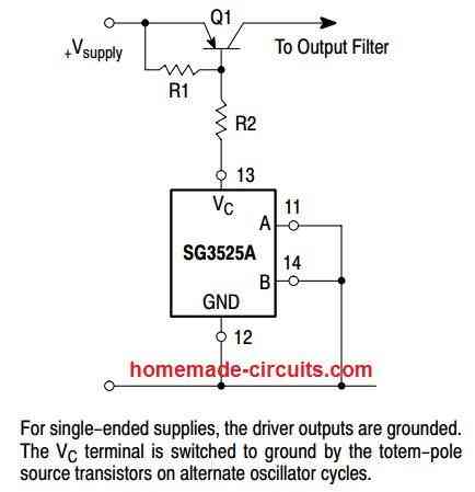
Swagatam,
Regarding the use of the SG3525 I have built an inverter which has a 32V output on the secondary side of the transformer and have used a bridge rectifier fed from it to provide feedback control. However, I have not been able to find any data on what voltage range to use to control the duty cycle of the SG3525. I am using a pot. at the moment and am getting a voltage range of 0.8V to 28V. Will this be sufficient to set up the initial operation? Obviously I don’t want to damage the chip in any way.
Hello Paul, the tripping point will depend on how much reference level is selected for the pin2 of the error amp. pin1 is the non-inverting input of the error amp, pin2 is the inverting iput of the error opamp. The pin1 is fed with the feedback from the output, once this feedback crosses the pin2 reference level, the IC will execute the PWM narrowing of the output.
Normally the reference at pin2 is derived through the 5V supply available at pin16 of the IC. This 5V can be subsequently reduced to some desired lower level either through a resistive divider or a preset.
Inverter Circuit with Feedback Control
Swagatam,
Thank you now I understand.
You are welcome Paul!
Hi Swagatam,
I have built the Design No. 1 – 2nd diagram of the “3 High Power SG3525 Pure Sinewave Inverter Circuits”. Problem is that I get no output signal on Pin 11 & 14. I don’t have a load on these two outputs at present. Does that matter?
I use a 12V battery as power supply and TR2 as feedback.
I have adjusted P5 so that I can get a low on IC1-10
Also P3 adjusted to give +2V Full wave 50Hz signal.
IC1-5 gives a saw tooth signal of +2.5V @8.6Khz
Pin 4 also gives a signal but is not connected.
I have replaced IC1, but still the same problem.
Please can you assist?
Regards
Jan
Hi Jan, is the IC oscillating? Please check the OSC out pin and check with a frequency meter whether this pin is producing the frequency or not.
You can also measure the same across the Ct capacitor.
For more details of the pinout you can refer to the following article:
Understanding SG3525 IC Pinouts
Remove the 741 Op amp IC and test the circuit again, you will get output this time provided that you built the circuit correctly. 741 low output is not 0 volt rather it’s about 1.3v or more and it’s enough to shutdown the SG3525 IC.
In the second diagram, the zener diode D7 is provided exactly for that, to prevent the IC 741 offset voltage
Sir! How to add the charging capabilities to this inverter circuit.
Please describe ????
You can add a an external battery charger with the inverter. When you connect the charger to the AC mains, it will start charging the battery.
Sir Please make a circuit digram on single phase shine wave inverter siganal convert to three phase signal generator for three phase shine wave inverter
Sir I have 2 inverter systems, first 1kva/24v, the other 3kva/48v both 400ah battery bank, but when I load at night with my freezer, why is it that the 3kva/48v runs down faster.
Suen, I can’t be sure why that happens without checking it physically, can be difficult to judge the fault…seems to be a specific fault with the 3kva inverter…
Thanks Sir, can’t be higher no load current than the 24v system
Sorry I did not correctly understand your question…
Hi, thank you for such a great article.
I want to make a simple sg3525 inverter (modified square wave) with a low battery voltage disconnect.
I want it to disconnect at 11.8V and reconnect at 12.6V and I want to know how to implement this. (The exact calculation of P4 and R9 according to the 2nd circuit to implement this Vth_low= 11.8V and Vth_high= 12.6V) or do I have to test it in real and vary the pot?
Also, what is the more efficient way to implement this low voltage protection: using an op amp as comparator as in your circuit or using a ne555 as a bistable latch (1/3 * vcc ; 2/3 * vcc etc) ?
Thank you
Hi, all the information is already given in the article…for the exact frequency calculations you will have to build it and the find the results by testing with oscilloscope and meter.
Please can two different power mosfet be used in an inverter circuit?
yes it is possible, if the power rating of the MOSFETs are in accordance with the load
Ing..pregunto
1- Sí se podría cambiar BC547/557 por BF 422/423
2- Al estar en funcionamiento el inversor ,,Qué determina el consumo del circuito sin carga osea sin uso, cuanto deberia de consumir….podría medir con un amperímetro desde la batería…?..y se supone que al tener una carga aumentara el consumo…
Mr swag pls I’m having a little problem understanding how to get 400hz from the values 18k50k present and 10k resistors along with a 1nf capacitor isn’t that value to small to get 400hz pls help me or is the sample above perfect for use
Mr.Ifeanyichukwu please don’t depend on formulas or the diagram, instead buy one oscilloscope or a frequency meter and check the results practically for setting up the frequency
Thank you Mr Swaggatam. I have been following your post and really want to thank you because they have been amazing.
The circuits above are really wonderful but could you please give us a design for 24V, 36V, and 48V 3KVA and 5KVA pure sine wave inverter.
And is there any anduino design for simulating the pure sine wave for use as the oscillator circuit in a 3kva or 5kva inverter?
Thank you Christopher, you can find a 48 V inverter in the following post:
1500 watt PWM Sinewave Inverter Circuit
You can use the following Arduino code for implementing as sinewave oscillator:
Arduino Pure Sine Wave Inverter Circuit with Full Program Code
Good day Sir, please what could be responsible for damage of fan used for cooling inverter
Hi Seun, the damage could be due to fan’s internal issues, not related to the inverter. Still you can try adding a voltage regulator through LM338 etc for the new fan to ensure better safety….
Please between 48v system using 4*40ah batteries and 12v system using 1*160ah battery which one is more efficient and why, Sir
4 x 40 Ah is efficient since higher voltage will mean lower current and thinner wires and smaller transformer
I am looking for your circuit that puts out 110ac and 220ac. I think it put out 5000 watts.
I want to build a solid state generator that gets the energy from the earth or the sky.
I want to hook it up to my main breaker box to run the house and maybe make the electric meter run backwards.
I saved your circuit, but now I can’t find it.
I’ve searched everywhere for the proteus library file for the SG3525 IC but can’t find it. I need to design and simulate my SG3525 inverter on proteus.
Help!!!
Sorry, I do not use softwares, so no ideas!
Please Sir, please how can I add a cold start to the inverter circuit
Seun, please explain the requirement elaborately
When I put on the inverter, there is instant surge, but a cold start will allow the inverter to come on without the surge
To implement this, the inverter must be switched ON without any load, once the inverter is switched ON, then the load can be switched ON, this will prevent the the inverter devices from a possible surge
Please sir, can you help me with the circuit diagram for 200W pure sine wave inverter?
Godfrey, the sine wave concept is already explained in the above article, you can easily customize them to your required specs
Please I want to find out information on the settings of the presets
Hi!! i made the circuit using pwm signal (ne555) but i am facing a problem.. When i connect a bulb (regular or led) the inverter works fine and leds doesnt flick at all.. But when i connect an appliance (laptop charger or a pc monitor) then immediately Mosfets blow up! could you please help me?
thanks!
Hi, what was the wattage of the bulb you used? Please try using a 60 watt bulb, and check the issue. I think your inverter lacks power. Also, make sure to use reverse diodes across drain/source of the MOSFETs and see if that solves the issue.
Try adding all the measures explained in the following post
How to Protect MOSFETs – Basics Explained
Thanks for your prompt reply! The bulb i used was 60watt and was working fine.. Not even got hot the mosfets.. I ll try the reversed diodes you mentioned.
OK thanks!
i put the reversed diodes as you told me. I checked first using a 60w bulb and everything was ok.. then i connected a 220/12v power supply to light a 12v bulb and now the explosion came from sg3525 and not from mosfets, so i dont think my inverter lucks power. Any other idea sir?
Thanks a lot
Please provide the details regarding the exact schematic which you built and what protection you used for the IC and the MOSFETs, and did you use a PCB or a breadboard?
i built the circuit you post its pcb but i built it in breadboard.. i add also the reversed diodes for mosfet protections.. now the mosfets arent blow up, but as i told you the ic exploded.. too strange.. could you please provide me gerber files of pcb if it is possible to constructed again in pcb?
thanks
For prototyping PCB is not required, but it should be assembled by soldering on a stripboard so that the connections are sound. The IC will need protection too, as indicated in the diagrams. The 12V to the IC must eb fed through a inductor or a 100 ohm resistor, followed by a couple capacitors and a zener diode. Please include the parts C16, C17, D3 and the inductor which will ensure that the IC is safe from any sort of dangerous transients:
" rel="ugc">
You cab replace the inductor with a 100 ohm resistor
I do not have the gerber files for any of the designs
Dear Sir,
I have lost job in lock down and trying to set up my own.
may i get some opportunity for pcb design also i can supply transformer any where in India( not ferrite core at this point of time).
Also i can supply Eletronics kit.
Regards,
B G Prasad.
Please sir, what cable gauge should I use for 5kva/48v inverter to be connected to the batteries, for positive and negative line.
Also, I used to use swg guage 13 for my 1kva inverter to run the parallel of drain and source of MOSFETs, please what Should I use for 5kva. Thanks sir Swag
Seun, 8 SWG looks OK to me for 5kva.
Hi Mr swagatam ,,I find this posts very educative and correct,sir I built the 3kva and it works fine,thanks to you..
But I have a problem with the simple alternative of 5000w u posted last..,I built it as designed but it just won’t produce an output,,,every other parameters are ok,,is there any error in the drawing sir,,bcus I’ve cross-checked over and over again,,even changed ic ,,it still won’t work
Thank you Mr MD,
Actually, upgrading an inverter to any desired wattage level is just about adding more MOSFETs in parallel to meet the wattage specs, along with upgrading the transformer and the battery accordingly.
So the last circuit does not specifically signify a 5kv inverter, you can use of the circuits explained above or anywhere on the internet and upgrade it to the required power output levels, by using suitably rated power devices, transformer and the battery
Ok sir thanks I understand now.,though my problem is that led indicates power is entering the circuit,,,but nothing at the output stage from ic to mosfets…..
Pls sir …….
I used your sine wave converter design and it’s so cool,so I tried it with 4047 circuit wich has a 0.22pin1 and 19kpin2,in parallel with pin3,,,,pins 7,8,9,12, to ground,,,and 4,5,6,14, to +12v,,,,,,it works but ic4047 dies when theres any little sparkle when connecting load (bulb)…..how do I stop this sir?
Pls help
Hi MD, you will have make the entire circuit stagewise. First you must try completing a basic 100 watt design and confirm its working. Once confirmed then go on adding the parallel MOSFETs, and increase the transformer/battery wattage, to increase the output handling capacity upto the desired levels.
For the 4047 IC, you will have to add a few extra parts across its supply terminals to safeguard it from the transformer back EMFs….and also make sure to add freeeheeling diodes across the transformer primary taps, or MOSFeT darin/source terminals. All these details can be found in this article:
https://www.homemade-circuits.com/500-watt-inverter-circuit-with-battery-charger/
Good day Swagatam, please does resistive load drawing 7%amps of the battery Ah have effects on the battery and the inverter, how sir.
Hi Seun, lead batteries can be discharged safely at 10% of their Ah rating, so 7% draw is fine, no matter whether the load is resistive or inductive.
Hello
Must the feedback transformer in the circuit must be 9v 100mah or is there any alternative
Can I use this circuit with 12v dc 7.2Ah battery.will it work then?
yes you can
Dear swagatam
Mosfets in my homemade inverter using sg3525 keep overheating till they burn even though attached to a heatsink.
And every thing in my circuit is connected right, what can i do to stop this pls
Dear Decipher, heatsink will not help if the inverter is accompanied with issues. Try building a basic SG3525 inverter module first, and check if it works normally or not. If still it heats up then the MOSFETs could be faulty. You can also verify by disconnecting the MOSFET gates from the IC and keeping the gates connected to their source pins via 1k resistors….
Dear Sir
Hello . I need a circuit to drive my ultrasonic sewing machin . The output must be 1000w sin wave 20 khz frequency. Can you guide me? I need high frequency AC . The output voltage is less 100 v . Thanks in advance
Hello Ehsan, what is the input voltage to the inverter, is it from 12 V battery?
Hi .the input voltage is 220 v AC
OK, in that case you will need to first rectify the 220V AC to 310V DC, then oscillate this 310V DC into the required 220V high frequency AC using the following full bridge driver circuit:
Simplest Full Bridge Inverter Circuit
Good day sir, Swagatam, I want to ask if 3 500watts/12v inverters are paralleled at the Ac side to power a 150watts freezer because I have over 1kwatts solar array for my 12v 100ah battery by 10am the battery is full and solar charges are wasting. Not feasible to get more batteries for now. Please advice sir.
Adeyemi, if you connect the AC sides in parallel and if one of the sides is out of phase may cause instant short circuit burning of the inverter, so this is not recommended.
Sir, between 220v and 200v ac output voltage, which one is better to set inverter for good efficiency and why sir
220V is the standard recommended AC grid value at 50 Hz, and therefore it is 220V which must be set at the inverter output.
Good day sir, which appropriate battery ah is good to do the testing of inverter at no load, because using 18ah, 40ah and 100ah batteries gave different readings of current at no load, why is it that
Adeyemi, that means there’s something no right in your inverter, because at no load all those batteries should have produced the same amount of quiescent current.
I just got the reason for the tripping off- sulphation because it was left for 4 months after buying, and used once without recharging and now trips off at 13.2v. I am off grid, so won’t it affect my inverter when I connect your homemade desulphator, trafo type. Thanks sir Swag
Hi Adeyemi, Batteries generally do not become bad in just 4 months, so you can try charging it in the normal method externally, with 10% Ah current, and see how it works. If possible include a float charge in the circuit. You can use 25% Ah current and then reduce it to 10% after the voltage has reached 13V
Hello Ing. Very grateful for your excellent circuits .. I cannot find information with termination N what I have
1- I would like to know the difference of the CI: SG3525 with SG3524 ,,
2- The SG3524B or N would be the same ..? since ending N is what I get
Thank you Felix, I don’t think the suffix has anything crucial, as far as the iC operation is concerned, so you can safely use any SG3524 or SG3525 variant for a specified PWM application
Hello, please can I tune this circuit to 30hz to us for my ac motor
Please check the datasheet of the IC, if it allows 30 Hz then you can do it.
Dear, Master Swagatam,
please, can I implemented the BJT buffer and the PWM circuit in a 3524 inverter circuit that I already built.
would it work, as its not a 3525 IC type used in your designs. What will happens if used.
Can you also hele implement this with a circuit diagram for me to see sir.
Abiola, the BJT buffer stage can be used with any oscillator circuit, so there’s no issue.
Good day sir,
Sir,i know your ability to extrapolate on practical from theory is undeniable ,i would like to know if Anas circuit above which you amended to sine-wave is a tested and workable circuit?.The circuit draft is to my liking….that i dont wnt to wast any component. is a feedback taken care- of in the design.
Thank you.
Good day sir
please how can i give the above circuit a feedback loop to maintain the output voltage? Thanks.
Parick, all the first 3 designs include an automatic feedback…
Thank you sir, Swagatam, for your educative site. Please I made a 3.5kw inverter with 72v battery input using 1 pair of high capacity mosfet of 600v and worked perfectly but any shake like just touching to test the voltage with meter, it blows up. Without shaking, it does not blow. All the solderings are firm. I have successfully made inverter with 36v input.
Adeyemi, there could be a short between the winding of the transformer, or somewhere in the connections.
The last circuit in this page tag simpler alternative, you designed R11 1k and c5 1u differently for both, won’t this cause imbalance.
You can ignore that, the diodes are enough to handle the reverse spikes, the design was referred from another source and the RC network doesn’t seem to be serving any crucial purpose
Please for 1kva inverter what is the maximum load it can carry
May be up to 900 watts
I’m a bit confused, an engineer just told me a 1.2kva inverter/12v can’t power a 0.5HP pumping machine of 375watts. I don’t understand. Please sir, Mr Swagatam, help me clarify.
Hi Adeyemi, I think you should request him to clarify the reason. As long as the pump consumption stays below 600 watts at full load, the inverter should be able to take the load.
Only during the switch ON the motor may consume upto 3 times more power, that could be a problem.
Please, I read that pure sine inverter (trafo based) consumes more energy than modified inverter, by what factor sir, thanks for your educative assistance, Mr Swagatam.
I don’t think that’s correct, because both are PWM based designs so their working principle should be almost the same.
Please how can I earth an inverter connection properly, thanks sir
You can connect the transformer lamination and the inverter chassis with the earthing line.
Please where on inverter chassis can I earth
Anywhere, it is supposed to be a metal chassis so position is not critical.
Can I use heat sink of mosfets because it is already earthed with the base of the trafo lamination, I don’t know where to earth for inverter, please sir, help out rainy season is here.
I won’t recommend earthing MOSFET tabs. You must earth only the negative line of the battery.
Please for clarity, are you saying I should earth trafo lamination and the negative battery line from our discussions. I am thinking it will cross react because of the heatsink which is a conductor.
Do not connect the heatsink with the metal body.
Please, how is that possible because the bolts that fasten the heatsink and the trafo are conductors. Please guide.
Sorry I can’t suggest on other prototypes, according to me the MOSFET should be kept aloof from the inverter body and the transformer body.
Please do u observe that the capacitor increases the noise level?
No it did not create any extra noise in my experiment.
It does so 5x here I think I will change the variable resistor from 50k to 20k to see what happens again.
Secondly, I have worked with many voltage regulators e.g. LM7815, 338, 317 etc their output voltage varies with the input voltage. Please I need something that can fix output at around 14v regardless of the variation at the input. Good hysteresis and surge.
Thanks for your prompt and constant attention.
God bless you.
Olamide, The sole purpose of a voltage regulator IC is to keep the output voltage constant irrespective of the input variations. If it is not doing this then either the IC is faulty or a fake one. Alternatively you can build your own customized regulator using the concepts explained in the following article:
https://www.homemade-circuits.com/simple-voltage-regulator-circuits-using-transistor-and-zener-diode/
Thanks a lot. I’ll try some of these designs. I currently have about ten used LM196 which have all gone bad. Most of the importers here bring components that have exceeded their shelve lives. God help us.
I have uploaded the source-code you shared on arduino and it compiled and ran well on my arduino uno. Please help me the circuit diagram of the complete design so my inverter can run on a micro-controller and a single transformer or any with C51/C52 family since I have the IDEs.
Thanks, GOD bless you real good.
Hi Olamide, you can buy these parts from amazon or aliexpress, they are pretty genuine. I am glad the code ran well, however, since I am not an Arduino expert, I may not be able to help you much in this field, I am sorry about that.
Sir, I encountered the same problem. Connecting a capacitor at the output increased the noise level and also the No-load current. why is it that way?
Mitech, connecting the capacitor at the output might increase the standby current slightly, but the noise will decrease, did you verify the noise with an oscilloscope? In fact, in many modified sine wave inverters, connecting an output capacitors improves the waveform, close to a sine wave.
Well done Mr. Swagatam. Can the same process that purifies the square wave to obtain basic sine wave be used to purify modified sine wave to obtain pure sine wave for better protection for very sensitive gadgets?
Thanks.
Olamide, you can use capacitors at the transformer output to purify modified sine waveform
Good day sir, please can I use 7812 regulator for oscillator input for the power supply for 12v inverter system, if I use any effect. Thanks Swag
yes it can be used, but add a 100 ohm resistor in series with the input of the IC, and also a 100uF/25V capacitor on both input and output leads of the IC
hi swag .i simulate the spwm circuit by using orcad and i get this result:
https://1drv.ms/u/s!AmpwfsAEQtshimD216KVSdKA_c9I
as the fast triangle wave has bias and the fast triangle wave is not generated correctly the comparator cannot compare the tow wave correctly and the spwm is not created.
the blue wave is the output of the op amp
the green one is the slow triangle wave and the red is the fast triangle wave.
i used exactly your design parameters in the simulation
Hi Sayed, you are right, because the two triangle waves are so different with their parameters, you have to make sure the triangle waves only differ in their frequency not with their dimensions. You will have to optimize them using an oscilloscope and by experimenting the part values of the astable. Moreover each slow triangle wave must accommodate no more than 6 fast triangles. The SPWM procedure has been also explained in the following article
https://www.homemade-circuits.com/how-to-generate-sinewave-pwm/
I have only provided the basic design concept for the SPWM, not the exact part values, the part values and waveform must be tweaked with an oscilloscope
Sorry I forgot to indicate that the same transformer and mosfets should be used for inverter and charging. At least make the circuit easy for me to analyze and construction. Also pwm should be integrated, thanks in advance.
The concept of relay changeover will be exactly the same as described in my earlier full bridge suggestion.
Sir I understand that with a 6000w inverter,more than 240A will be drawn from the battery,now my question is is there a relay that can handle such huge currents?
You can search it online….or use an equivalent SSR.
Hello sir swagatam,I have a 2200w rated refrigerator,a 2200w rated microwave oven ,4×65w fluorescent lights. Please I would like you to help me with an Inverter circuit diagram either using CD 4047 or sg3525 H-bridge that can run a refrigerator and be able to run also the other appliances which totals to about 6000w. Also the Inverter should have a feedback for low battery cutoff and battery charging system. I have a two wire (non centre tap) 6000w transformer,2×12*200AH batteries and am planning to use irf064 as my mosfets.
Hello Evans, I have already provided all the details in the above article and also in a few other related articles, you will have learn them step wise and then integrate them to get the intended design… You must first build a small prototype and then gradually upgrade it to a more powerful version.
hi swag, the design with the spwm can support a load above 1000 W ?
Sayed, the pwm is only for the waveform, the power is determined by the transformer, MOSFet and the battery, which can be customized for any desired power
hi swag,tanks for quick reply.i was testing the spwm stage,i built the astable 555(fast triangle wave) and i get this waveform 🙁https://1drv.ms/u/s!AmpwfsAEQtshil8otxdxMJymsU8j)
why the wave had a bias ???
Hi Sayed, it’s because the IC 555 capacitor charge and discharge happens between 1/3rd and 2/3rd supply levels.
so the comparator dont work properly in this case !!!!
It will work properly and create the PWMs perfectly…
Found it very attractive ,thankyou
Engr. Good morning..please do you have a circuit diagram that can boast my phone’s signal. We have poor network in my area thanks..I always find it difficult to browse Internet..thanks
Sunshine, please post the comment under a related article, please see the message which I have put just above the comment box.
Good evening Mr. Swagatam,
Can I use a ferrite core transformer for this inverter? If so what should be the volts per turn?
Gamini, ferrite transformers will require strict calculations as I have explained below
https://www.homemade-circuits.com/how-to-design-and-calculate-ferrite-core-transformers-for-inverters/
thanks for share
Sir, I have constructed twice your first design successfully. However I want your help regarding the following problems.
1. Since I couldn’t get 330k pot I used 200K pot in series with 100k (R2)
instead of 1k resistor. Is it Ok.
2. I extended the circuit wit your battery charging circuit using lm358.
3 Now I am using 18 amp battery.
4. Now my problem is in my second attempt, the battery cables are
getting heated, with too much noise from transformer.
Pl.help me sir, What would be the problem.
Your, faithfully,
Leelesh.
Hi BK,
Yes 220K will do instead of 330K
Is the inverter working OK without the battery charger? You must check and verify the two stages separately and only then join them together. I will have to see the schematic to be able to troubleshoot your problem. You can it send to my email.
The problem that you are facing clearly indicates a short circuit across the MOSFeTs, due to blown MOSFts.
Shalom,
For transfomer with 26.8-0-26.8, what will be the battery voltage if i design my circuit with SPWM
The battery voltage can be around 36V
Good job brother..
I have tried to build the SPWM circuit,
The readings are as follows
1. Fast wave frequency = 350hz,to pin 3 of lm741
2. Slow wave frequency = 50 hz,to lm 741 pin 2
3. Output of lm 741 pin #6 = 50.44Hz
4. Frequency of both Mosfet gates = 25.22
5. Sg3525 pin #11 &14 Voltage is 5.3 each
6. Output frequency of Transformer = 50.33Hz
7. Transformer 26-0-26 primary /secondary 235V power of transformer is 6KVA
8. Input voltage to transformer =33
9. Input to oscillation is 12Voltage
10. Transformer sound normal,seems everything is ok but….
PROBLEM
Output voltage Multimeter reads 1.988Voltage,
What could be a reason for such low voltage while transformer is sound like everything is ok?
Thanks Jackson, I would suggest you to first build the basic 50 Hz inverter without any PWM and verify its normal working with optimal loads. Once confirmed then you can try integrating the PWM for the final results. You may need a scope for this, only frequency measurements might not be sufficient to troubleshoot faults if any.
Jackson
(1)you need to put a 5kohms preset from the output of the SPWM circuitry before it get to the base of it BC557 transistors so that you can be the one to set your output voltage (ie from the transformer output) or
(2) you interchange the connection of the fast frequency and slow frequency that is getting to the opamp (ie connect the slow frequency to the point that you connected fast frequency and take the fast frequency to the point that slow frequency was connected before ) with any of this solution you will get your output voltage but the second option will not set the output voltage if want to set the output voltage you can go for feedback system or you put a preset at the output of the opamp before it get to BC557 transistors. Don’t forget to include a capacitor at the output of the transformer the value should be 185 or 155 by 400volt, I hope you know how to connect the preset if you don’t know it goes this way the right pin# is connected to the output of the opamp then the middle pin# is connected to the base of BC557 transistors and left pin# is to the ground that is all.
Good morning sir…Engr. I hope you are fine.
Please I want to step down 24v DC to 12v DC 5A please help..I tried it using MOSFET and 7812v but it gets hot so quick..thanks
Sunshine, linear regulators will heat up since they will be dissipating the excess voltage into heat during the conversion. You will need a buck converter for this if you wish to get it done efficiently…there are many buck converter circuits online you can find.
good morning sir..thanks for answering my previous questions…engineer please I need FM radio transmitter circuits diagram…I got some in your blog but I don’t know how to increase the ranges/distance.. Frequency variation if possible. Thanks so much…
Hi Sunshine, any range beyond 200 meters will require special antenna and optimizations.
You can use the following concept to get up to 200 meter range
https://www.homemade-circuits.com/homemade-walkie-talkie-circuit/
Hey shalom…could you please help me outdru with how to interface the egs002 with the sg3525 man…
Okay thanks a lot.. But sir, is there any formula regarded to this issue..for better calculations? Assume
my house total load is 800w,
inverter 1kva,
run time 8 hours.
.battery ah…?thanks
Hi Sunshine, I already have an article which you can read and calculate the parameters as per your exact specifications:
https://www.homemade-circuits.com/how-to-calculate-and-match-solar-panel/
Good morning sir…how do i calculate battery’s voltage and current to know the solar panels that can charge it., and how long battery can stay for inverter during using in house thanks
Hello sunshine, The voltage must be at least 6V higher than the battery specs, and the current 5 times less than the battery Ah for a lead acid battery. These must be checked at peak sunshine, with no load connected. The discharge rate of the battery should be 1/10th of the battery Ah value, then it may provide a back up of around 7 to 9 hours.
Good morning my able tutor please
I have another question which is how will i set the output voltage of the inverter if I’m using SPWM circuit with the SG3525 circuit
Thanks
Hello Emmanuel, it can be done by adjusting the dead time value of the SG3525 IC
good morning brother..Engr. I built this inverter circuit using SG3525 with sine wave conversion…is working, but the MOSFETs IRFP150N *4 with heat sink heats up immediately, if no load and when loaded. Please I need your direction.. Thanks may God reward in with good things abundantly
Thanks sunshine, please replace the existing NPN/PNP BJT output set up with only NPNs, as shown in the following diagram, and then check the response:
" rel="ugc">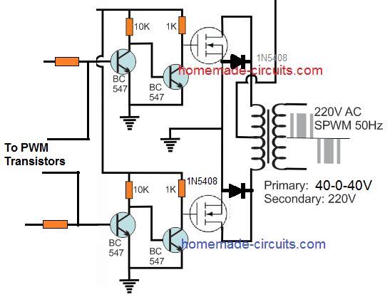
I thought that the 1k resistor suppose to be connected in get to source in which is ground not get to positive
grounding is done by the transistor. Any extra resistor across gate source will not make sense in the above linked circuit.
Alright sir thanks a lot for your support and god bless you for your good work
My pleasure Emmanuel
Hi swagatam
I really like your article a specially that true sine wave inverter circuit that uses the combination of SG3525 and 555timer ICs but is like the SG3525 circuit is giving high frequency and also the 555timer circuit is also giving high frequency and if so what will be the total output frequency in the output of the transformer and also i would have love to see the simulation of the wave form of this circuit
Thanks
Regard
Thanks Emmanuel, the inverter output will be stabilized by the transformer which will be equal to the SG3525 frequency. You can add a few capacitors at the transformer output to stabilize the output perfectly.
And also can i used pure sine wave signal generator circuit to feed in the place of PWM signal to the SG3525 BJT circuit
No, It should be in SPWM form, not exponential, ….only spwm will work
Okey thanks
Helo sir,am having concern for my feedback.Whenever I on my inverter ,I noticed the feedback always drop,pls what can I do ?
Hello Akinbi, Feedback system will not work if the load current exceeds the battery’s maximum limit or if the battery voltage becomes low. It will work only when the battery is optimally charged and the load is within acceptable limits
Have not done any work at all based on your post but just going through it gives me enough vibes…..thanks boss, you’re doing a great job????
Glad you liked them, wish you all the best!
Please between using rectifier at the inverter output and rectifier at mosfet line to send feedback to pin 1 of sg3525, is better for automatic voltage regulation
From output is better, and should be through an opto-coupler
Please how can i use optocoupler circuit, any circuit
2. From 3kva Anas’ circuit, for pin 11 &14 10k resistor connected to the ground, what is the relevance, and is it necessary
It’s a good practice to add grounding resistor across base/emitter of any transistor. where do you want to add the opto?
Please what is the likely standby current draw for a trafo based and trafoless 1kva inverter. Thanks
A trafoless inverter will have negligible standby consumption compared to a transformer based inverter
Please what can i do to the sg3524 ic i use, yearly during raining season, it usually develops fault due to lightening, and thunderstorm which i replace.
Try connecting the inverter body with a good earthing connection.
Hello Swag deos the SG3525 can work with a 7809 voltage? my sg3525 cant work under 12VDC!
thank you!
Hi Mathieu, SG3525 will work with 12V and also with 9V, something may not be correct in your circuit!
Dear Swagat,
I tried the basic circuit with a salvaged trafo of my ups, 4XZ44 mosfets and 7AH battery. The osc frequency is 51hz,50%duty cycle. Driver is Pnp/npn pair as per Yr circuit schematic.
But the mosfets blew up.
Checked the ckt and replaced the mosfets.
Now powered through a series bulb 21w,12v and circuit worked with 185 V out put. Loaded a 9w led bulb and it worked. Voltage drop at bulb was 6v. Connected 2 freewheeling diodes too. But when direct powered, the mosfets blew again.
Pl advise. Is there any snubber issue?
Dear D K Mishra, MOSFETs can be very unpredictable and can blow without apparent reasons.
You can refer to the following article, and possibly apply all these protections to your MOSFETs:
https://www.homemade-circuits.com/mosfet-protection-basics-explained-is/
By the way what is the specifications of your MOSFETs? I tried to find the datasheet of 4XZ44 but could not find any…did you mean IRF44Z?
Alternatively instead of MOSfETs you can try a combination of TIP122 and TIP35 BJTs which will never blow unless the base is shorted to positive line.
Hello creative Engineer please how can I have stabilised voltage regulator for my oscillator at peak sunlight because there is increase in voltage at pin 11 and 14 which causes output voltage instability of the inverter. I have used zener, transistor, 780x as regulator but not difference .
Hello Victory, 78XX will definitely stabilize the voltage to the oscillator and its frequency. The output may be increasing due to increase in peak voltage to the transformer, which you can control through a feedback control system.
the day, I did the inverter from the last schematic and I have a very disturbing noise at the transformer, is it normal? which would be solving for less noise?
Tks
Do you get the noise without the IC 555 PWM?
I did not try without 555 am
loaded directly with 555 and 6 transistors for a pure wave inverter,
I tried an electric motor and it sounds the same sound.
Disconnect the IC 555 PWM link from the BC547 transistors, and check whether the sound still occurs or not?
can I get only 555 from the socket or should I give up 10k resistors of pins 11 and 14 and to connect the mosfets directly from sg?
If you have used a socket for IC 555 then removing from the socket will be enough
Please, can you give me the full circuit with H bridge with oscillator like sg3234
hi swag, i built the 3rd circuit (the one used in pcb) without the pwm stage.and i get this output
https://1drv.ms/u/s!AmpwfsAEQtshgnPpqeCDab6Ivu_Y?e=3zSG8j
where is the problem?
Hi Sayed, it will be difficult to guess because the 3rd circuit is a tested design and a standard 3525 circuit. Please check the waveform across the output pin of the IC, it should be perfect rectangular waves.
hi swag ,thanks for your quick response.the waveform across the output pin of the IC is showed in this link:
https://1drv.ms/u/s!AmpwfsAEQtshgnQom2w4J8HWeepG
Hi Sayed, it looks perfect, the output may have harmonics and that’s why it may show some interference. You can connect a 2uF/400V capacitor at the output and check again
Hi swag,with 2uf capacitor at the output ,the output waveform looks like this:
https://1drv.ms/u/s!AmpwfsAEQtshgnVdP0sNbxAWeKJD
Hi Sayed, it looks much better now!
yes looks better but with high p-p voltage!!
The peak will depend on the winding of the transformer. It should match the RMS or the average PWM produced a the MOSFET drain. If suppose trafo primary is 9V, and the RMS is 10V, then output will not be 220V, it will be 244V
i build the circuit without the pwm stage and i used a 12-0-12 trans
You can decrease the output peak by adjusting the PWM
Hi Swag thanks for the wonderful work.
I intended using it for battery charging also but the transformer voltage is lower than the battery.
Please help.
Hi Frank, are you using a center tap transformer for the inverter? in that case you can use the outer wires of the transformer for the battery through a regulator.
I got same waveform at no load using oscilloscope. On connecting a load, the waveform will change to a Better shape.
Please sir, why is important for transformer output to give about 310v before voltage correction. At times my trafo output could be 270v before correction
Victory, it is to ensure a plus margin for the feedback regulation. 270V is also OK although it may provide lower range of feedback stabilization.
Hi teacher Swagatam I want you to check this for me please
if the 741 cut off is base on input low voltage then
what will happen if using 24v and 7812 for driver circuit? how would you configure the 741 under this teacher because the 7812 will also Serv as steblizer if even battery voltage should drop to 16v
the 7812 will still maintain the 12v out put to the driver circuit and also the 741
Hi Osei, to solve the problem quickly you can use LM321 or LM358 which are rated to work with 32V.
For 741 supply the 7812 only to the pin#7 of the IC, the inputs can be directly connect wit the battery supply. For the inputs use a 10K for the zener diode, and 10K in series with the preset, this will ensure that the input pin never gets 12V while adjusting the preset.
Thanks for your quick response
If I understand you teacher,
741 pin 7 to 12v and the inputs configuration can be contacted to the 24v per my power is this ok teacher?
If I should go for 321 then pin 5 can link the 24v per my power and the remaining configuration remain the same ok teacher ?
Thanks teacher.
yes that’s right, just make sure to add 10K in series with the positive side of the preset for IC 741
I hear you teacher and thank you very much.
Sir Swagatam my greetings, I was away for sometime but I’m back and I just missed your teachings thanks teacher.
No problems Osei, please keep up the good work!
hi swagatam , which circuit is fully tested that i can use it?
Hi Sayed, all are fully tested you can choose anyone as per your preference.
hi swag, i built the 3rd circuit (the one used in pcb) without the pwm stage ,the frequencies of pin 11 and 14 was not 50hz , i changed rt and ct to get 50 hz and i get tow nice square waves from pin 11 and 14 ,but when i add the mosfet stage ,without any load the mosfets explode.
I added a 0.33ohm resistor betwen the drain and the trans end , the circuit worked and i get in the output a wave similar to square wave (with some overshoots) with 400v p-p voltage and 186v Vrms
and the 0.33ohm resistors get hot quickly where is the prob?
Hi Sayed, MOSFET behavior can be tricky to predict. You can read the following post to understand how to protect it from various situations:
https://www.homemade-circuits.com/mosfet-protection-basics-explained-is/
You can employ the procedures explained in the article. The 0.33 inclusion is not correct as that would prevent the inverter from operating in normal conditions.
so the circiut that i used can works properly without the pwm or spwm stage?
and check the rt and ct value in your post cause with that values the waves generated are not 50hz
PWM or SPWM are optional stages which allows us to get better optimization of the output, you can avoid them if you wish, and make an inveter using basic SG3525 circuit. You can tell me the Rt/Ct values, I’ll mention them in the article.
Great designs. Great ideas. Thanks
Thank you!
Good day sir please sir my inverter feedback is not working when ever I connect load to it the output voltage drop I check the voltage at pin 1and 2 of my sg3524 it 5v and 2.4v respectively please what could make the feedback not to work
Faith, if the load wattage exceeds the transformer or the battery wattage then the feedback control will fail to work, please confirm this!
How to calculate MOSFET in pallarel or how to know number of transistors that will give me 1500w for inverter
Multiply the IDS and VDS of the individual MOSFETs, and add them, this will give you the maximum tolerable power of the MOSFETs combined. Make sure the margin is at least 10% higher than the required power output.
The feedback can work well when you use a transformer that can give output voltage that’s more the output you want the inverter to give without connecting the feedback yet. Let’s say Your transformer gives 250v above without feedback then when u connect feedback, u can now scale it down to 220V but if your transformer gives 220v without feedback, on connecting feedback there will be no regulations unless you need voltages that’s below 220v.
If the load exceeds the transformer wattage, then the feedback won’t work and the output voltage will drop below 220V, no matter how much excess margin you may have.
Hi teacher Swagatam, is it possible to apply full bridge to any of the circuit provided especially the SPWM inverter circuit . Teacher what should be the way to go about it if possible
I have started working on SPWM and I will alert you the outcome
thanks teacher
Hi Osei, it is possible, you can chop the low side MOSFETs with the SPWM. you can see the example in the second circuit below:
https://www.homemade-circuits.com/5kva-transformerless-inverter-circuit/
In the first circuit you can apply the SPWM to the 4N25 opto transistor base
Thank you teacher
Sir that’s exactly what I did the inverter work well no heating nor noise but frequency is high not 50hz as expected so my question is what
Frequency range should I expect
Please measure the frequency at the output of the transformer, it must be equal to the slow triangle wave frequency or the frequency at pin#4 of SG3525 (50 Hz). The fast triangle wave frequency can be around 400 Hz.
Hi teacher Swagatam i was looking into the modefied circuit posted by Lynch which I think is from your 3kva inverter circuit . l could see many changes in his post . please explain this to me.
1.what is the name and function of the parallel circuit in series to the 100uh to 12v supply voltage.
2. 100 instead of 470 ohms between pin 5 and 7.
3. two 10k between out put pins 11 and 14 to ground also omitted.
Teacher, what significant changes does it bring to the function of your 3kva circuit
4.10k from pin 2 to ground omitted.
5.function of capacitor connected to pin 9 and ground
can this circuit also work under 12
to what supply voltage?
and if I want to go from 3 to 10kva what
changes should be made
6. spmw and pmw which one is more efficient
Hi Osei,
The inductor is for suppressing interference from the transformer into the circuit to ensure the circuit works smoothly.
The parts at pin7 and pin5 decide the frequency, different combinations can be used for getting 50 Hz.
the 10K are not compulsory, but you can use them for increased safety of the mosfets. They have nothing to do with the 3kva function.
Pin#2 is the non inverting input of the internal error amp, which needs to be supplied with a reference voltage, the 10K is probably included to adjust this reference value.
Pin#9 is not crucial, it is for introducing hysteresis for the error amp, and can be ignored.
Maximum operating voltage of the IC is 35V.
SPWM is more efficient
Thanks teacher for your quick response. So if i use the circuit posted by Lynch I can still run 3kva to 10kva ? .
Teacher if I want to go for high power then the changes should be on the transformer, battery and fet transistors leaving the driver circuit as it is .
Is that ok teacher?
Thanks .
That’s correct Osei, you can use any of the designs for getting any desired power output, just by upgrading the three elements.
Hi
the SG3525 that comes from various cheap inverters on ebay control the output power by adjusting the duty cycle of the mosfets right?
I ask that because when I measure the signal on the mosfet’s gate I see full dutycycle even when there is no output connected and the input current is almost nothing… what Im missing???
I always suppose that u control the output with the DC of the mosfets but as I see that is not the case with the SG3525….
Hi,
The duty cycle can be adjusted either by a variable resistor at the respective pin, or through a feedback from the output.
So it will depend on the above two factors. If you have a variable resistor at the PWM pin, then you can vary it and check the results.
MOSFET drain current can be efficiently controlled by PWM control and not by linear DC levels, because lowering DC at gate can heat up a MOSFET
thanks but why the duty cycle is the same with full load and with no load?
all the current pass inside the SG3525 ???
I have monitor the gate signal of the Mosfets with a Oscilloscope and it is the same with or without load….
Please tell me it is an error to replace a 60v/120A mosfet on a inverter with another mosfet of lets say 500v/120A?
there’s nothing wrong, but MOSFET rating ideally should be as per the battery specs, otherwise the energy conversion will not be efficient.
It will be the same unless you apply a feedback circuit from output to pin#1, as shown in the following first two diagrams:
https://www.homemade-circuits.com/sg3525-pure-sinewave-inverter-circuit/
thanks for the answers… I see so if u are using 12v batteries it is obvious that u need near 12v mosfets… 500v mosfets have much higher internal resistance making it less deficient…
It is my mistake not to clarify that Im talking about the circuit on a cheap aliexpress DC-DC step up module.
I suppose that after the mosfets there are additional transistors that allows current to pass controlled by PWM that use the output feedback… I see a MCR100 near the end bridge rectifier… it is tiny but controls up to 600V… I suppose they let the mosfets with a constant full DC and controls the output with that SCR.
Very cleaver but I wonder if it is better than just change the DC on the mosfets gate.
Can’t say much about it! It will be difficult to suggest without seeing the full schematic diagram of the circuit.
Hello my teacher, my appreciation 2 u 4 your good works and support, I just finish building 1000w which is 1kva from this your nice circuit and it’s working perfectly well, i use a 2000w transformer 12v- 0 -12v IRF540 x4 and am using 75ah x2 batteries and the ouput is very stable and it’s handling 800watts of load from my calculations and when the 2 battery’s his fully charged it only gives me back up of 2 hour 30 to 2 hour 45 minutes and i only make use of it in the day time which means i do not need a reserved better because i closed 6.00pm everyday, please teacher i don’t know if it’s possible to get a solar panels that can back the load of 800w without having to charge the battery with generator, if yes, how many panels and which Watt’s should i go for? Please sir i really need your help because there’s no electricity here and i waste a lot of money to ⛽ fuel my generator. Thanks my regards.
Thanks Andrew, I am glad you could make it successfully.
800 watt solar panel is possible. Calculating solar panel is actually very easy, if you read the following article you will be able to calculate the right panel as per your available specifications
https://www.homemade-circuits.com/how-to-calculate-and-match-solar-panel/
Let me if you encounter any doubts.
Thanks 4 your quick respond, i now understand how 2 choose the right solar panel, battery’s charger controller and lot more about all the calculations, please keep up d gud works and thanks once more.
You are most welcome Andrew, please keep up the good work!
Good day sir, I have built 1kva,please I wanted to build a 200va trafo based inverter(modified). I used a 7Ah battery, the trafo coil guage was G20 swg for both primary and secondary. The max output voltage was 80V with load, with 60w loa it dropped to 28V. Please advise on what to do and the causes of low voltage
Glory, Both side winding can never have similar wire gauge. It will be according to the current of the winding, consult a transformer designer!
Please sir I need a simple schematic diagram of 3kv inverter, because that one in this post have 2 diagrams and it is confusing me.
Christ, You can try the following circuit:
https://www.homemade-circuits.com/48-v-inverter-circuit/
Hello teacher, first let me say a big thanks to you, Three ★** 4 u???? I build #3design 3kva without any problem, i use x10 IRF540N 48V 0 48V transformer 12v 100ah battery x4 but i don’t know how to calculate how many MOSFET i should use. Please teacher i want to know if i could build a smaller watts like 300w, 500w to 1000w and how to make the change, if it can be done, what should i do?
Glad it worked Andrew, that’s wonderful!
You can definitely smaller versions by using just a single mosfet instead of many in parallel. Please read the following article, it has all the details regarding the calculations required for selecting the mosfets for a desired load.
https://www.homemade-circuits.com/how-to-calculate-and-match-inverter/
Thanks for more diagrams can i buy pcb circuit (sine wave)from you now so how can communicate to you cause i need pure sine diagrams with sg3525 chip thanks
Thanks selemani, glad you liked my diagrams, however I am sorry presently I am unable to provide PCB designing help due to work load, I hope you will understand!
okay sir pin 11 =6.03v and pin 14 = 6.03v,,,,do you meant that I should make the transformer primary 6-0-6 and the secondary output 220v? I already made my transformer 9-0-9 and 0-220..I want to make 1000w inverter…
Sorry Sunshine, there’s a slight confusion. Since duty cycle is 50% for each cycle, 6V corresponds to 100% duty cycle for each output, for a 12V battery….so your trafo should be 12-0-12V, but 9-0-9 is also OK.
Now make sure the current of the battery side of the trafo is high at least 10 amps.
God bless you abundantly sir for your I have built this circuit 3 times without any problems, but I’m building another one and if I reduce p2 it gives voltage of about 100v but if I increase it it damage 3525 and if I pls sir I need your help.
Thank you Kayode, can you please show me exactly which 3525 circuit are you building?
P2 is only for setting the reference value for the error opamp (which has a high input impedance), it cannot cause any damage to the IC. It seems your IC is duplicate or is a faulty one.
Hi Kayode, connect the supply voltage to the IC through a 100 ohm 1 watt resistor, and make sure to connect a 100uF/25V across the supply pins of the IC, and also add a 12V 1 watt zener across these supply pins. this will prevent your IC from blowing repeatedly.
Tnks sir, I’ll do that and give you the feedback ,
1. Pls must the c1 be mkt type or can we use the ceramic disc type?
2 pls is the auto correction for maintaining the set value so that it doesn’t go beyond or below n because , I don’t have a stable voltage, it drops while increasing load, to about 170. . Pls what do I do to get a stable 230v.?
3. The output of the 741 ic shuts down the 3525 gradually thus making the output of the inverter gets lower slowly till it dies, I have used the 4007 diode forward bias to the 3525 #10, all is about the first design, tnks sir, awaiting your reply .
Kayode,
1) C1 should be MKT preferably, although ceramic will also work.
2) If your output is decreasing with load, it means your battery current is insufficient to handle the load. The auto correction can never increase the output. The auto correction can keep the output constant only as long as the load is within the battery limits.
3) The operation is correct, the output will go down slowly when pin10 is held high continuously
Hello sir, pls under circuit design one, you posted another circuit with automatic feedback control with the title “Another Design with Automatic Output Feedback Correction” just before the begining of the explanation of circuit design 2. All I want to ask is that can we use the feedback control mechanism they used there in any sg3525 inverter circuit for the feedback control.
Like the sg3525 inverter diagram I have I connected the 4 diode bridge rectifier across the transformer as they did here and from the first wire of the rectifier I connected 5mh which went to 10uf capacitor and from the capacitor to the ground, also from that same wire from the rectifier I connected 56k Resistor and 1k Resistor, the subsequent wires from the 1k ohm went to the first pin of the sg3525 of my Inverter and to ground, the remaining wire of the rectifier went to ground. Also the the ground here does it mean to the negative side of the 12v battery. Pls will this arrangement work for my inverter and any sg3525 inverter as regards to feedback control. Thank you.
Anthony, all the ground symbols refer to the negative of the battery, so you must join all those wires together, and connect the negative of the battery to the SOURCE terminal of the mosfets. You must connect the feedback system exactly as shown in the diagram, it will work. In place of 56K you an use 100K, and in place of 1K you can use 2K2 resistor for better safety.
Thank you sir for the reply
Sir pls can I use this feedback control mechanism in any inverter or only in sg3525 inverters
No problem Anthony, you can use the op amp feedback circuit with any and all inverters provided their output devices are N type.
good day sir,, engr. I built the 3rd circuit above..there is output voltage from ic, I connected MOSFETs with 12v ups transformer but the output voltage from the transformer can’t power any load,,, okay I made the battery 24v it powers 100w bulb if I put another load the voltage comes lower pls help..my battery is okay…
Hi Sunshine, please measure the DC voltage at pin#14 or pin#10 with respect to ground. The transformer primary rating should be ideally equal to this value. Randomly changing battery or transformer can damage something in the circuit. Also the current delivering capacity of the transformer should be high, above 10 amps.
good evening sir, thanks for your post, please sir , I built the above inverter I mean that of Anas though I used all the modifications built when ever I connect transformer the MOSFETs get heated immediately, I have damage lots of MOSFETs and I have checked for errors but can’t fine any, though I didn’t consider the resistors wattage. I used20k preset instead of 22k, 50k instead of 47k and I used a 650 watts ups transformer and irf3205 MOSFETs please I need your help
Hi eric, please try the 3rd circuit in its basic form, once its working is confirmed then you can upgrade the mosfet stage with the BC547/BC557 stage and more parallel mosfets.
If still the mosfets burn then the problem could be somewhere in your circuit layout.
Resistor wattage or slight preset value changes should not have any effect on the working of the circuit
Please, is waveform different at different inverter voltage output.
It may vary a little at different voltages.
Good morning Sir…thanks for your regard, question about the transformer, I’m using 200w super Master stabilizer’s transformer,guage20 for 220v o/p side and guage12 for I/p side…..should I wind the input side 9-0-9. OR 12-0-12..and separate winding for the battery charger like 18v…for 12v Inverter… Or can you direct me here, like the turns for primary side and secondary, what wattage could such transformer give? Thanks Please don’t be upset for my disturbance.
Hi Sunshine, the winding for inverter operation can be 9-0-9 for a 12V battery, for the charger you can add a separate 0-12V winding, having 10 times lower current specs than the battery Ah rating.
Thanks so much I really appreciate.. God bless you..i will try this with the pure sine wave conversion system…I like your company..
You are welcome!
Okay thanks.. Please help me with any good inverter circuit that can power small refrigerator.. May God reward you with good thongs
You can try the second design from this article, this is an universal high quality sine wave inverter suitable for all appliances.
https://www.homemade-circuits.com/arduino-pure-sine-wave-inverter-circuit/
good morning Sir… u have not replied my text..
good day ENGR. thanks so much for your love and help…. I built the Inverter u Posted using SG 3524 pwm…is working the output voltage 220vac but is not stable, if I vary it sometimes it will be stable sometimes it will be blinking… what could be the issue?…. please I want to build Inverter that can power refrigerator…which circuit can I use please help..thanks so much my regard to your company friends and families.
Hello Sunshine, if the output is fluctuating rapidly then there could be some problem with the configuration or one of the components, it can be difficult to troubleshoot it without a practical testing
Hello my friend, I build one of your inverter circuit with 4047 ic. And it works perfectly. I want add this feature that will switch off the inverter when battery is drain to 9 or 10 volts.
Hi Ade, you can try the last circuit from the following article:
https://www.homemade-circuits.com/low-battery-indicator-circuit-using-two/
I meant any way to use the freezer with the 720w panels and bad 36v batteries and the inverter. I even used stabilizer with it, still it didn’t work
you will need a mppt or a buck converter controller, then you use the panel directly with the inverter
I use pwm charge controller, please how is mppt better, I live in the tropics and at peak sunlight, I get about 13amps. Please explain
MPPT will try to keep your output IxV as close as possible to the input IxV, you can also try a buck converter flyback type
Thanks creative Engineer, please give me a circuit to mppt and buck converter. I enjoy your educative site, thanks.
Thanks Grace, you can try the following design:
https://www.homemade-circuits.com/5v-pwm-solar-battery-charger-circuit/
sir i have a modified sine wave driver using 555 and cd4017, i want to build a inverter with my transformer 1000va single 12v with 220v. what circuit do i use and how many mosfet to use. thanks
Thanks sir for the reply. What of if I increase the number of panels with the pwm charge controller. Will it work with my freezer.
I cannot tell until I know how your PWM controller is designed to work? Is it a buck converter or just a simple duty cycle based design??
I meant factory made pwm solar controller.
what is the output and input voltage and current specs of the controller?
36v/30amps pwm charge controller
Again, if it’s a buck converter then you can use it. Meaning it should be able to convert high voltage/low current from the series panels to low voltage high current for the inverter
Hello sir, I read an article about rural mini-grid solar project in my country, and the claim was that it will be used by households with Electric stove and many heavy loads. To pay using prepaid meters,
I want to ask is it sustainable with heavy loads,
2. Can it be cheaper and cost effective than cooking gas.
3. Is solar system cost effective for heavy loads than utility.
Hi Grace,
Initially the setup may look too costly, but in the long run it may pay off. But it may take at least 5 to 10 years to actually recover the initial cost.
Thanks Chief Engineer, please how this inverter circuit do power factor correction.
Hello Grace, PFC is not included in these designs, these are just basic inverter modules.
Please any circuit on PFC.
It will require some complex calculations, I have not yet investigated this subject so can’t suggest much. Here’s one article which you can refer:
https://www.homemade-circuits.com/power-factor-correction-pfc-circuit/
Thanks for the circuit, does PFC in inverter important, your advice
If you want to use it at home then it’s not important, but for manufacturing or commercial purposes it is very important.
Sir, For manufacturing, do you mean, mass production of inverter for sale or what. Also, what do you mean by commercial purpose. Thanks
It means not for your own personal use but for the masses or a 3rd person (for sale)
Thanks for being resourceful sir. Please presently I am using 36v/2.5kva inverter with solar panels, which used to carry my freezer, but now the batteries are bad, is there anyway I can still use the freezer, only my fridge is working, I am totally off grid.
I have tried using your triac circuit for inductive loads, not working.
At peak sunlight, still not working. Freezer is new
Any advice please.
Thanks Grace, Can you please specify your exact requirement? Are you trying to control 36V with a triac? Triacs will never work with DC.
I meant how to build 120v/10kva inverter using 10batteries. Most importantly the smps power supply for the oscillator section, stepdown 120v to 12v for the oscillator
If you are using 10 batteries in series then you must be getting one positive end and one negative end from the series connection? You can take the positive from the battery which has its negative as the ending terminals and use this battery’s positive for your circuit.
See the battery series at the top side of this image…see how the positive is extracted from the left end of the series for ICs:
" rel="ugc">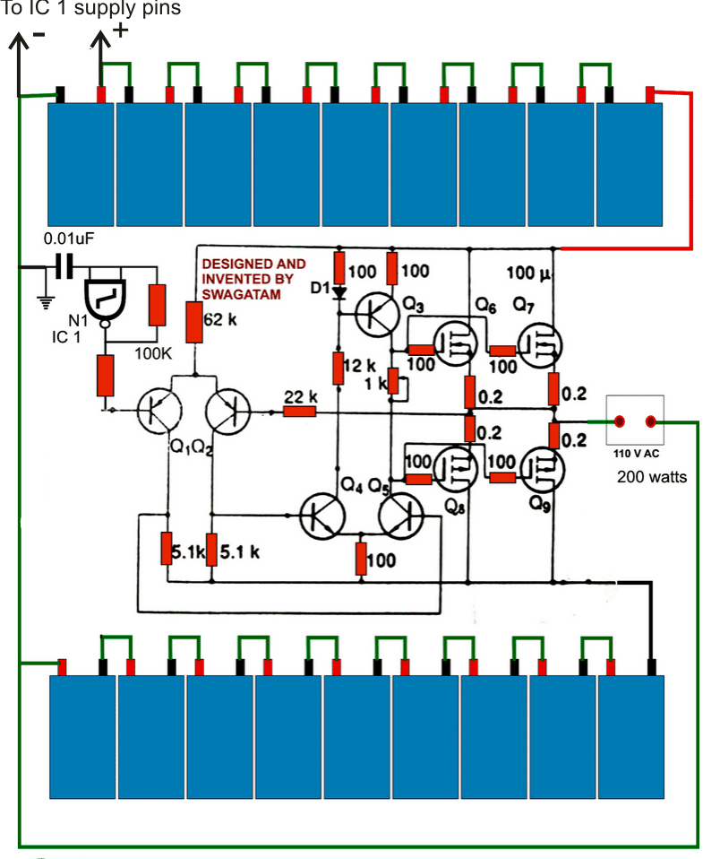
The standby current draw from my 2kva inverter is 0.68amps, please what will be likely standby current for 10kva inverter
As per calculation it should be 5 times more, around 3 amps
Hello sir, please what are the factors affecting inverter standby current draw
It will depend on the inverter design, some may have automatic systems for switching ON the inverter only when a a load is connected, but normally It is supposed to be only the oscillator circuit, transformer primary and the relays if any!
Good day sir, is possible to build 3kva/120v Inverter. Any drawbacks
Do you mean 120V DC input or 120V AC output?? If its DC input then its’ great, higher voltage means better efficiency.
Please how can I make a voltage stepdown for a 120v/10kva inverter oscillator
Please provide more info!
For the back emf, why didn’t it affect the utility supply
utility supply do not work with circuits, they come from generators.
Thanks for the advice, which one is electronic section,
the oscillator section which creates the 50Hz.
hi sir swagatam, i want to built a project inverter using 555 and 4017 with a transformer of single 12v/220v rated 1000va, do you have any circuit what u call them full bridge or h bridge circuit. thanks
Hi TCWS, If you want to make a full bridge inverter then using a specialized driver IC is most recommended. Using IC 555 and 4017 you can only build a center tap based inverter, not a full bridge.
You can read this article:
https://www.homemade-circuits.com/simplest-full-bridge-inverter-circuit/
thank you sir, may i ask? how about the article you post about the SG3525A with a full bridge power schematics? i have read it. is it possible to implement? or have no choice but to use the the recommended ICs. i have a EGS002 pure sine wave driver. thanks
Hi TCWS, I got the design from one of the forums, I have not tested it practically. Therefore I won’t recommend it to a newcomer. The full bridge drivers are foolproof and therefore there’s minimum risk in using them.
Good day sir, when I put my fan(50w) to speed 1 and 2, it works fine with inverter(2.5kva), but at speed 3 the inverter blew. But speed 3 is working fine with public utility, please what could be wrong
Love, what is blowing in your inverter, is it the mosfets and the ICs? Then it could be due to high amount of back emf generated by the fan.
add some capacitors 3uF/400V or similar across the output winding of the transformer.
see video in this link: https://www.homemade-circuits.com/1500-watt-pwm-sinewave-inverter-circuit/
Connect the electronic circuit section through a 100ohm resistor, and add a 1000uF capacitor after this resistor with ground. Add protection diodes across mosfet drain/source….add 1K resistor across gate source of the mosfets
Is it 1000uf or 100, as seen in video, please how does this function to prevent back emf
That’s a filter capacitor 2200uF for filtering interference and spikes not for back emf.
Thanks, please is it the MOSFET diode protection handle the back emf.
Yes it will!
https://electronics.stackexchange.com/questions/233394/how-can-i-protect-my-mosfet
Please which diode, type and value, can I use in the third diagram in this link, for drain-source and gate-source.
You can use a 12V 1 watt zener diode for the gate
Thanks, what of the drain
Drain already has an internal diode, still for extra safety you can put one 1N5408 externally
The max amp for in5408 diode is 3amps, can it handle high current.
which circuit are you referring to?
Hi Swagatam,
Longtime friend,
This article is well presented, though I have different but related request, I want to build an inverter using the same chip sg3525 but I’m using ferrite core instead of iron core, using basic circuits I manage to get 210ac at 30kHz, how can I use another Sg3525 to get 220ac at 50Hz!?
Preferably with automatic output voltage regulations.
My regards to you all.
Greetings from Tanzania ????????
Thank you Raymond, using another SG3525 might not work, you will need a full bridge driver circuit for this as shown in the first diagram from this article:
https://www.homemade-circuits.com/2017/10/5kva-transformerless-inverter-circuit.html
Good day Sir, please what’s the function of lower bc547 transistors
It’s for chopping the mosfet gate frequency into smaller blocks, so that the RMS waveform of the output can be set appropriately
I checked the THD of the inverter design using analyser, I got 8.8% as compared with 2.5% of the utility. Can I call it pure sine wave or what.
what kind of waveform are you getting?? If you can optimize a correct waveform and make it close to the utility waveform then the THD will also improve. You can do it by adding LC filters at the output
Thanks sir, please what is the relevance of the THD 8.8%. I have used LC filter.
Love, you will have to confirm the waveform first. If you are able to get a clean sine wave then the THD will be minimum. By the way it may not be fair to compare a homemade inverter with utility power, homemade inverter will always have a relatively higher level of THD.
Can we compare factory-made inverter with utility power supply
yes to a great extent!
Sir i got a 200w inverter wich usins sg3524 i modified it by hooking up the feedback for rms correction. The problem is when i connect a 16w led the output voltage drops from 220 to 212 if i increase load it keeps droping. Without load if i increase input voltage the output is not increasing meaning its only working on overvoltage not on undervoltage. Does this ic feedback work on voltage drop or am missing somethng. I know schematic is worth posting but dont have it.
Hi Francis, what is the Ah rating of the battery? Please check with ammeter the current consumption of the system by connecting in it series with the battery positive, also check whether the battery voltage is dropping or not. If the battery voltage is dropping will indicate that your system is drawing over current, or your battery is not good, and this may be causing the output to drop.
Feedback will not work for over load or over current situation if it exceeds the transformer or battery limits.
Hello Sir, please I have an issue with my inverter automatic voltage regulator made 7 months ago using an optocoupler. The issue is that for a week now it’s not regulating well any longer, I have to reset it manually, it may work fine for two days then I reset it again. I have tried replacing it but same result. Thanks .
Blessing, which schematic have you used? please show me the circuit diagram or the article link.
good day sir. I have problem with my SG3525A inverter feedback. my feedback is from the output of the transformer, through 280k resistor, through a diode, through one leg of 50k VR to pin 1. before I connect the feedback, the output voltage was 220v. but after I connect the feedback, the output voltage reading comes down to 0v with the inverter making a tickle tickle sound( though not loud). I tried adjusting the VR but the voltage does not respond. Pls help because I need this output voltage stabilizer seriously.
Abbey which feedback connections are you referring to? Is it from the first circuit, at pin#2?
Hello, I used a transformer of 12-0-12v rating to design an inverter using your 555 pwm model with Sg3524 ic, I thought I would get above 300v output at the transformer but I got 220v. Is it normal.
Please check the DC voltage at the gate of the mosfet, your transformer must be rated at this voltage to get 310V out. And preferably this DC level must be be equal to battery voltage divided by 1.41.
good day sir. thanks for your previous response. sir, can I use sg3525 square wave inverter to power a freezer. will it have any bad effect on the freezer? thanks.
Good day Abbey, it may work but may cause noise, therefore modified sinewave or pure sinewave is recommended.
thanks for all your reply . I think I am learning. sir, I used a 5000w stabilizer transformer to build sg3525A inverter using 6 irf260 in all. how can I know the power of my inverter. I only have digital and analog multimeter. can the output be up to 1500w?
Abbey, if it is a 5000 watt then you must get 5000 watts from it, you can check it practically by connecting appropriately rated loads to the inverter and check whether voltage drops or not, the load should work without dropping the voltage by much
sir, I don’t understand your last statement” MAKE SURE YOUR TRANSFORMER ALSO IS RATED AT THIS 50% LESS RATING AT THE PRIMARY SIDE”. Pls can you explain better? thanks.
Abbey, if your battery is 12V, the mentioned DC at the output pins should be around 6V, so the transformer should be a 6-0-6V
The correct value should be 12 / 1.41 = 9 approximately. So adjust the PWM to get 9V across the output pins of the IC, and select a transformer with 9-0-9V rating at the primary side.
thanks sir. Pls I will I know I have adjusted the PWM pot to modify sine wave since I don’t have an oscilloscope?
you can the check average DC voltage on the output pins of SG3525 while adjusting the pwm until it is almost 50% of the supply voltage, this will hopefully fix the most favorable modified waveform for your circuit…make sure your transformer also is rated at this 50% less rating at the primary side.
good day sir. thanks for all your post. Pls is the first circuit square wave or modified sine wave? if the last design uses sg3525 and it is square, what make the first circuit to be modify sine wave. is sg355A the same to sg3525?
adjust the PWM pot appropriately to make it a modified sinewave.
well done sir. Pls is the output from design1 modify sine wave or square wave. I am somehow confuse. since the last design using SG325 is said to be square wave I think the first design also suppose to be square. what make the difference. is SG3525A the same with SG535. thanks.
Thanks Abbey, for a modified version you must have the PWMs adjusted such that each block is followed by a gap or a “dead time” meaning it should be one square block then a “null” then the next square block and again another null and so on. This waveform when dumped into transformer winding will try to implement a sine wave like waveform.
In any SG3525 when you adjust the PWM feature to do the above then it becomes a modified sinewave. So it just depends how you are adjusting this PWM structure through the given pot.
If this pot is adjusted to produce full square waves then it is no longer a modified sinewave rather a simple square wave.
Hello sir, I actually built the above inverter circuit using ic sg3524 and 555 timer as the sine wave generator. I feed the 555 timer stage with 5v beside 8v fed to the ic sg3524. However, the pwm from ic sg3524 is being blocked by the collectors of the bc547 transistors at the bases of the power stage transistors. The question must sg3524 and 555 timer ICs have the same voltage feed or could there be something else?
Chinomso, the lower two BC547 are wired to chop the mosfet gate 50Hz pulses into smaller sections as per the PWM rate, …..it won’t block anything.
IC 555 can work comfortably with all voltages between 5V and 15V, so no problem with 5V…still you can use 8V for the IC 555 also to clear all doubts
Hi Swag, I have question on the 2 pure sine inverters I made. First, a 2kva/24v with trafo using 12swg in the primary side and 18swg on secondary with adequate filter capacitor 5uf, it carries my freezer easily even at 5% battery level
However, I made a 3.5kva/36v with trafo using 12.5 swg primary and 16swg secondary even with 32uf filter capacitor it could not carry same freezer at 40% battery level but carries it at 75% or more battery level.
Sir,what could be responsibl for this low power bigger trafo pure sine inverter(according to your design)that could not carry much load. Thanks Chief.
Love, did you calculate the parameters perfectly while designing the transformers? If you do it by trial and error then that won’t allow you to understand anything regarding its working principle. By the way 12 and 18 SWG ratio does not look OK, neither does does 12.5 and 16 SWG ratio. The secondary side should have proportionately much thinner wire than the primary side.
Please do it with proper calculation and if possible take the help of a professional transformer designer.
Hi Swagtagam, please what is the effect of using high value filter like 32uf in this inverter
Hi Love, if you are referring to the transformer output capacitor, 32uF would waste a significant amount of power, not recommended.
Thank you for the update, please for 10kva/120v input, what are the modifications.
upgrade mosfet and transformer rating accordingly.
How can I step down the voltage input into the oscillator, and for 120v input which MOSFET can I use. Will irfp 260 do
you can use 7812 IC for stepping down…..please check the datasheet of the mosfet and make sure the Vds and Id specs are as per the required specs.
Please how can I add a power saving mode to this design to conserve energy. Thanks so much Swag.
You can add this to your inverter:
https://www.homemade-circuits.com/2015/07/no-load-detector-and-cut-off-circuit.html
Hello enginner , Secondly we all understand that technologies have reached its peak, such that it is like morden inovations principles are trying to disagree with early lay down principles upon which many have built their knowledge. Please my questions. I have seen from a blogger from Indonensia who display a pure sine power inverter with frequencies, one is after building gives 77hz ,second 32 hz.Which from his videos he used induction machines like electric driller, fridge,water pump,set up table computer and eletric stove. I am not quiet at ease with it. I know please globally two grid frequencies 50 & 60hzs please your advice.
Ekoe, the frequency of a pwm based inverter must be measured and confirmed using an oscilloscope, a multi-meter can give misleading results.
Please swag.I need a pure sine wave inverter circuit that uses two ir2110 for high/low drive to the transformer.It may use any oscillator.
Hi Joseph, you can refer to the second circuit on this link:
https://www.homemade-circuits.com/simplest-full-bridge-inverter-circuit/
For sine wave you have to integrate SPWM at the low side MOSFETs
Hi Swagatam, I want you once again that you trow more light on the concepts of choosing transformer and power transistor to a paticulation power inverter oscilation circuit to obtain a desired power. Please consider me, am still not getting hold on this fundamental principles.
Hi Ekoe, there’s nothing complicated in it, just divide the maximum intended load wattage with the battery voltage and get the amp value, then make sure the transformer’s and mosfet’s V and I rating are higher than these acquired value
Hi sir, I use copper wire for my MOSFET cascade but when the MOSFETs got burnt due to any reason, and I replace the MOSFETs with same quoted Copper with the black soot from the burnt MOSFETs , the MOSFETs blow again until I change the copper wire. Then no more MOSFETs burning and the inverter is working fine.
OK, thanks for updating the issue!
Hi sir, sorry I was trying to ask why the MOSFET blowing incident. Thanks
Tinuke, mosfets are complex devices, and there can be many reasons for their malfunctioning, you can read the details here
https://www.homemade-circuits.com/mosfet-protection-basics-explained-is/
Thanks Sir, please why is my built inverter gets voltage stable at 220v, 61hz, what could be factors for the 61hz frequency and how can I make it 50hz.
Hi Tinuke, please measure the frequency across the output pins of the IC, do this by disconnecting the mosfets from the IC, confirm whether it is 50Hz or not….
I checked, it was 61hz but when the frequency pot was adjusted it got to 50hz.
then keep the pot adjusted to 50Hz and check again
Thanks it is better after several tweaking I now got 52hz, please what is the size of Ac output capacitor can I use for 5kva/48v because the combination you gave from the redirected page, is not efficient.
I am glad you could get the right frequency tinuke, however I am sorry, I do not have any other calculations other than what I suggested you in the referred page.
Well done Swagtagam, please how can I set the spwm or pwm (comparing circuits ) preset correctly to get pure sine wave without an oscilloscope because I turned the preset to Max and min without obvious difference.
Tinuke, there’s no way to confirm a sine waveform without using an oscilloscope, but to some extent it can be verified through a multimeter by checking the output of the transformer. If the voltage varies in response to PWM variations that would confirm that the PWM function is working.
Thanks, I checked the spwm output, it varies as I turned the preset, does that mean it is working.
The 220V output from the transformer must change in response to the PWM variation.
Thanks sir, the trafo output is changing with pwm variation, please how can i avoid spurious sine wave.
sorry I could not understand what you mean by “spurious sinewave”
Thanks for your response, I have sorted out the wave. It’s working great. Between modified and pure sine wave I made using your circuits, the two inverters carried the freezer, but the pure sine worked smoother but the two required thesame output filter.
I thought pure wave inverter will require lesser filtering to carry the freezer. Please educate me
Great, I am glad you could sort it out, the filter capacitor or inductor values can be experimented manually…. but only with the help of a oscilloscope
Hello sir, I checked the waveform using goldwave software for the waveform looked the same for the three-modified inverter, pure sine wave inverter I built at 50hz and the public utility power supply. They all produced sine wave. But at extreme of the preset value for pwm of pure inverter and at 51hz upward for the modified inverter, the waveform was poor.
I want to ask why did the modified inverter produced same good sine wave as the pure inverter and the utility. Thanks for your enlightenment.
Tinuke, the Goldwave software is actually designed for analyzing music frequencies, I am not sure whether it will be able to check an inverter frequency, because when I tried to check square wave from an inverter using this software it simply did not work.
Can you please specify which two inverter designs are you comparing? Is it from this website??
A sg3524 circuit but upgraded it to the pure sine wave using your pwm bjt stage.any suggestion please
OK, but you will have to use a real oscilloscope to test the waveform, a PC based software might not give correct results. You can try the following concepts for making an osciloscope at home for the purpose
https://www.homemade-circuits.com/?s=oscilloscope
Thanks Swag, i got an oscilloscope, the waveforms are different for the utility, pure and modified sine inverter. I tried tweaking the filter output and the pwm preset but the pure sine inverter I made using your bjt/ pwm stage didn’t come out as perfect as the utility power supply. Although the waveform was better than the modified inverter. Please how can I improve this. Thanks.
Hi Tinuke, what kind of SPWM are you seeing in the oscilloscope? How many blocks are there on each waveform and in what order? Please clarify these I may try to help!
There are combination of sine and sawtooth waveform( occasionally), 2 blocks in a waveform. There are different waveform with different load. Thanks so much sir.
Please check on the DC side, and make sure the blocks are in the SPWM format, that is widest block at the center and gradually narrowing blocks on either sides.
Total number of blocks should not be more than 7
Thanks Swag, there are four blocks with the second, the widest. Any advice please.
Tinuke, it number of blocks should an odd number, like 3, 5 or 7, and the widest block should be at the center, so please make sure the SPWM is configured correctly.
It is three blocks, the widest block the first. Thanks for the correction.
the widest block should be at the center! and preferably there should be 5 blocks as shown in the IC 741 output in the above article
Please how can I make it 5 blocks, any modifications sir
the fast triangle waves must be 5 times more than the slow triangle waves.
Good day sir, from the spectrograph of this pure sine inverter I built, there are so many harmonics as compared with the bought pure sine inverter an the utility supply, please how can I reduce the harmonics, I have used different filters. Thanks Swagtagam.
Hi Tinuke, Can you show me the image of the spectrograph? I’ll try to analyze the reason. Upload it to any free image hosting site, and provide the link here.
By the way you must use an oscilloscope for analyzing the waveform, i am not sure how a spectrograph can work for analyzing inverter waveform.
Good day swag, Can this circuit be modify to single transformer inverter, what are the components in modification? thanks
yes it can be perhaps done, by modifying the transformer, mosfet stages in the same way as implemented in one of the relevant designs in this website.
I made this circuits working perfectly 1.5kva/24v, with LC filter but when I load my washing machine at few times the output frequency which was set at 50hz jumped to 2.2khz,16khz…. For 1second To return to 50hz, why this, what can I do, I added more filters no difference. Thanks
I am glad you could make it successfully, however the issue which you have mentioned can be difficult diagnose without a practical check, it could be perhaps happening due to instantaneous harmonics generated by the transformer winding or by the load motor winding…you can try installing MOVs at different nodes of the circuit and check if that solves the issue
Yet to get resolved, any other advice Sir.
Which filter system is good for inverter output. RC or LC system
LC is more effective as far as I know…
and sir can i use bc546/ bc547 because i could not find bc556/bc557 thanks
one should be NPN and the other PNP….BC546 is not a PNP, so please make sure to replace it with a pnp
by the way the shown pair is not BC556/BC547…rather they are BC547/BC557…
sir can pin 4 of sg3525 generate slow triangular wave form as you mentioned in one of your post
the Ct pin (pin#5) is supposed to generate it…please confirm it with a scope first
thanks sir for your quick reply
one more thing sir to creat the SPWM device that mean instead of using two ic556 to creat slow and fast triangular wave form i can just make use of only one ic555 and ic741 while i tap a slow trianguler wave form from the sg3525 to generate SPWM for the inverter
yes that’s possible, but just check and confirm whether the triangle wave from the SG3525 has a peak equal to the 555 triangle peak or not…they should be approximately equal for optimal results
sir i was reading through some of your comment to ( mr faith) of how to generate SPWM under this thread you said that one can extract triangular wave form from pin 4 of sg3525 for slow triangular wave form
and pin 6 and 2 of any ic 555 wired as a astable circiut for fast triangular wave form
sir my question is that the diagram of ic555 being provided by you sir has a resistor port for adjusting the PWM output
sir my guess is that as we adjust the port we increase or decrease the voltage at the transformer output or will we have to modified the ic555 circuit
my last question is sir are we going to make use of the PWM being generated by the ic555 thanks sir
Abioye,
As per my assumptions, adjusting the PWM to extreme levels may cause abnormal SPWM behavior, because too narrow or too wide PWMs may force the triangle waves to become discontinuous or without significant valleys between the triangle waves which can cause inefficient SPWMs. But yes it can be applied for controlling the output RMS voltage of the inveter. The ideal PWM should be to a 50% ON/OFF cycle for initiating a reasonably uniform triangle waves…all these will to be verified with practical trial and error method…
Please, how can I make the inverter frequency stable at 50hz as against 55hz I presently get. I desire it to be 50z. Thanks
use a voltage regulator for the IC, such as a 7812 IC
Thanks sir, I put 7812. But still 55hz. Is it possible for a pure sine wave inverter to have a frequency of 55hz
measure it across the IC output pins with a good frequency meter….alternatively you can feed the IC SG3525 externally using a separate oscillator IC circuit such as IC 555
55Hz may not be appropriate for any appliances
Please any circuit for the combination of sg3525 and 555 for better frequency output.
Hello, my inverter is faulty affect some months of usage, I discovered two bjt transistor were bad, why sudden damage, although the output to drive the MOSFETs is a bit different, 7.02v and 6.90v could this be a reason
which schematic are you referring you to?
The bjt/pwm stage in this page, the bc547/bc557
keep the fast frequency of the SPWM to 350Hz, not more than this. try adding a 1K resistor across gate/source of each mosfet
Hi swagatam , my friend bought a standard purewave inverter, but about 6months the crt TV got burnt why the led TV is still working. I found the parameters are still 228v output voltage, frequency 50.12hz, what could make the TV got burnt.
Dayo, LED/LCD TVs normally incorporate a stabilized SMPS for powering the circuitry…therefore these are well protected internally and can survive upto 300V, and that may be reason why the LED TV is not yet affected, while the CRT which was not so well equipped burned due to a possible switch ON surge…
Good day sir, I built this inverter, but within hours of use with my CRT TV, the TV color behaves funny in that the pictures go so dark that I barely see the image then later come out so nice. Please what could be wrong sir, help out. Thanks
Dayo, that could be due to a loose connection, a bad solder, or a low battery…..please use a good PCB for making the inverter circuit and check the response again…also make sure the output from the inverter is below 250V
Please how does low battery affect it, because my battery is presently bad. Thanks.
CRT TVs will generally blackout under low voltage conditions, below 170V. Try an LCD or LED TV, they will work without problems, until ofcourse the voltage drops too low!
OK sir, my TV input voltage is 110-240v, please could there be any other reason.
OK sir, but the old modified sine inverter I used for years didn’t have this issue but I wanted to try to upgrade to pure sine wave using a 555 ic and an opamp ic with your bjt stage.
Even now when I uae the modified inverter it now have the same issue. Please help .
It will be difficult to understand because I don’t know anything about the modified inverter circuit and its specification. The best thing would be to monitor the waveform and voltage during the testing period…
I know how to generate my spwm what am asking is that i will be needing a second opamp for my feedback and again
Please can you give a range which the frequency of the filter will fall or can it be the same frequency as the spwm
sorry, I have no idea regarding the filter frequency…you will have to calculate it with thorough experimentation.
Ok that is i will be needing a second opamp, and again Please can you give a range which the frequency will fall or can it be the same frequency as the spwm. Lastly can i use the circuit for hbridge
for the triangle slow wave you can extract it by processing the output from pin#4 of SG3525.
the fast triangle waves can be achieved from pin#6/2 of any standard IC 555 astable circuit
you can use the SPWM circuit for H-bridge also
Good day Mr swag., i want to thank you first for your good work, but i have few question to ask
1. If i use spwm to modulate the signal i.e instead of using pwm i now use spwm how do i set my feedback considering that i will generate my spwm using two 555timer and one comparator.
2. What will be the frequency of my output filter is it a high frequency filter or a low frequency filter
feedback can be achieved through an opamp comparator stage by configuring it with a resistive divider stage across the inverter output, and the output of the opamp fed to pin#1 of IC 3525. The resistive network should be adjusted such that whenever the output tends to go higher than the normal level, the oamp output turns high narrowing the PWM content
the output should have a high frequency cut off filter
Good day My Tutor,
Is it possible to use a none centre tap transformer in any inverter circuit using already a center tap transformer? If real , what modification can be done?
Ekoe, that can be possible only if the oscillator section replaced with a full bridge IC stage, please type full bridge in the search box, you will be able to find a few concepts using this topology.
Hello Swag, When you are building any Power inverter circuit , and you want to match with a transformer to obtain a maximum loading power for example a center tap, is it the voltage that you have from the output A& B of the circuit as a driver voltage let’s say from 3-9volts to the power transistors , on that you base your transformer input voltage say 7 -12volts?
You have to consider the average voltage which is coming to the gate or base of the power devices from the IC, and then make sure that the current of the trafo is selected as per the load wattage with respect to this voltage, that is if the required load wattage is 200 watt, and the average voltage from the IC to the mosfet gate is 6V, then the trafo must be rated at 6-0-6V and 200/6 = 33 amps for primary…and for secondary this will be proportionately = 200/220 = 0.9 amps.
Hello Engineer,
Please educate me on this very issues and ease my mind. My question is odd, and is this, Any time I am browsing through the internet and I see any educative article either in video or not, films and music. You will always see subscribe, now if I go ahead dowloadind Am I doing harm in cheating on the publisher of these articles? Or the money deducted from my internet bundle after is shared indirectly to the owner of the website. Please what is the right procedure, endure with me thanks .Because I want to correct my mistakes.
Hello Ekoe, subscribing and downloading is not wrong for the publisher, but frequent downloading will increase your internet bill for sure
I made sg3525 inverter but one ouput of sg3525 is higher than the other output about 1 volt
Is my ic fualty
1V difference may not be a problem, but is it oscillating? confirm this with a frequency meter or with a headphone…
How to check oscillations with headphones?
connect the headphone leads with the output of the IC, vary the frequency pot of the IC, and tweak it until you find an audible note on the headphone…this will confirm that the IC is oscillating and is working OK
Can i use sg3524 instead of sg3525
yes you can
Thanks Mr Swagatam for the quick response to my question on my modified inverter more grease to your elbows.
You are welcome!
Hello Mr Swagatam happy new year,
My tutor, am building a modified inverter with sg3524 circuit. I used 1400VA transformer from an old UPS, When I put power into the inverter the battery negative terminal get what quickly within 1 minute as if the cross section of the cable is small. Also the power transistors run very hot which cannot last for an hour .The primary input of the transformer reads 9volts a center tap, and it sounds heavily when powered. Am confused engineer, resolve my problem please thanks.
Happy New Year to you Ekoe,
This can happen either due to a mismatch between between battery voltage and the transformer voltage rating, an unbalanced trafo winding or a faulty IC which may be generating incorrect oscillations or frequency. please check all this parameters using an oscilloscope or other suitable test equipment and make sure these are perfectly implemented
Many thanks to you. Sir I have a problem on the buffer stage, am getting 4-5 volts on mosfets gates instead of 12v why? I have changed all the transistor still the same, I also tried other transistors(c1815 and a673) on another pcb no change. But when I isolated base of the bc557s the voltages rose to nearly12v. Where am I lost?
50% less reading is fine, and is due to 50% duty cycle of the SG3525 oscillator wich is causing the meter to simulate the average 50% value of the supply level, you can confirm the same on the output pins of the iC directly…if the readings match then you can assume this to be perfectly normal.
removing 557 removes the negative cycles from the reading, causing the meter to show only the ON time, so may be this is causing the 12V to appear on the meter
Thanks once again for that. If that is normal as you said then will that be good enough to drive 20NM50 on h-bridge without causing them to overheat?
What you are seeing on the meter is the average value of the voltage but the peak value is always 12V (or the supply level), meaning the ON time of the frequency is always producing 12V, therefore any connected mosfets will have no problems conducting optimally
Thanks once again. I have introduced the 555 circuit to my inverter but now the lower two bc547s are shorting the oscillations completed ie from 5.6v down to 0v. I measured the output of 555 is 11.5v but I not sure if that is PWM because I don’t have oscilloscope.
I tried to built another circuit using other components of same marks but still.
your PWM IC 555’s output at pin#3 should vary from 5% to 95% of the supply voltage that’s applied at pin#4/8 of this IC in response to the PWM pot rotations.
If this is not happening then your PWM circuit might not be working or could be having some fault…please confirm this…
Ok I see so what is the best position of potentiometer to achieve a fair waveform I have set it at the middle inverter working fine but I don’t know how the waveform is like because I don’t have the oscilloscope?
the waveform will be quiet similar to what is shown in the following article
https://www.homemade-circuits.com/modified-sine-wave-inverter-circuit-2/
set the PWM which allows the gate voltage of the mosfet to be at a level equal to the transformers winding rating…if the winding is 6-0-6, then make sure it is 6V, or if the trafo rating is 7.5–07.5 then adjust it to 7.5V approx these would be with reference to a 12V battery.
hello sir
i salute the great job you are doing, where else can we find free tutorials like these?
i think you have been sent by the heavens……
i constructed the above circuit which was drawn by Ainsworth Lynch, the 3525 did not output signal from pin 11 and 14 though it was warm meaning there was power. i looked again into the schematic and compared to the one you drew and found that pin 9 was directly connected to the ground instead to the R1 which then link pin1. after that correction there was output.
although i am a new born to electronics ,I’m a hobbyist of electronics wiling to know better.
My question is ……. whats the prpose of 555 and lower two transistors ,can that not short pulses from 3525 to ground?
Hello Francis,
I am glad you liked my site.
Yes it seems the drawing created by Ainsworth has a mistake, no problem readers can correct it by following the other diagram, and anyway this article is not about the SG3525 circuit, it’s primarily regarding understanding the technique of converting any square wave inverter into a sinewave.
The IC 555 or the SWPM feed will short the waveform, but it will do it in steps which will ultimately take the shape of a sinewave at the output of the inverter therefore chopping or shorting of the actual square waveform into stepped waveform is deliberately introduced in order to acquire the intended sinewave output.
If you have any further questions regarding any of the concepts presented in this website, you can feel free to inquire, and get them solved from me.
Ok I now understand the use of 555 in that circuit.one more question, how is the pwm from 555 ic incorperated to short part of the waveform at the right time to reshape square wave into stepped waveform? Is it because the two ic start at the same time or ? What if I introduce the the pwm from 555 later in the operation of 3525 ? In other word how does the two ic sync?
The bottom concept does not require synchronization because it is not generating an SPWM, it is only chopping the square wave into uniform pieces therefore it does not have to be in sync with anything, however if an SPWM is employed where the each waveform needs to be carved with precise sets of PWMs then syncing may be required.
You can see how the procedure is implemented in the following example
https://www.homemade-circuits.com/5kva-transformerless-inverter-circuit/
sir swag…can you give me the part list of this pure sine wave inverter using sg3525 because other component is not clear…plss sir…
Hi Denmark,
please do one thing, just copy down all the part numbers that you are able to see in the circuit diagram, and send it here, I’ll check it and verify it for you…. and if required add more info in it.
Good day sir, please what can I do to frequency drift of my inverter in response to variation to battery level and load. Thanks
operate the oscillator stage through a 7805 or 7809 IC regulator…
I used 7812, is it bad . Thanks
is it controlling the supply to the IC at 12V constant, throughout??
Yes, the supply is constant.
with constant supply, frequency cannot vary for any IC, better check the voltage or the frequency again carefully
I used 100uf capacitor with 7812 regulator, it supplies constant voltage initially but as battery level changes the frequency drifts
try 7809 IC
Sir, I have 7805, can I use it.
How can i set the frequency of the circuit, or to calculate it?
please check its datasheet for all the details..
Pls sir i need your help, so now fo this present circuit what is the frequency?
Solomon, frequency should be set to 50Hz, and you can check this across the output pins of the SG3525 using a frequency meter
Hello swagatam, thank u very much for helping alot in construction of this wonder inverter circuit, what i need now is to help me design a pwm generator circuit using op amp for pure sine wave output. Thanks
You are welcome solomon, the PWM generator is already explained in the article….if you want to replace the IC 556 with opamp then you will have to use a opamp based triangle wave generator such as this one
" rel="ugc">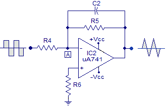
you will need two of these, with different frequency setting to get the required fast and slow triangle waves.
The square wave input can be fed from a IC 555 circuit.
Thanks. Sir, is there need for delay timer for an inverter?
that depends on the user preference, it is not necessary.
Hello sir, i have to questions to ask:
1. what is the minimum AH battery can each of the inverter can handle: 5000w, 2000w, 1000w?
2. What is the maximum current for charging each of the battery: 100AH, 50AH, 12AH?
Hello Solomon,
the circuit can handle any battery with any rating as desired by the user.
The mosfets and the trafo ratings will need to be matched with the battery rating appropriately.
It is ideally 1/10th of the AH rating, divide the AH with 10…..
Thank u sir, But is any problem if i connect the four MOSFETS together on 500w transformer and use 50AH Battery?
If two mosfets can handle the power then adding extra two will be a waste, it’s your wish, you can add them if you want.
You can use a 50 AH battery for a 500w trafo , there are no restrictions as such…
Thank u very much sir. Pls more questions sir. I raised an argument with my friend about N channel power MOSFETs, there are some of the MOSFETs that has a diode symbol on their body, he said that those that have the diode symbol on them are local quality product and get hot easily or even burst during operation while those that doesnt have the symbol are good and original quality, and i oppose that. Pls help me with the correct answer.
Second question: in the second circuit containing SG3525 Ic, which type of capacitor can i use for the non polarized, is it ceramic or polypropylen type or both. help me and clear my doubt. Thanks
Hi Solomon, your friend is wrong, and he doesn’t make sense. All modern mosfets today have an internal diode for back EMF protection, and it is an enhanced property designed within all modern mosfets.
For the capacitors you can use any good quality 50V rated non-polar capacitors, even ceramic discs will work as fine….
Well done sir, i salute you. Thanks alot, one more question: what will be my waveform output if i use 555 timer for pwm
You are welcome Solomon, the output waveform will be just as shown in the following article
https://www.homemade-circuits.com/modified-sine-wave-inverter-circuit-2/
Thanks, Sir, if i use Four MOSFETs(two-two each side of the winding) can it handle 5kva transformer? Because i want to use IRF1404, which power of transformer can it handle 1000w, 2000w
Yes definitely it will be able to take 5kva, but make sure to mount them on large heatsinks…
if the power output is 5kva then naturally the trafo has to be a 5kva or around 5000 watts
sir pls dnt be tired with me, i wanted to gather all my questions to post, but i forgot, before i still forget, i have more questions:
1. in choosing or selecting the MOSFETs, what must i consider, is it the volt or the amp?
2. For knowing sake, i there any diferences or similarities between an inverter transformer and a stabiler.
transformer in terms of winding?
3. Can i use a stabiler transfor(5kva stabilizer transformer) to connect my inverter circuit with?
4. What is the relationship between MOSFETs and transformer in terms of power capacity. Pls help, thanks.
Hi solomon, here are the answers:
1) you must primarily check the Drain-Source voltage and the continuous Drain current ratings for mosfets
2) All transformers work with the same principles so there’s no difference as far as functioning is concerned, only the V and I ratings may be different…
3) You can if the winding specs are compatible…
4) mosfets are just switches, therefore their current and voltage rating must be adequately rated to handle the trafo wattage…preferably the rating of the mosfet should be at least 1.5 times higher than the trafo max wattage.
Hello sir, thanks for the circuit, i appreciate and so grateful. I have something to ask whether it can work, can i configure those MOSFETS in pairs? (meaning each side two-two)
Thanks Solomon, yes definitely you can add more mosfets in parallel for upgrading the capacity of the design….
Ok, thank u sir. Sir, when connecting them parallel must i connect a resistors in series with their or just direct parallel connection, if with resistor what values
yes all the mosfets must have their own gate resistors, any value between 10 and 100 ohm will work
Good day sir, I made a 36v inverter but I have issues with the duty cycle, without load is 60% but with load 50%. I have tried LC filter but no avail, please assist.
Tolu, duty cycle should be 50%, so it is not an issue…you must check the voltage at the output…..
Good day sir, voltage is varied from 190-250v but still between 58-60%
Duty cycle is between 58-60%
how are you measuring the duty cycle??
I use my multimeter
how can you check duty cycle with multimeter?? how will you know what is the exact ON time and OFF time through a DMM??
hello sir.. thanks for updating our ideas on electronic.. please sir I need an Automatic change over circuit that will automatically switch over my inverter to power source in my room when light is been restore.. thanks
chucks, such designs are already present in my website, please check the relay changeover category
thank you for your good works!, can I use it for my sg3524 circuit
thanks, yes you can use it…
Hello sir, pls i have few questions to ask:
1. I want to add power transistors (2N3055) to this circuit when completed with the SG3525 circuit, and i want to use the arrengement and the pin connection like the circuit of 200VA square wave inverter u posted, i want to increase the wattage of the circuit using the transistor, pls help me to configure the pin connections where to connect them.
2. Can i use the AC mains output of the inverter circuit to a 12v battery charger to charge the battery of the inverter itself? Is there any effect to the battery or to the inverter? Pls help me sir. Thanks
solomon,
you can replicate the arrangement which is shown in the following design, and use it directly with SG3525 circuit
https://www.homemade-circuits.com/48-v-inverter-circuit/
your second point cannot be feasible…
ok, thank u sir, so now what will be the maximum power of the circuit
Maximum power will solely depend on the wattage of the trafo and the battery AH rating…
Thanks sir, I made a pure sine wave inverter 1Kva , buy goes off after 40mins which I will need to switch on again, mosfets are cool. I troubleshoot , couldn’t get the fault. Please, what can I do . Well done sir.
Love, which circuit did you make? without seeing the schematic or the block diagram it can be difficult for me to judge the fault??
sir can you suggest what is best in our thesis project….we want to build a power inverter for our school…in case of power outtage we have emergency electricity…we want to installed it in our electronics lab…plsss sir…we need a tested power inverter that can run the appliance at the same time …tnx sir…
Hi Denmark,
All inverter circuits are tested designs here, either by me or by the users, but all these circuits require an expert level knowledge to complete them successfully.
I can suggest you a simple one which you an try, here’s the link:
https://www.homemade-circuits.com/how-to-make-simple-200-va-homemade/
Please sir, if I want to do 48v inverter, will I feed 48v +dc battery in bjt stage or will I step down to 12v to feed into it. Thanks
Dayo, only the trafo center tap will connect with 48V source, rest everything must be isolated and connected with a 12V or 15V input
Sir good day, what is the value of transformer…
you can choose any value as per your required specifications and battery specifications
Sir can i ask if these project is tested…and can you give me the parts list of this project….sir i am a electronics student turning 4th year college and our thesis project is power inverter using dual motor…can you suggest sir if what inverter is the best for our project….that can run the appliance and bulb in case of power outtage or brown out in our school..we want to installed it in our electronics lab.. Thank you very much sir…godbless you
Hello sir, pls i have some question that u should help me answer in the first circuit:
1. What output waveform, it is modified sine wave or pure sine wave?
2. what is the function of the two MOSFETs at the 12v tap of the transformer
3. What does it mean by the resistor 10E
4. How can i attach/connect the pins of a power transistors(2n3055) to the circuit. Pls sir help me to answer them
Ansrwes:
1) If you use SPWM feed it will be pure sinewave.
2) the mosfets respond to the gate frequency and correspondingly switch the two transformer winding with high current. alternately.
3) 10E = 10 Ohm
4)You can connect them as indicated in the following article, using a Darlington pair:
https://www.homemade-circuits.com/48-v-inverter-circuit/
Thank u very much sir, in fact i appreciate, one more question pls, what is the function of the capacitor at the output transformer?
The capacitor is to smoothen the output waveform and make it more like a sinewave output
Sir, For the MOSFETs, can i use IRF540? or pls tell me a recommended MOSFET atleast two or three different types
yes IRF540 will work!
Hello sir, where is pwm output for this circuit
PWM is obtained from the IC 555 circuit or the opamp SPWM circuit.
Hello Mr Swaggart, Can a choice of a timing capacitor and resistance when calibrating an I.C for frequency let’s say 50hz.Would it influence the d.c & ac current or voltage at the outputs of the I.c circuit. Is it a factor? Please Doc.
Hello Ekoe, do you mean to say the duty cycle?? yes the duty cycle or the ON/OFF time of the 50Hz frequency can affect the output current and voltage….it should be set at 50% duty cycle to ensure a 100% current/voltage output
When I measured the the frequency was not stable ranging from 120hz-260hz. Can it still work
where did you measure the frequency? please provide proper details
When I measured the down the frequency was not stable ranging from 120hz-260hz. Can it still work
what is down frequency?
Hello, is possible to measure the frequency of spwm and set before connecting to be bjt stage.
yes, and that has to be done without fail…
Hello, I made two inverters one works at 150hz but the mosfet did not blow with an inductive load but blow at 50hz for the second inverter. Why, and what can I do
that will be difficult to judge, because mosfets can blow due a many different reasons, mostly due to parasitic inductance within the tracks, volatge spikes etc…
https://www.homemade-circuits.com/mosfet-protection-basics-explained-is/
Good day engineer, I made a 36v inverter(secondary trafo guage is 16swg)
but when used to power washing machine, the machine works heavily but when used with 12v inverter, the machine works smoothly.
Tinuke, it’s simply beause your 36W inverter is not correctly built and it is not delivering the required amount of current to the load….you can confirm by attaching an ammeter in series with the battery and check how much current it draws, and then multiply the result with the battery voltage…that will give you the output power range of the inverter
if you think everything is correct then where is the fault?? something has to be wrong somewhere…which you must find out
you cannot troubleshoot or build a circuit without understanding the stages or without proper equipment.
please do not make it blindly, check the stages with a meter with proper understanding, if your BC547 is ON continuously it means your 741 IC is not producing the PWMs.
you can use 3.3V also
did you understand why the zener is being used, no point in trying randomly…
yes it will do…
Please help me design a circuit for inverter voltage stabilization in reference to varying battery voltage and load variation. Thanks sir
I think I have already referred you the circuit in one of the previous comments, anyway you can check it out here
https://www.homemade-circuits.com/automatic-output-voltage-regulator/
the output will be regulated only as long as it is not an overloaded
Try adding a 4.7V zener diode at the output of the IC 741…may be the IC 741 is generating a leakage voltage which is causing permanent switch ON of the BC547
you must check waveform for this circuit, checking volts will not help…
please don’t do it unless you have without proper equipment and detailed understanding.
how would you check the output waveform and whether it is generating PWM or not?, please tell me how will you confirm this without a scope???
Hello sir, please between mosfet and igbt which one is better in efficiency and other features assuming they have same spec
It is IGBT which has better efficiency than mosfet, if the load current requirement is high
Hello engineer, what would happen if any power inverter built with 60hz frequency is used for electrical gadgets operating on 50hz frequency.
And if there would not be any trouble can this application be done the other way round ?
Hello Ekoe, except inductive loads or timer based loads, it wouldn’t have much effects on the load
hi
iam building an 1KVA inverter using isw20n90 mosfets. but i needed a closed loop pwm driver ic for my inverter
can you suggest me any IC which i can get it in market.
Hi, by closed loop do you mean an automatic load control through feedback? Please elaborate on this
Sorry the frequecy of switching is 20 KHz
Hi Sir,
I am designing a Bi directional Inverter for domestic application having a variable load, I should drive mosfets using a spwm IC which can support a closed loop purpose,
The output load limit is 600 W, the mosfet used are isw20n90, the switching frequency shall be greater than 200kHz, can you please suggest me an IC for this purpose
Thanks in advance
Hi Abhilash, by bidirectional do you mean to say a full bridge type?
Anyway, you can refer to the following design, which will perhaps fulfill your need:
https://www.homemade-circuits.com/5kva-transformerless-inverter-circuit/
Hi Swag,
I want to know if adding a pull-down resistor between the outputs of SG3525 (before connecting the gate resistor) will help the switching performance of the IC.
Hi Reoc, it is not mentioned anywhere in the datasheet of the IC, still there’s no harm in trying it.
Hello sir, please how can I minimize my modified wave inverter noise, everything working fine .thanks
tinuke, try placing an inductor and capacitor network across the output winding of the trafo…..you can take the help of the concept presented at the end of this article, in the magazine page snippets
https://www.homemade-circuits.com/how-to-make-simplest-inverter-circuit/
Swag,
Everything is working very fine now. At first, I used IRF250 as my power MOSFET (one for each arm of the switch).
When I tried using 100N25 (two for each arm of the switch), the MOSFETs burns out. I have repeated this and the MOSFETs kept burning.
Whenever I revert to using a single IRF250, the inverter works very fine.
Can you please advise me on what to do, thank you.
Hi Reoc, if one type of mosfets is working and the other not working then clearly the one which is not working could be a non-compatible type for the present application…or possibly those are faulty originally…
can you please tell me the voltage and current specifications of the bad mosfets from its datasheet, that will help us to confirm the tests.
Hi Swag,
From my observations, it seems like the burning MOSFETs were not clamped firmly to the heatsink. I believed this because any of the MOSFETs clamped firmly to another heatsink works very well.
I want to know if this can cause them to burn out.
Hi Reoc, that may be possible, however mosfets are positive-temperature-coefficient devices, and therefore will normally try to shut-down as its core temperature increases, so a loose clamping may result in poor efficiency, but not in the burning of the mosfets…there could be some other potential reason.
Hi Swag,
What can cause my MOSFETs to burn within 5 Seconds?
I am using a gate resistor of 22ohm and I connected a 10k resistor between the gate and the source. Please help me out, thank you.
Hi Reoc, if its blowing even after connecting everything correctly, then the possible cause could be the reverse spikes from the trafo winding…try installing rectifier diodes across the cathode/anode of each mosfets and see if that helps.
I discovered that there was a dry joint (not properly soldered) in one leg of the SG3525.
I have soldered it well but there is another problem, the 22ohm resistor connected to the gate burns out after a short time.
Please can you help me by suggesting a solution to this, thank you.
22 ohm is the gate resistor which should never burn because mosfet gates have a high impedance, it seems your mosfets are damaged or faulty originally.
Will the circuit work if the duty cycle of the secondary PWM is 50%?
which secondary PWM?
I mean the PWM of 400Hz, I was asking if the system will work when the duty cycle is 50%.
it can be 50% or any other value depending on your transformer specs, you can tweak the duty cycle to adjust the RMS and also the output wattage.
Hi Swag, I think when the frequency of the second PWM is 200Hz, it will only chop the primary wave into two. For you to chop it into four, the frequency of the second PWM must be 400Hz. I just simulated it. Please correct me if I am wrong.
My question is, is there any advantage or disadvantage of given a feedback voltage to pin 1 of the primary PWM for voltage regulation?
Hi Reoc, Let me analyze it:
50 Hz corresponds to 10 milliseconds, 200 Hz corresponds to 5 milliseconds, during each 10ms ON time of each mosfet, the PWM would chop this 10ms pulse with 5ms ON/OFF periods, which will result in 2 ON and 2 OFF pillars, that’s 2 pillars for each 50 Hz, so it seems you are right it should be 400 Hz for generating 4 ON time pillars on each of the 50 Hz cycles.
considering the RMS is dead fixed, the feedback becomes unnecessary, because the output would be always constant regardless of the load, unless the load exceeds the inverter’s max wattage limit, or the battery goes below the acceptable discharge limit.
Hi Swag,
Hope you are doing well. One question. What should be the frequency of SG3524/25 on its pin 11 and 14 if I require output of 50Hz. I assume it should be 100Hz because there is a switching between these pins.
Hi Saqib,
it should be 50Hz according to me….50 Hz corresponds to 20ms, therefore 20ms wave pulse on each of the pinouts will allow a +/- 50Hz waveform at the output
OK. second inverter using SG3524 is almost ready. but I am having an issue. one of the mosfet is heating up without any load in 5 to 20 seconds. while the second one is cool. and transformer giving little noise. Can you please guide me from here. SG3524 is powered on with 8 volts using 7808 and 547/557 are powered on using 7812.
If the IC powered with 8V then the emitter of BC547 will also create 8V, infact only 7V which could be quite low for the mosfet, feed the IC also with 12V and check the response, and anyway an extra 7808 is simply not required, you can use the single 7812 supply for the complete circuit stage.
Tried it. but dont know what happened. IC is oscillating correctly. I am getting 5+ volts on pin 11 and 14. Mostfets are cool. 13.4v on center point of transformer. BUT output is zero. transformer isn’t making any noise seems not working anymore. I am trying to find out the reason. any quick suggestion?
use 12V motorcycle bulbs in series with the mosfet drains, if they light up then the mosfets are working otherwise they are not.
if you BJTs in Darligton form you will get guaranteed results.
You can try TIP122/TIP35 in Darlington combination on each channel…the results will be immediate with 100% success.
I dont have motorcycle bul. Any replacement. And do you have any example for whatever you have said for BJT and TIP transistors?
you can any 12V 2 amp bulb for the testing.
for the Darlington, connect the base of the TIP122 with the IC output, connect its emitter with the base of TIP35, connect the collector of TIP122 with the collector of TIP35, connect the emitter of TIP35 to battery ground…the collector joint of the transistors will go to the trafo tap
Can I feed TIP122 base with output coming from emitters of 547 and 557 so I will require a small PCB in addition to whatever I have printed already.
Also can you please confirm for any replacement in case of unavailability of TIP122/35. I have to go market to get them.
Also do you think there is a way to join any two transistors to get same functionality as these TIPs?
547/557 will not be required if mosfets are not used, you can directly feed the IC output to them.
TIP122 is a Darlington but it is not necessary, any ordinary 2 amp NPN transistor can be used for TIP122
For TIP35 you can use any 25 amp NPN power transistor or as per the output wattage of the inverter
please see the last diagram from this article, you can configure the transistors in this manner
https://www.homemade-circuits.com/2013/10/making-3kva-modified-sine-wave-inverter.html
but in the particular configuration as given in the linked diagram, TIP36 is used which is a PNP
Well done sir, please I built a modified inverter of 24v(2kva) and 36v(3kva) input, both when used to carry pump 1hp draw almost the same current (20amps,dc), what could be wrong .
current consumption will depend on load specs not on inverter specs
Hello Sir,
Please what is the frequency of the additional PWM?
Is it 200Hz or 400Hz?
Reoc, are you referring to the fast triangle waves? you can select it as per your own comfort, it can be 4 times the slow frequency or 10 times…but higher difference will cause higher harmonics and will require more sophisticated filter for cleaning it up….but higher frequency will also enable more improved sinewave replication
Sir,
I am talking about the frequency of oscillation of the 555 PWM.
Thanks
The answer is identical to my previous response, it can be 200Hz, or 1000Hz.
yes, that’s right 1K0 = 1K
Please between modified and pure sine wave inverter which one is more efficient
both will be efficient, but pure sine will be more suitable for the appliances.
…yes you will be able to get a sinewave after suitable filtration at the trafo output
Sir,
Thank you for your reply.
From your reply, does it mean that I need a transformer of 24-0-24, if my battery bank is 48VDC?
If your answer is yes, please explain the reason to me.
Must the filter capacitor be that value in your diagram? What if I reduce or increase it or completely remove it?
Also, is there any need for a feedback to pin1 of the primary sg3525 for voltage regulation?
Reoc, yes that’s correct, due to the PWM chopping the average battery voltage will be reduced across the trafo primary which will result in a dropped voltage at the output, to compensate this loss the primary should be also equivalently reduced to match this.
you can read the following article for more info
https://www.homemade-circuits.com/2017/07/inverter-voltage-drop-issue-how-to-solve.html
the filter capacitor will need to experimented for achieving an optimal outcome!
pin#1 PWM control can be eliminated or ignored if the IC 555 PWM is incorporated.
Already, I have a working PWM inverter based on SG3525 that I want to upgrade to a sinewave inverter. Thank you for the knowledge shared on this web page.
1. Can I use a second SG3525 PWM whose frequency is 200Hz, from pin 4 to power the lower side of the circuit (I mean the signal that divides the original signal into 4)?
2. Concerning the transformer, should I use ordinary 12-0-12, 220V transformer?
yes that’s possible, you can use another SG3525 for generating the 200Hz PWM chopping, but the same can be done using a simple and cheap IC 555 circuit
The inverter transformer must be rated at 6-0-6V/220V if the battery is 12V, the wattage of the trafo should be appropriately selected as per the requirement.
Hello sir Swagatam, I must say that you are doing a great job in educating electronics hobbyists. Keep up the good work sir. I’d like to ask some questions sir.
1. From the schematic above, you used a fixed resistor as Rt instead of a pot. I’d like to know why sir.
2. Can the schematic above be upgraded to construct an inverter up to 10KVA merely by increasing the number of MOSFETs, size (power rating) of transformer and battery voltage as explained by you in the comments without any modification? If no, what is the maximum capacity that can be built from the schematic and what modifications are required to upgrade it up to 10KVA or above?
Anticipating your response. Thank you sir.
Hello Godson,
the last schematic was taken from the internet, it is not my design, I have just provided an example design which can be integrated with the first PWM controller stage. If you wish you can change the Rt with a preset, or you can even replace the entire SG3525 stage with your own SG3525 version.
you can upgrade the above design or any inverter design to any desired level, simply by upgrading the mosfets, trafo and the battery proportionately.
You can add as many mosfets you want in the design for upgrading its handling power.
Thanks so much for your prompt response sir. I sincerely appreciate it. I still need you to help me with the answers to the following questions:
1. I’d like to use your own design, the one in “Modified Sine Wave Inverter Circuit using SG3525”, which has low battery auto-power off and automatic output voltage regulator. But in the comments, you said that the voltage regulator can be removed since voltage can be controlled with the preset in the PWM session. Please I need you to confirm that sir.
2. As regards the upgrade of the schematic, please I need you to help me with how to calculate accurately the number of mosfets per transfo capacity per battery voltage. Say for example, for a 1KVA inverter using (IRFP150N), I can use six of the mosfets, (three on each side) with a 9-0-9V transfo (as recommended by you) and powered with a 12V battery. Is there any formula to use for the calculation? If yes, kindly help me with it and if no, I’d like to know how to get the combination correctly.
Thanks a lot sir.
Thanks Godson,
yes a voltage regulator may not be required if the PWM is correctly adjusted and remains fixed at that level. however if the voltage drops due to heavier loads then that cannot be corrected by any means…expect by enabling further upgrades to the trafo and the batt.
number of mosfets can be simply calculated by dividing the max output wattage by the mosfet amp rating, making sure that the voltage rating is correctly selected as per the battery level.
Thank you very much for your response sir. But I didn’t quite understand the last sentence: “number of mosfets can be simply calculated by dividing the max output wattage by the mosfet amp rating, making sure that the voltage rating is correctly selected as per the battery level”, especially the last part of the sentence. I’d really appreciate it if you could shed more light on it, possibly with an example. Please pardon me, I’m quite new to inverter construction. Thank you sir.
Godson, from the datasheet find out the “continuous drain current” or Id rating. then divide the wattage which you intend to have at the inverter output with this Id value.
Find = GND
Sir I have seen a 555 based ac inverter circuit in this circuit C L C π circuit are connected between transformer Driver (Bjt) and primary side of transformer indu used in series and its caps respect to find, can I use this cap indu cap π circuit with 3525 for accurate 50 Hz pure sine wave ??????
Arijit,
the frequency input to the primary side must be a PWM based, only then your filter design will work to create a puresine, for an ordinary sg3525 design this arrangement won’t have much effect.
Good morning Swagatam,
I need a very sensible circuit for power inverter A.C. output protection which would respond to all loads.Only for short circuit due the use of economic bulbs. Secondly what can I use when testing a pure sine wave inverter if don't have oscilloscope.
Anthony, presently I do not have this circuit, if I find one will update it.
only an oscilloscope can be used for testing waveform, there's no other alternative
thank you,
however 225 watts from 210 watts is not possible, you calculation may be incorrect.
you can high efficiency inverter by using a ferrite core trafo, full bridge topology and a li-ion battrey
Hi swagatam, its me again joe, I am working on a new project and i need your help cos i got stucked somewhere. I am working on a transformerless inverter. As we all know that, a transformerless inverter requires high-voltage DC to be fed into H-Bridge in the desired waveform. Fine, I have chosen EGS002 as my DC-AC SPWM driver, now before i can use it, i need to generate 250V DC or above from a 12V battery. Now, i opened up an abandoned transformerless inverter, i removed the ferrite core "color yellow" transformer inside, so as to use it to generate High Voltage DC. I choose IC 4047 as my oscillator. This small ferrite core transformer is a center-tap transformer, so, i configured my IC4047 to oscillate at 5KHz, and i used 10 Ohms resistor to the gates of my FETs, with a reverse diode (1N4148) connected in parallel with the resistor to aid the quick discharge of the gate capacitor inside the FETs, so as to improve the performance of the mosfets. At the output of the ferrite core transformer, i placed a bridge rectifier (Using 4 pieces of 5 Amps Thick diodes) with a 400V 120uF capacitor. Note that the circuit is made in a Push-Pull manner (i.e. 12v connected to the center-tap, and mosfets placed on right and left hand of the trafo).
When i powered the circuit, it works and on my meter i saw around 270V DC. But, here is the problem
I am using IRFP250 mosfets and the get HOT within 5 seconds of operation, i mean, really hot. The heat sink get really hot, so i quickly remove power. Please, how do i correct this problem. Thanks
Hi Joe, that could be happening due to mismatched frequency and turn ratio of the ferrite trafo, try increasing the frequency and see if that improves the situation.
Sir, i have done as you said, i increased the frequency from 5kHz to 60kHz, i can see improvement in the performance of the circuit. The ferrite trafo did not buzz again and the temperature is normal, the mosfets too, they still get hot, but not like before. there is an improvement. they get hot within 30 – 45 seconds of operation. unlike before which gets hot immediately. Is 60kHz enough? or i should still increase it??
Also, i noticed IC4047 that i am using is not too good for high frequency oscillation, i checked on my scope, the wave form is bad, the higher the frequency, the uglier the wave form, i noticed that after 10kHz, the wave form is no longer square wave, it turns to an ugly triangle wave on my scope. I think this wave form can damage a mosfet quickly because it is not a pure square wave. I think i will need to change my oscillator to 3524 or i should use an op-amp for oscillation. Please i need your advice…
Joe, 60kHz is Ok, I have see some inverters even using upto 100kHz, so that's fine….and the voltage also plays an important, you can try varying the voltage slightly also, which will give you an idea regarding the correct proportion and relationship between frequency, voltage and turns, once you get the right match you can alter the parameters with different proportions as per your specifications. for the mosfets try using a buffer stage as explained n the above article, or if you want to avoid this, you can add reverse diodes parallel with the gate resistors which will help the mosfets capacitance to discharge quickly and reduce malfunctioning chances…make sure the gate resistors are not above 20 ohms
I have 10 Ohms to the gates of the FETs and also i have reverse diode parallel to the 10 ohms resistor. I have introduced the buffer stage like you suggested and changed the fixed resistor of 4047 to a 10K POT so that i can vary the frequency. I tested the circuit and the result was amazing. First, i vary the 10K POT so that i get constant 20kHz and i test, the result was awesome, FETs worked upto 2mins before getting warm (Not HOT), i think this is normal, also, there is no huming sound, everything is cool. I tried to vary the POT again, and i noticed that, anything below 20kHz, the traffo will produce a humming sound and FETs will get HOT, but 20kHz, working condition is normal. But i am faced with a new problem. I dont really know if it is a problem. The output voltage on my multimeter reads 550V DC (on no load). I am not sure if i add a load, maybe it will go down. I have a bridge rectifier and 450V/150uF cap at the output. I noticed that the voltage is even above the voltage of my capacitor. I examined the temperature of the capacitor, and its normal, not hot, not warm. I am confused, i don't know if i can proceed by making use of this 550V DC and feed into h-bridge. Please advice me.
Joe, a meter might produce confusing results while measuring high frequencies from an inductive system. if you check the peak and the RMS with a scope you will surely find it to be correct and as per the expectations.
and yes it will become normal as soon as a load is connected
Sir, you said "if you check the peak and the RMS with a scope you will surely find it to be correct and as per the expectations" how do i do this? The voltage (550V) is too high for my scope and will damage my scope. In the user manual of my scope, it says maximum voltage of 50V AC or DC. How do i test it on scope??
Joe, 550V is not the correct reading from the meter, your trafo is rated to generate 330V from a 12V input so 550V is not possible.. that is what we want to confirm from the scope. you am verify the same by connecting a small load of 10 watt….
you can use a small 0-12V/220V trafo and step down the output of your inverter, and then measure the 12V side with your scope, this will you to get the proportionate value, which can be then used for calculating the peak and RMS of the inverter through simple cross multiplication
Sir, i have not completed the inverter, I am still working on the DC-DC converter, after getting it right, i'll do the DC-AC conversion. That was why i asked that, with the information i have now, can i proceed by using this voltage for my h-bridge dc-ac? Should i proceed?
once you confirm the 330V DC output from the ferrite trafo you can proceed as per the steps.
Sir, How do i confirm 330V DC?
You said:
550V is not the correct reading from the meter, your trafo is rated to generate 330V from a 12V input so 550V is not possible.. that is what we want to confirm from the scope.
YES, I agree, but my scope cannot measure any voltage above 50V, otherwise, it will explode.
You said:
you can verify the same by connecting a small load of 10 watt….
I don't have any electronic device that run on high volt DC, max DC electronic i have is 12V DC and also, the AC load i have is 50-60Hz and cannot run on such high frequency i'm operating. So, i cannot get a load to test.
You said:
a meter might produce confusing results while measuring high frequencies from an inductive system
Yes! i totally agree with you. But how do i get the "ORIGINAL" voltage readings?
What i did, i placed one multimeter at the output of the ferrite before the bridge rectifier to measure the AC voltage and another multimeter after the bridge rectifier to measure the DC voltage. The first meter measuring the AC fluctuates between 170V AC – 240V AC, while the second meter measuring the DC stays constant at 600V DC. The capacitor after my rectifier is 450V/150uF. Now, my conclusion is:
AC voltage reading fluctuates because the frequency is too high for the meter to handle
DC voltage is showing such high voltage because, no load is connected and also, the capacitor might also store and store and store more energy that is not been utilized.
So, my assumption is, i think the circuit is safe to operate (just a guess), since the AC voltage is between the safe voltage (even though its not 100% true).
Sir, that is my assumption, please correct me if i am wrong.
Joe, you can connect a 10 watt incandescent bulb as the load and then check the parallel output with the meter, I am sure you would have a small 220V/10watt or 25 watt incandescent bulb with you or you can procure it from the market.
the bulb will operate on both AC or DC without issues
Sir, i have just ordered two incandescent bulbs. Those bulbs are not available in my country, so i have to order it on xxxxxxxx and ship to my country, to it took a month for it to arrive here. Now i have those bulbs, and i test it on my circuit. Without the bulb, like i said earlier, my multimeter reads 600V DC steady and mosfet gets hot in less than two minutes. Now i got 220V-240V 40W incandescent bulbs and i connected one to the output of the DC, and power the circuit, the bulb came on fully and i got 260V DC steady on my multimeter. The circuit operation got better with load connected. Mosfets only get warm and not hot, everything is cool and i am very happy. Now, i want to perform another test, to be sure i am not getting too many voltage drop. I connected the second bulb to the output, now, i have two bulbs at the output with 40W each, now i have 220V and 80W load, and i power the circuit. The two bulbs came on FULLY, and i still have around 245V DC on my multimeter. I was very happy and dancing… I want to double the ferrite core traffo so that i can have more energy, cos the ferrite core traffo i have can only give me around 500W max, so if i double it, i can get 1000Watt. I am very happy….
That’s great achievement Joshua, congrats on that.
yes you can try upgrading the winding by using a bifilar coil and by increasing number of strands in this bifilar winding, this will help you to achieve more power at the output, but make sure that the battery is also appropriately upgraded, along with the mosfets.
…but you must confirm with at least 400 watts…100 watts is simply not enough
better to confirm first and then proceed with the next stages…you can do it in the above method, or using the step down trafo method.
hello sir thanks alot yesterday i ran the first on my inverter that i have been making. the bulb was lighting but the output voltage was less than i expected i want it at 240volts.i tested it with a 9-0-9 transformer using a 12v/7Ah battery. so what could be missing. thanks
Hello olupot, if the load wattage is more than the transformer wattage and its supply wattage then the output voltage will drop, please go through all the previous comments to learn the exact details….
Hello Swagatam, Sorry for my mistake I thought you have the previous message still.The pin#2 is connected to pin#6.Pin#3 of ne555 output is connecting to pin#3 of second I.c Sn7474 thanks. What about the 4047 circuit please sorry for the inconvenience I am causing to your blog am a starter in all.
Hello Anthony, OK no problem, I only wanted to suggest that the 7474 IC is not required, it is unnecessarily making the circuit complex, you can get 5kva with any oscillator IC, such as IC 555 or IC 4047 or SG3525.
If you are interested to use the 4047 concept suggested by me earlier then you can definitely go ahead with it, it's perhaps the easiest pure sine wave wave inverter circuit you can get anywhere.
but please be cautioned that if your are a newcomer then you must first make an effort to understand all the associated theories thoroughly, otherwise success can be difficult to achieve.
Dear Swagatam, Therefore please send me your e-mail so that I can post the diagrams. Am finding it difficult pasting through your comments block and if any direction as to how to go about it,help me.I use smart phone to do all my operation I don't go to cyber café.
OK you can send it to homemadecircuits @ gmail.com
Dear Swagatam, I did send the circuit diagram through your email about the inverter circuit I brought to yourblog for clarification (NE555&SN7474n system).You did request. And again another one about CD4047 schematic diagram. So I wish to know if you have got the circuits. GOD bless you.
Dear Anthony, I did not find any email in my email ID, and by the way I don't seem to have any circuit using those two ICs mentioned by you at the moment, sorry about that.
I think transformer might be damaged.
put 220V AC from input 220V side and check the 12V side with meter (AC)
if it shows 12V with load (12V bulb) then your is OK
….connect 220V with a fuse in series and and take all the due precautions
Hello sir, I tested transformer and put probes from centre tap to one side it shows 12v
And then from centre tap to other side (again 12v) after that I measure potential difference between both sides it shows 24v check link for 30seconds testing video https://plus.google.com/+AbhishekSharmatechperson/posts/KsC4NdgBLiG you will let know my English
it means your transformer is good, the 600V reading in your meter is wrong, connect a 0.22uF/400V cap across the output of the trafo and check again, this might bring it down to 310V
Hello sir,it's good to hear, but why transformer is showing suddenly such a behaviour even with both versions of inverter and how multimeter could show wrong if it's showing true reading with mains supply but 500v to 600v with 12-0-12 10A transformer and 5amp transformer is damaged fully.
I was using 5Amp with square wave inverter since one year and suddenly.
It's because mains AC is clean with no harmonics, whereas the AC from your square wave inverter may be accompanied with many disturbances and harmonics, causing a false reading on the meter, did you connect 0.22uF/400V capacitor at the output as I had advised you??
Your technician is not correct, transfomer are manufactured as per the frequency, not on the basis of square wave or sinewave…ask him to provide the technical reason why a sinewave trafo must be different from square wave??
Hi sir, I have tried 2.2uf 400v and 1.2 uf 400v capacitor as I was not having 0.22uf 400v as a result the battery terminal was giving spark but without capacitor the result was same 600v(with square wave only upper circuit) And as per your last comment statement"" It's because mains AC is clean with no harmonics, whereas the AC from your square wave inverter may be accompanied with many disturbances and harmonics, causing a false reading on the meter" I want to say that 1 year ago when I made only the square wave inverter from other site I had same multimeter and it showed 230v reading so why now new one will show false reading, I think there might be problems with transformer winding, as some days ago I told you that I had added mosfets in parallel which was 'not' necessary and both transformer made crispy sound so I think problems started from that time and now I prefer to arrange for a new transformer. I am using 555pwm, Now do favour suggest me a new transformer specs so that may fit according to the circuitry best with all measures.
Hi Abhishek, I have already explained you regrading the transformer, please go back to previous article for all the details and also read the following article to know how the specs should be selected as per the PWM.
https://www.homemade-circuits.com/2017/07/inverter-voltage-drop-issue-how-to-solve.html
Not getting things right might be very frustrating and can make someone to cry. I could remember myself in this same kind of situation months ago, but with determination, i was able to solve the problem. The major point of all this issue is UNDERSTANDING… When you understand the circuit, you'll have no problem.
From this post, i think you're having problem with:
1. Voltage drop
2. Over-voltage at trafo output
3. Bad/damaged trafo
Let us look into the issue one after the order.
1. Voltage drop: This occur in 3 different ways. (a) If you use low rated transformer (b) If you use low amps battery (c) When your PWM is not well calculated. If these 3 are taken care of, then you should not have problem of voltage drop
2. Over-voltage: You need to understand that, a transformer is meant to step-up or step-down voltage. Thats all. Therefore, if you are getting high-voltage at the output of the trafo, then you need to check your input voltage. This is because, the output voltage will always correspond to the input voltage according to the number of windings. If you have a 12-0-12/220 transformer, if you feed in 12v, then you're rest assured that output is going to be 220v, and if you feed in 24v, then you should be expecting 440v at the output. So, if you're getting unwanted voltage at the output, then check the input voltage.
3. Bad/damaged transformer: I want to tell you that, a transformer cannot damage. A transformer is made up of coil and silicon sheet, thats it. There is no electronics that can get damaged inside a transformer. Even if the transformer over-heat and melt, it still keeps working until there is a mis-contact in the coil of the trafo.
In summary, to solve over-voltage problem,
1. Construct a simple square wave inverter using either 4047 or 3524 IC and use your trafo with it and measure the output voltage. DO NOT USE ANY CAPACITOR AS FILTER AT THIS STAGE.
2. If your output voltage is correct, then it means you need to do more precise calculations on your PWM circuit stage.
3. If your output voltage is NOT correct, then it means you need to check if your battery is fully charged, and if you are getting the correct voltage at the input of the trafo. Also make sure that you are using a THICK wire that can handle sufficient amps for the trafo and the MOSFETs.
After following these steps correctly, you should be able to solve your problem.
Also, concerning your engineer saying square wave inverter transformers are different from sine wave inverter transformers, i think that is wrong. Transformers are transformers, it is only winded in different ways depending on the need. Most pure sine wave inverters uses the Full Bridge (H-Bridge) Mosfet topology. So, the kind of transformer for H-Bridge has two input terminal, which means, there is no center tap. But the ones we do here, including the one i did for myself, i used a center-tap trafo because i am NOT using H-Bridge topology. So, transformers are not different. they are all the same.
OK sir,(1)I understood you mean to say the 600v output without using pwm is not transformer's fault and it is normal.(2)I need to regulate it using 741 ic. And with pwm ic 741 regulator is not needed. Is it all that you want to say? But earlier this was not happening.
Thanks
600V is not OK, it should be 310V but previously it was showing lower reading so it seems your meter could be wrong, or the transformer could be originally of bad quality and might have got shorted because of some low quality winding….but normally a transformer can never get damaged without getting burned
Hi sir, ok I will follow your advice now tell me what is solution of my problems instead of buying new transformer what can I do if get 400v output should I use voltage correction circuit and are you sure voltage correction with that circuit will be best solution and not cause any problems. Please reply till night so that I could go to buy ic 741 from market.
Hi Abhishek, all my solutions were the best solutions but you did not follow them so far…that's the reason you are still struggling with a simple inverter circuit.
Please note that I may not repeat what I have already explained you many times.
to get 400V you must use a lower voltage rated trafo than the battery voltage, but since you were not ready to buy a new trafo I suggested you to buy another battery and connect it in series with the existing battery, you did not do that, so please do whatever you may feel may correct, or you can read the links which I have already suggested you previously and advised you to first learn the concepts thoroughly and then move ahead….
PLEASE READ FULL…
hi sir , Currently I am not having voltage drop issue .please,And i dont want
400v(why i will wish for 400v i am already getting 600v) .From yesterday I am saying you that suddenly transformer started giving 500 to 600v.i have checked both of my inverters with same transformer and also with 5amp transformer result is almost same .AND EVEN WITHOUT PWM ALSO THIS IS HAPPENING.
I THINK YOU WERE UNABLE TO UNDERSTAND MY APPEAL.PLEASE READ FULL .
I DONT HAVE VOLTAGE DROP PROBLEM. PLEASE TELL WETHER THE TRANSFORMER IS FAULTY OR IT CAN BE CORRECTED THROUGH VOLTAGE CORRECTION CIRCUIT.my whatsap number is 8826825108.
Hello Abhishek,
I have already explained you many times, and this is the last time I would be explaining, please write it down on a paper:
1) adjust the PWM to reduce the output voltage (RMS) to 240V, if PWM is not use then you can use the 741 IC regulator circuit to drop it.
2) if PWM is used make sure to connect a 0.22uF/400V or 0.33uF/400V or any such suitable capacitor to bring down the output to 240V even without load.
3) with PWM connected, if you see output dropping to 170V or lower then that could be due to low trafo current spec.
to correct the above voltage drop issue you can read the following article thoroughly and act accordingly
https://www.homemade-circuits.com/2017/07/inverter-voltage-drop-issue-how-to-solve.html
correction 3) point:
with PWM connected, if you see output dropping to 170V or lower UNDER LOAD then that could be due to low trafo current spec.
Hello sir, I have checked multimeter with mains and it's showing 220v and 217v which is fine, are you sure the reason you mentioned are only to get transformer damaged and not the other reason ?Both The transformer never heated
And both inverters can't be false I'm feeling right now tired man, please read previous comments for more problems details this is first time in life I'm facing so much of problem in making something. Please help and don't get angry.
Hi Abhishek, I am sure of that, before a transformer gets damaged it will emit smoke or at least emit a burning smell…even burnt trafos keep working until the winding is completely shorted…if you proceed with proper understanding and follow my instructions then I will surely keep helping otherwise I may lose interest….
if you are tired then you must quit electronics and stop pursuing electronics….
Hi Abhishek, a transformer will get damaged only if it gets too hot and burns, there's no other way a transformer can get damaged…I think your meter is faulty, and malfunctioning
Hello Mr Swagatam, I am at my wit end just the fact that I am not a skill type in electronic.Your circuit sg3525 pure sine wave, am still unable to get my 50hz frequency having done all I could with my little Automobile electric knowledge. Dear designer, inventor and public mentor, I wish to bring on your table an old power inverter circuit for your clarification, this I built several time. But it has very small output, since I began browsing through internet it has been my wish to build something more sophisticated.
My circuit consists 3 integrated circuit. A regulator 7805 battery power source feeding NE555.And output pin #3 of ne555 connect output pin #3 of the third I.c SN7474.And from pin #2&6 and pin#5 of sn7474 is 2(22k ohms) one connected to earth and through a transistor 2N2222A through 2(820 ohms) to second transistor BD136 and finally through a 33 ohms 5 watts and 100 ohms to 2 power transistors 2N3055 to a transformer input. Please, how do I increase this to 1000 watts output and a pure sine wave? Please help I know you are not waery of our long bothering questions. My dear to you my engineer.
Hello Anthony, since I cannot see the schematic design of your inverter, it will be difficult for me to judge its internal functions and other related parameters, however power output of any inverter can be quite simply increased by adding more number of power devices in parallel at the output stage, ideally using mosfets, and along with this the transformer and the battery must also be proportionately upgraded to enable the power boost.
in your case it seems 2N3055 are used, which I am afraid doesn't look be an appropriate candidate for enhancing power upto 1kva even if more number were added in parallel.
you must select a mosfet based design for implementing the suggested upgrade, or replace the 2n3055 with mosfets, so that these can be added in parallel for achieving the intended output level, not forgetting the trafo and battery specs
MR. Joe Adeoye!you save my day! i am now totally understand why too much voltage drop when connected any pwm method to make the waveform similar to sinewave. now all i need to do is use OP-AMP as SPWM and use 6-0-6 transformer.
MASTER SWAGATAM! can i use ic556 to generate both slow and fast triangle-wave?
Thanks Dracir, yes you can use a single IC 556 configuration and you can collect the two frequencies from across the two respective timing capacitors.
However, the type of PWM is not the culprit, it's the duty cycle adjustment that affects the output, so you
must understand how the PWM functions and how it must be optimized to get the correct
results from it.
without PWM the duty cycle is 50%, therefore if you multiply the battery 12V with this 50%
you get 6V, multiply this 6 with the current consumption, say for example 10 amps (for a
10amp/0-12V trafo), you get 60 watt as the answer, for both the halves this becomes 60 + 60 = 120 watts, that's exactly what your rafo is rated, therefore you are able to get full output.
suppose you are using a PWM 50% duty cycle, and you apply it to the gates of the mosfets, this will cut the already present 50% duty cycle further down to 25%, therefore your output will become 60 watts instead of 120 watts.
Therefore it's not the type of PWM that matters rather it's how you optimize it makes the difference.
Hi Drahcir, in one of your recent comments you asked whether an SPWM would overheat the mosfets or not, the answer is no, it won't if you use the BJT buffer stage as indicated in the above article, and if you keep the PWM frequency low, meaning use just 3 to 4 pillars for the SPWM , this will keep the harmonics within limits and prevent the mosfets from getting hot.
" rel="nofollow ugc">
this is my current inverter. master pls help me how to incorporate with you pwm method on this circuit, my english is poor pls understand.
you just have to replace the mosfet section of your inverter with the first diagram as shown in the above article.
you can refer to the following article for the details
https://www.homemade-circuits.com/2017/06/sinewave-3kva-inverter-using-sg3525.html
so why theres no voltage drop when i disconnect the pwm to chop the waveform? i will try to measure the ampere next time i will update you soon, and i try to change the load with 40w incandescent bulb. maybe my analog multitester confuse on monitoring the current voltages.
it's because chopping is cutting out the sections from the original square wave leading to reduction in current… this has to be compensated by using higher current winding at the primary side so that the winding can absorb optimal current from the high sections of the chopped waveform.
Also, do not use IC741 OP-amp because it requires positive and negative voltage to power it. You can use LM324 or 358 which can be powered using a single source
Hi Joe, I accidentally deleted your previous comment, but fortunately I had the copy saved in my email, so I am copy pasting it below for benefiting the other readers:
Advise from Mr. Joe
Good day drahcir, I have been in your shoes before suffering from voltage drop problem after introducing PWM to the square wave from 3524 IC. It took me weeks for me to be able to figure out and resolve the problem. The problem i had then is that, using a normal square wave, after connecting load, the voltage still remains at 220v which is pretty good. But when PWM is introduced, whenever i connect load of 60Watt, the voltage drop by 50% i.e. from 220v to around 110v. Taking time to understand what is going on helped me to resolve this problem. First thing you need to understand is how the PWM works, when pwm is not introduced to your square wave, you have your FET turned on for 20ms and off for 20ms (if working with 50Hz) which in turns gives you the desired output. Now, when pwm is introduced, like for example, using 200Hz pwm which divides your square wave into 4 segment, you notice that the ON and OFF time has been reduced by 50% i.e. dividing 50Hz into 4 pulses, you have 2.5ms ON and 2.5ms OFF for 4 times, adding 2.5ms * 4 gives you 10ms ON and 10ms OFF, which originally was 20ms, which will cause your output voltage to drop by 50%. This is why it is always recommended to use a 6-0-6 traffo for 12v power supply, or 12-0-12 traffo for 24v power supply which will help you get your full output voltage.
Now, concerning the voltage drop, from my experience, the filter i was using is causing the problem. Normally, after applying PWM, you need some filter at the output of the traffo in order to filter out harmonics, if no filter is used, you'll get some funny readings from your scope and endanger loads connected to traffo output. In my case, i was using 1uf/400V capacitor as filter. After adjusting the pwm POT, i got a clean sine wave from my scope at desired voltage but when i connect load of 60W soldering iron, voltage drops to 120V. The problem there was that, the filter i used was deceiving me, i.e. giving me wrong voltage readings on my multimeter. After setting the PWM POT and getting a clean sine wave, i removed the filter and check the voltage on my multimeter and i discovered that it was around 190V, and when i add the filter again, it jumps up to 240V which was a *FAKE voltage.
So, the thing is, i wasn't really getting the voltage i thought i was getting as output voltage and which is why the voltage dropped at high rate, because, powering a 220V load with 190V source, leads to insufficient voltage and in other to complement the voltage, it will draw huge amount of current which will also reduce the voltage the more.
I have tried several PWM with no success, i am ALWAYS faced with this same challenge.
One day, i came across another PWM circuit on this blog which saved my life. If you scroll up, you will see another PWM circuit, using Operational Amplifier (OPAMP), to generate SPWM, all you need to do is know how to generate a triangle wave which is quite simple, generate a fast and slow triangle wave and feed them to the input of an Op-amp, and it will give you some sort of SPWM which you can use. Note that the *slow triangle wave form must be 2 times your original frequency e.g. 50Hz for 100Hz triangle wave. And the *fast triangle wave shouldn't be less than 2KHz, otherwise, your output sine wave won't be *pure. As for me, i used IC 4047 and i used the PIN 13 to generate the triangle wave for the *slow wave fed into op-amp. This gives me 100% accuracy on the TIMING.
So, to summarize the whole story:
1. Check your output voltage when you remove your output filter
2. Connect a little load (like a soldering iron) without filter and read the voltage again
3. Connect your filter and read the voltage
4. With filter connected, connect your load and measure the output voltage again.
As for me, the SPWM circuit saved my life and working pretty fine using 2.2uf/400V cap as filter.
WARNING: Do NOT connect any surfisticated electronics as load. Always use something like a soldering iron as load during test.
[URL=s1077.photobucket.com/user/drahcir26123/media/testing_zpsvx2lii0a.png.html][IMG]i1077.photobucket.com/albums/w475/drahcir26123/testing_zpsvx2lii0a.png[/IMG][/URL]
Master if i slow down the pwm to 300hz the waveform chopped into 4 times, and the voltage drop form 220vac to 140vac with the load of 40watts soldering iron. i think if we use this pwm method on h-bridge orientation this will reduce the quality vs efficiency.
Hello, the voltage drop may happen due to the following reasons:
incorrect PWM duty cycle
insufficient transformer, battery current output.
you can correct the issue by connecting an ammeter in series with the battery, and then adjust the duty cycle of the PWM until the optimal current is reached and the voltage is raised upto the desired limit.
basically insufficient current from battery or insufficient trafo saturation is main factor that leads to voltage drop
pwm has nothing to do with efficiency..we are using PWM here just to "soften" the square wave DC output in terms of correctly regulated RMS value, so that it can reach close to the sine RMS value
I build this circuit with difficulties,and I ended up getting 225volts but output frequency was 150hz and fluctuating down continually not stable. My Major problem was Ne555 p.w.m circuit finding the 200hz.I finally had by try and error way.So Mr Swagatam, please help me find it easily by giving me the exact values of the two capacitors in pin5,pin 2&6, of ne555 or help solve the problem. Operation sound rough.thanks God your blog.
you can build any SG3525 circuit, and integrate it with the PWM, it is not necessary to build the one which is shown in the 4rth diagram fro top.
200Hz is also not a mandatory figure, it can be 300 Hz or 400Hz also, 200Hz was chosen to keep the harmonics at minimum.
Pin#5 capacitor is always 10nF, pin#6/2 capacitors can also any arbitrarily selected value, such as 1uF/25V…the other values can be adjusted by using the following software (second option on the page)
https://www.homemade-circuits.com/p/ic-555-calculator.html
the 150Hz reading is incorrectly shown by your meter, it's probably the PWM frequency which is being caught by the meter, using an oscilloscope to check the exact frequencies.
hell sir thanks for sharing your knowledge with us…..i have made this circuit but i didn't get any output please suggest me what can be done??
Hello Ravindra, it would be difficult to troubleshoot your circuit because I cannot see what mistake you might have made in your.
I would suggest you to first learn all the basics and then build a simple SG3525 inverter, after that you can go for the PWM integration as instructed in the above article.
hello good day, i didnt see your replies, hope am not disturbing, like i said am a novice
Hello Anas, I have transferred our discussion into this post, you can carry on the discussion under this article
https://www.homemade-circuits.com/2017/06/sinewave-3kva-inverter-using-sg3525.html
Sir i have an idea in my mind. if i increase the dead time more and more, Is this decrease the pulse width.?
yes that's possible, you can try it…
Pin#1 voltage is triangular wave or pure dc.?
pure DC
Thanks a million Sir!
it's really helpfull but i have still confusion. i need 40% duty cycle from sg3525 but i get maximum 49% duty cycle. i have my own design of smps dc dc converter i-e 12vdc to 310vdc using etd40 ferrite core tranformer. for which i need 40% duty cycle. i am tried on searching but fail. please sir help me how can i get my goal. please
You are welcome Adrees, the pin#1 voltage determines the PWM ith reference to pin#2 of the IC, you can adjust the two levels and fix the PWM accordingly, for more info regarding the pinouts, you can read the following post
https://www.homemade-circuits.com/2013/01/understanding-sg3525-ic-pin-outs.html
Thanks for the wonderful post sir, i have made 3524 inverter years ago and i'm using it, but it is a square wave inverter. I think it's time to upgrade it to a sine wave. Sir, i have plenty questions to ask concerning the PWM. I don't want to use IC555 for generating PWM, i would prefer to use the SWPM opamp method using IC741. From your article, you told us that, if we feed two traiangle wave into pin 2 and 3 of the IC741 which one's frequency needs to be faster than the other. Now, my question goes thus:
1. The triangle wave, the Hi and Lo state, is it +12v and 0v or +12v and -12v (assuming i'm using a 12v battery)?
2. Please, can you help me with circuit diagram how to generate triangle wave, i only know how to use IC555 to generate saw-tooth wave, but i have no idea how to generate perfect triangle wave. Please help?
3. What is the ratio of the frequency of "FAST TRIANGLE WAVE" to the "SLOW TRIANGLE WAVE"? is it ratio 1:2 (example: fast=200Hz while show=100Hz)
I joyfully await your response sir. 🙂
Thanks Joe, I am glad you liked it!
Here are the answers:
1) they just need to be +12V, and 0V
2) If you search online regarding how to generates true triangle wave, you might surely get many related options, you can give one of them a try and check, otherwise IC 555 can be also used in the astable mode (a couple of them), the saw-tooth won't cause any problems, it will still work as good as a triangle wave.
3) the ratio could be 1:6, this will give you six pillars for each SPWM waveform.
Sir, I am working on this PWM, first, I want to generate a saw-tooth wave using 555 timer, I joined pin 2,6,7 together and connected to V- with 1uF cap. The pin 2,6,7 is also connected to collector of Bc557 whose emitter is connected to V+ via 2.2k resistor and the base is connected to reverse voltage coming from 2v7 zener diode and grounded with 470 ohm resistor. Now, I placed the probe of my scope on the pin 2,6,7 which are connected, I got a saw-tooth wave as expected, but the problem is that, the bottom of the saw-tooth wave is not getting down to zero volt, I powered the circuit with 12v but the saw-tooth wave is between 8v and 3v, it is not getting down to zero volt. Can I feed this into an op amp? Will it work? And how can I make it come down to zero volt?
Thank you sir.
GOOD MORNING SIR ,I HAVE BENEFITED SO MUCH FROM YOUR PUBLICATION. THANKS SIR. I HAVE INVERTER DEEP FREEZER THE PANEL IS FAULTY BUT IT IS COVERED WITH BOND ,SO I DON’T HAVE ACCESS TO TROUBLESHOOTING BE THE PANEL . PLEASE I NEED HELP. HOW TO GET CIRCUITS DIAGRAM FOR INVERTER DEEP FREEZER . THANKS
Thank you Samuel,
You can any modified sinewave inverter circuit for your requirement, just make sure the inverter and its battery power is two times more than the deep freezer power rating.
Joe, please try the 555 sawtooth circuit which is used in the following article, and see if it helps…
https://www.homemade-circuits.com/2013/10/pure-sine-wave-inverter-circuit-using.html
Hahaha haha…. Worked Like charm.. You're a genius. The 555 IC in your diagram is wired in monostable mode which is triggered by pin 13 of 4047 IC, so, I used a separate 555 IC to trigger it, and it worked…. Clean saw-tooth wave on my scope. Let me continue with my work… ? ?
that's great joe…keep up the good work…
Pls sir i need full circuit for that 200hz and 50hz opamp for inverter with the connection tnx.
sorry, you mentioned 23 amps for the battery…so it needs to be multiplied by the battery voltage and not 236….
so your inverter might be OK, it's the battery which needs to be upgraded with higher AH.
OK, I think you answered your question yourself….at 23amps the inverter needs to be above 5kva, while your inverter is rated to handle just 2kva….you can try connecting another battery in parallel, together they must be able to satisfy the momentary 6000 watts by the freezer.
Hi, it's 100 Ampere, and your battery will be flat within 15 minutes and almost permanently damaged if it's a lead acid type.
the rule is drawing current at 1/10th of the battery AH…this will ensure maximum good health and long life for the battery…
Hello, did you check the output voltage of the inverter while your freezer is connected? if not please check it and also check the current by connecting an ammeter in series with the battery positive….and let us know the results.
hi Swagatam! greetings!! I felt very glad to read your blog out here and the manner in which you responded to various queries/ clarifications raised by electronics hobbyists/ enthusiasts. I am also curious to know whether this inverter can be configured to obtain pure sine wave at 400 Hz? Why I am asking is because I am associated with Aircraft systems, and as you know they work with 115V, 400 Hz AC. Thanks. Arvind K (Bangalore)
Thank you Arvind, I appreciate your thoughts very much!
yes the above circuit could be also run with a 400Hz frequency simply by modifying the relevant R/C parts associated with the IC
However I am not sure what kind of core would suit for the transformer at 400Hz frequency, this you may have to confirm this with an expert transformer designer
Thanks Swagatam!
What is better – to vary R or C, in terms of avoiding noise, if any.
Hi arvind, you can change any one of them or both, it may not be relevant to performance issues, the product of the two parameters basically become responsible for the frequency change only
Thank you Mr. Swagatam and I appreciate your great work and efforts. I need to clarify more about the value of resistors which feed the MOSFETS. As per the given diagram, it's 10E. Can you clarify more about it please as it's not really clear enough.
Thank you.
You are welcome Mohammed, the values are 10 ohm each, please click on the diagram to enlarge it and view the details clearly.
10E refers to 10 Ohm
Hi swagatam sir, can I give above circuit input from astable multivibrator circuit, if I do it, what wave form will I get as output, I'm not familiar to use ICs.
Hi Abhishek, the frequency input to the transistor stage can be from any suitable source, you will always get a sine wave at the output, so you can replace the SG3525 with an astable of your choice and still get a sine wave
The circuit seems working but how come you did a voltage control .I explain if the no load output find yourself a 260 volts I also have more 'but that tends to fall with the load, but if you have a control of output voltage always you have a stable voltage
Sir is that really pure sine wave
Aminu, yes it can be a pure sinewave if optimized adequately
Hi Sir,
Can you suggest me design for 24 volt 1220 watt, 2 kW and 5 kW Solar Inverter design please… Also what will be the basic design change if wattage increases like 1.2 KW, 2KW & 5 KW…
Thanks,
Ram
Hi Ram, you can refer to the following article
https://www.homemade-circuits.com/2016/04/solar-inverter-circuit-for-15-ton-ac.html?m=0
you can use it for all the versions that may be below 5kva…..make sure to use mosfets rated to handle the specified amount of load current
Please Sir, may I know if I can get 80khz 6kVAC Pure or Modified sine wave output from this Circuit?
I need the high voltage to to drive 12 500g serially connected coils of 180ohms each.
yes you can get the mentioned output from the above design, but the transformer will need to be a ferrite cored
Hi Swagatam i am wetting for you, pleace
Hi salman, you will see it posted within the next two days…
sorry please ignore the previous answer, It was in response to an earlier request regarding a full-bridge SG3535 circuit….
as for your question please send it again to my email I'll try to check it out and solve it.
thanks salman, I have not yet checked my emails, I'll check it soon and let you know…
Hello Swagatam thanks for the respond on my comment. I want you to know i substitute that 555ic and 2NPN JBT with SG3524 by using 2 internal transistors of SG3524 i connect them common emitter configuration and i generate 200hz, it work OK and i connect the out put to that gate driver(npn,pnp/npn,pnp) and i generate 50hz using SG3525 finally i get this sample of wave form. i sent it to your e-mal thanks
pls sir, any simple circuit to use 555ic to generate slow and fast triangle waves. i got a circuit online that produces square wave and triangle wave using one 555ic at 200hz.
Atinuke, all IC 555 astable will give you triangle waves across their capacitor…the frequency will depend on the capacitor value and the associated resistor value.
Hi Swagatam i tried this circuit and i get the out put wave form the same with the one that you design in fist diagram, i tried my best to filter it but is denied it still square wave. so can i do. thanks
Hi Salman, that cannot happen, I think your PWM circuit is not working.
please check the waveform at the base of the NPN/PNP BJTs and let me know..
pls, how can 7812ic work with 12v input.
output will be slightly less than 12V
hi engineer, how can i replace d pot with a fixed resistor and do d calculation of d right value because the pot needs to be adjust and readjust atimes. also most of d factory made inverters have no pot. thanks.
Hi Atinuke, I have already answered your question yesterday under some other post, please refer to your previous comments…
Please i need more explanations on how you connected your mosfets to the transformer
please refer to the first diagram,
drain to transformer taps, source to ground, and gate to 10 ohm resistors.
Sir, what capacitor value I have to put the output of the transformer for the 100% sine wave ???
Thanks…
Matt, you will have to experiment it using an oscilloscope….
One last question is what this circuit supports the correction of output voltage ??
It does not include an automatic correction but according to me it's not required since the PWM is supposed to take care of the output voltage and ensure a fixed 220V or 120V… unless the load is incompatible and draws abnormal amount of current.
Hi Mr swagatam, it's been a while, I really value and appreciate your response / effort just to make someone like me to be able to do something on my own.
I've completed the design but I need oscilloscope to check the wave form in which I don't have presently.
Is there any other device I can use to check apart from oscilloscope?
Hi Baasit, you can use your PC as an oscilloscope and use to confirm the waveform….download the free version of Goldwave software, and then you can use it with your PC.
for more info Google "how to use PC as oscilloscope using goldwave"
Many Thanks mr swagatam, I'm grateful.
God bless you
you are welcome!!
I think pin 10 of SG3525 can be without connection to negative, just stay free. And if you want, you can add a relay with plus (+) to com and NO or NC depends of state and connect to pin 10…..
sorry that's not correct, preferably it should be connected to ground either directly or through a capacitor to avoid stray pick and instability
relay can make it unnecessarily complicated
Thanks sir, sir i now if i want to stop the SG3525 i can put the pin 10 of the ic in high state..but how i can do to stop the ic NE555 ?? Thanks sir
Mattlander, it can be done by configuring pin#4 of 555 to positive through a 10k resistor then connecting a BC547 transistor collector with pin#4 of the iC, emitter to ground and base to the shut down high logic through a 10k resistor…..but it is not required because shutting down SG3525 alone will be enough to shut down the output
Sir, I can use the driver IR2110 MOSFET in place of the transistor? In the circuit SG3525 has pin 9 can I use 100n capacitor in place of 10n?
Thanks…
No, replacing the shows BJTs is not recommended,you can select the mosfets as per your choice but the BJTs should be as indicated
Hello sir, thanks for this very good tutorial….this circuit is a pure sine wave or modified sine wave ??…thanks
Hello Matt, it's a pure sinewave with an appropriately selected capacitor connected at the output of the transformer
do you have any schematic with a feedback circuit coming from the output transformer?
Dont you think thats a better method?
the above link which I provided you is linked with the output of the transformer.
Good day,
I saw your recent post mr. Ainsworth about sg3525 sinewave/modified sine wave pcb design.
Please i would like to ask you some questions about pcb design and inverter circuitry and i will be greatful if you give me your time.
This is my email please.
abkrmsani@gmail.com
Thank you.
Questions about the inverter should be asked here, I can talk to you about the pcb design though, Mr Swagatam is the designer of the circuit.
MR SWAGATAM I have updated most of my inverter designs with the BJT stage and was ready to present you with an article but I realize something, wouldn't these inverters still need output voltage correction
I have already published one related article, you can refer to it below, and add it to your finalized design
https://www.homemade-circuits.com/2014/01/automatic-output-voltage-regulator.html
Thank you both, it will be very helpfull, I can send you my email if it is now allowed to attach here.
Swagatam, I can share a Eagle pcb for automatic slide gate controller from your site, tested and worked, if somebody wants to make it.
Thanks Bursach, you can provide your email here or you can contact Mr. Ainsworth for the files.
Thanks again, my email: bursacmilan@hotmail.com
OK i sent you Gerber files for the pcb, let us know if it was successful after testing.
Thank you Ainsworth, I will let you know! Kind regards!
Remember I did the pcb design I can send it to him, is that not allowed?
you can definitely share it with anybody you want….there are no such restrictions.
Hello, Swagatam, is there any chances to get these files like Eagle pcb files, or sch?
Ainsworthlynch@gmail.com
Request the pcb file but send the link to this page so I can be sure of the circuit that you need.
Is that ok Mr Swagatam I can send you the pcb files for you to post up or link it to my Google Drive incase someone needs it.
Hello Bursach, it could be difficult from my side due to lack of time..a PCB designer will easily do it for you
hello sir i made this circuit but the sine wave is not completely give any advice please.
How to check inervter wave? without oscilloscope I will share you give mobile headphone and conect pin11 and 14 of ic sg3525 and 10k register in the serise of the headphone we hear the wave sound.sir my English is very weak don't angry on me.sir how to post image
By me?
Sir,how to check wave of inverter? because wave meter not available in my area.please sir guide me.
buy an oscilloscope, there's no other way of verifying waveforms
Hello sir. I really want to appreciate your efforts..your blog have being so helpful to me.
Sir if I generate a sine wave using an op amp(ua741) and then feed it to the identical transistor(bc547) below will it improve the output? Or should I still use the triangular wave?
Thanks christopher, it is possible, as explained in the following concept, you can refer to the last diagram for the complete design
https://www.homemade-circuits.com/2012/05/make-this-1kva-1000-watts-pure-sine.html
Hello Sire I want to firstly appreciate your efforts… your blog has really helped electronic novies like me.
Sire if I generate a sine wave using an op amp an feed it to the two identical bjt(547) will it work? Or should I still use a triangular wave ?
the output waveform is also modified Sine wave
In that case I could supply a 48-0-48v to the circuit and use a 45-0-45v transformer because I want to modify this to 6000 watts, I was thinking to use some irf3205, would 6 pairs do?
6000 watts at 48 volts would be 125amps I'm wondering if I can get that transformer made.
yes that would be fine!
Do you know any good companies that I can buy transformers from for these projects, a company that isn't that expensive.
I have no idea about it..
Hello swagatam, pls. Can you show us the full diagram of this circuit you explain. Or send to my box. Tosine4anybody@yahoo.com . Tosin by name
Hello Jimoh, the full diagram is already provided at the bottom of the article, please click to enlarge it.
Good day sir,
Please can these two upgrade circuits be incorporated with output pin of SG3524 IC to achieve the same sine waveform?
If not, please help me out with an upgrade because i have a circuit of SG3524 and wants to upgrade it to a sine.
Thank you sir.
Hello Abubakar, yes the concept can be easily implemented with SG3524 based circuit also, in fact with any squarewave inverter….you can use a 4047 inverter, TL494 inverter 4017 inverter etc….the PWM/BJT stage explained above is a universal sinewave generator design
Also I would apply a 12v battery to the circuit in this article, is it OK to use a different 12-0-12v transformer or will I have low voltage?
it should be a 9-0-9V transformer otherwise the output could be below the normal level even at battery 13V
I thought you said battery charger circuit… Thats a low battery cut off circuit… But it's still handy I'll include it also.
the second design is an automatic battery charger, may be you did not check the circuit thoroughly
I'll just add the battery charger circuit to the drawing, do you have any schematic you recommend.
you can probably try the second design from this article
https://www.homemade-circuits.com/2011/12/how-to-make-simple-low-battery-voltage.html
When you say above are you talking about the one in this article
Or
This
https://www.homemade-circuits.com/2013/10/modified-sine-wave-inverter-circuit.html
The one which is published on this page, because the linked one is not a pure sinewave.
Oh no, I was refering to the sg3525 circuit with protection features, so I guess I can't build that one then.
Which circuit would you recommend me to build that has the best sine wave.
the above explained looks the most appropriate one….and can be further enhanced by adding an automatic battery charger….which is not difficult.
Ok then ill test that version of the inverter since it has so much features.
https://www.homemade-circuits.com/2013/01/modified-sine-wave-inverter-circuit.html
I hope it works well, ill make a pcb for it also.
I would like to add the LC network, commonly I would see 0.1uf 400v not sure what value inductor to use.
sorry, I think I misunderstood the link,,,,actually it is just an ordinary sg3525 design, and the features are nothing significant, the output will be crude modified square wave, not good for sensitive electronics, and it cannot be improved using LC network without huge losses.
actually I thought you were referring t this link
https://www.homemade-circuits.com/2013/10/modified-sine-wave-inverter-circuit.html
Also I found this just now that you made and it seems to be a good circuit, was it tested?
https://www.homemade-circuits.com/2013/01/modified-sine-wave-inverter-circuit.html
Would any modifications need to be done to this for the waveform to run sensitive electronics?
a simple LC network at the output of the transformer would help to neutralize the harmonics and improve the waveform, although this may not be entirely critical
since the SPWM method is better I would like to draft up the circuit for that also but I am having probs finding triangle wave circuits to match the 50hz and 200hz output I need at the correct voltage which should be 5v I assume.
You could help me out with that I would go through your page and do some drawings of the tested circuits but i'm not sure of all those you tested, you could send me some links of circuits you dont have time to draw up and I would do them and some pcb also if you like.
a 555 IC astable circuit could be used for obtaining reasonably good triangle waves, it could be extracted across the timing capacitor of the astable.
two such circuits could be built for developing the slow/fast triangle waves and integrated with the opamp inputs
5V may not be critical, although a 7V supply for the 555 ICs would enable you to get 5V triangle waves…
https://drive.google.com/drive/folders/0B0N-CQJdWSP0UmlyUlItMV8xeTA?usp=sharing
this contains a pcb I did of the drawing also.
OK great, thanks so much, I'll update it soon in the above article!!
THE BJT STAGE BC547/BC557 MUST BE AS CLOSE AS POSSIBLE TO THE MOSFET GATE, MAKE SURE YOU RECTIFY THIS ISSUE IN YOUR PCB DESIGN
In fact i don't know why BJT stage should be close to the mosfet gate, May I know why Please.
I just made a drawing.
https://drive.google.com/file/d/0B0N-CQJdWSP0SjViRzd1U3psbXc/view?usp=sharing
It looks good, if possible could you please connect the 555 pot center lead with pin2/6, and send it back so that I can publish it here….
I read it over just now I understand I can use the basic 3525 diagram and the bjt output stage and also feed the pwm input to the pwm input section on the bjt stage.
What I dont understand is the SPWM, I understand the concept just dont know the frequencies that I should feed the opamp with, how high and how low should the frequencies be by guessing I would make the fast one 200hz and the slow one 50hz my expected output is 50hz at the inverter's output.
yes 50 and 200Hz could be tried…
I just saw this post I havent been here for some time, in the past I normally asked you for pcb of the circuits you make but it would normally be a case that your too busy. I have been doing some practice over the last couple months and I am now successful in building designing the pcb's and also making m own boards, I know im not as good as the professionals but for the simple circuits I build they work well for me.
I was just reading this article and was trying to put everthing together so I could make a pcb but I think I am not understanding something, ouu uploaded a basic design with the 3525, I am now wondering where should I send 2 output pins on the 3525 to:
1) An opamp?
2) the same bjt stage you have?
or would I need to make 2 triangle oscialator circuits to feed 2 opamps then send the outputs to the base on the bjt section of the inverter and also connect the output from the 3525 to the base of the bjt's also.
1) it's clearly indicated that the 3525 outputs are supposed to join with the "BJT/mosfet stage"….meaning with the two 10k resistors at the bases of the BJTs…
the opamp and triangle wave stages are associated with PWM generation.
greeting Mr. Swagatam I have some questions about the circuit 3525, I found the coil L2 100uH, I can do, and as frequency and voltage will be regulated and if you apply the 12 vol directly to the 3525 and 555. See you later.
L2 is actually not crucial you can eliminate it if you wish to…
using a 7812 could be included for ensuring a stabilized output, although this too might be not crucial…
For Knowledge's sake, How do I wind the Inductor coil? The spacing, Henry measurements, length etc?
very new to me.
you can ignore the inductor, it's not required..or you can buy it readymade.
Many thanks for your response,
Can I use bc337 in place of bc557? I'm working on the circuit now
BC337 is NPN, whereas BC557 is PNP
Many thanks, I later find some 557 in one of design that I'm not using again.
I have two questions
1. Can I use 50k preset in place of 100k preset?
2. Can I use bc337 in place of bc547 aside need two more to complete the circuit and I can't get it around where I stay.
50k preset will do.
BC337 will work instead of bC547
Thanks
Hi Mr swagatam,
I really appreciate your grate jobs and ideas shares with everyone. MORE POWER TO YOUR ELBOW AND GOD WILL BLESS YOU SIR.
I've done many of your design and everything works perfect.
I want to try this as well and I will need you to guide me through if any challenge. once I finish I will share
It's my pleasure Basit. I am glad my circuits are serving the purpose for you.
I wish you all the best with this project….
Greetings Lord am an amateur and need to ride the full circuit diagram with Sg 3525, IC 555 and the list of components. Thank you
If possible I'll try to upadte the complete design soon…
thank you sir swagatam for the cooperation that has always been with us. I hope the entire circuit when you can
Thanks Fransisco, I have updated the basic SG3525 oscillator circuit in the article, I hope now you will able to do the remaining integrations which is not difficult.
…if you have problems, let me know about it…
Grertingt Lord am an amateur and need to ride the full vircuit diagran with SG 3525, IC 555 and transistors BC 547, BC 557 with list of components. Thank you
In the ic555 circuit what is the function of the pot and what single resistor will be used in place of it for generating 4 times the base frequency? and also will i eliminate the feedback feature of the sg3525 using a 6-0-6 500ma transformer 3.if i want to add more mosfet in parallel will i use seperate 50k resistor at it's gate 4.if i build this circuit will it produce a mains ac similar waveform that can get rid of the humming of inductive loads like fan when connected to modified sinewave? thank you.
the pot is used for setting up the PWM for the inverter, and it cannot be replaced with a single resistor since it needs to be precisely adjusted for fixing the RMS value.
the fixed resistor determines the frequency
yes the feed back mess can be eliminated if the above explained method is employed, but make sure the all the circuits are supplied from a fixed voltage source using 7812 IC.
parallel mosfets can be added without any modifications.
with some filtration at the output the results could be quite similar to pure sinewave
Thanks Swag for your devotion and dedication …
Some few follow up questions,
-How will i know that the adjustments i Have made with the pot of the pwm are optimal?
-I thought this circuit was an ultimate pure sine wave inveter schematic, after reading your reply to this comment I was deviated from what I knew, My question is thus,
Which filtration need to be added at the output to make the output similar to the pure sine wave?
Buberwa, it is the ultimate sinewave circuit because it is easiest and the most effective design according to me.
PWM must be set until the output of the transformer shows 220V or reaches the required correct output voltage level.
initially you can add a 0.22uF/400V capacitor and check its response on oscilloscope.
do all these only if you are well versed with all the basics of electronic..otherwise please do not attempt this circuit.
hello swag…thanks for your time and effort you take to answer questions and designs, i would like to ask this ..can the arduino be used to generate the oscillation to drive the mosfets and the pmw to feed the two BC547 ?
thanks solomon,
according to me, an Arduino can be programmed and used for generating the basic mosfet oscillations and also the PWM oscillations together from its respective pinouts.
Dear Mr. SWAGATAM MAJUMDAR
Good morning and thank you for your prompt reply. I shall assemble one of the two circuits and reply you. GOD Bless you.
With regards, Benjamin
You are welcome Benjamin!
Hi,
First of all thank you for publishing that much of hard work free for any body to use. Also could you please tell me how you limit or achieve 4-5 pulses in each 50Hz cycle. Does it happen automatically once you connect BC547 to SG3525. Thanks,
Hi, Thanks, it is initiated when PWM is fed at the bases of the two BC547 transistors shown at the bottom of the first circuit.
The PWMs can be generated using the recommended circuits using IC 741, IC 555
Dear Mr. SWAGATAM MAJUMDAR
First of all, I would like to thank you for your dedication to help others.
Thanks for publishing the modified sine wave inverter SG3525. Some days back you published a modified sine wave project with TL494. I wish to assemble one. Could you please suggest me, which one is better with features to assemble for my home? I need an inverter with capacity of 500 to 1000watt.
Thank you, Benjamin
Thank you Benjamin,
both the ICs are significantly similar with their working specifications and features so it doesn't make much of a difference as far as performance is concerned. You can try the one which is more suitable to you…
the power output will depend on the mosfet specs and the battery AH rating
Thanks for the lecture I will try and see the difference thank you very much for sharing.
Sir i cant make any electronics circuits because of i cant identify Emitter Base and Collector properly. i am using Digital multi miter . Sir please help me
Refer to datasheets of the concerned devices and you will be able to find the pinout arrangement instantly
Hello Swagatam, how do u see? Am abit confused regarding the circuits in the two articles. If u compare the second circuit in the 7 modified sine wave inverter and the first circuit in this article. Which one is perfect coz I want to use the 24v battery but still I will have to regulate the voltage that goes to the other ic? Which one is the best since u are the designer? Thanks.
Hello Morris, I think you have already asked this question a few times before, and I have clarified the difference to you. The 4017/555 version is easy and quick with little adjustments. However,the SG3525 sine wave version is better than the 4017/555 version but is much complicated. Both can be used with 24V. Yes you will have to regulate the 24V to 12V using a 7812 IC, 100 ohm resistor, capacitors and zener diode, for both the versions.
Yes sir, I asked it before but what do mean if u say sg3525 is better but complicated? Complicated in building it how just clarify sir. Thanks in advance
You will strictly need an oscilloscope to check and adjust the various waveform around the op amp connections, and also do the same for the output of the inverter.
Hi…mr. swagatam appreciate your goid works hobys electronics i like those simple sinewave generation of inverter is it posible to simulate the circuit before i attemp to build im trying using proteus but not working only the pwm 555 side working but sg3525 configuration not work im using sg2525 proteus model what simulator you use to simulate the circuit?
Hello mr. Swagatam i try to simulate the complete circuit using proteus but dosent work only pwm 555 working sg3525 in output trabsformer not work im using sg2525 proteus model
Helo rynyahu, that's the reason I never use software for testing any circuit, I prefer simulating the design inmy brain and then implement it practically…if you are really interested to succeed with any electronic then you must first understand the design from the core and then build it practically using good quality parts.
If You are depending on a software you would be wasting your time.
or alternatively you can try applying any other SG3525 circuit from the internet and see if it responds in the software, there are many versions on the net.
hello swagatam thanks for the reply mr. is the pwm circuit will work for all square wave inverter i have a square wave made myself i plan to use your pwm circuit only using those BJT buffer stage mosfet driver stage
hello rynyahu, yes it will for all and any square wave inverter..you can easily customize the first design above with your specific inverter
Ok thanks swag…one more thing is this circuit can be added to any squarewave inverter to modify as closes to main ac sine wave without any isue? I plan to add this circuit to my square wave inverter
yes that's possible
Shalom to you sir swagatam thank for a kind reply my another question is why the sg3525 circuit as shown above has not implemented with a feedback circuit for stablization of the output voltage lets say a 220vac should be stable during load or even at its maximum power of load the output voltage will be regulated or corrected
Shalom rynyahu, the automatic output voltage regulation is an optional feature which is not crucial, because if the inverter trafo is selected correctly its output will never exceed 250V, which any load can handle with comfort.
shalom sir swagatam thank you for the information i appreciate your good work for helping everybody needs
shalom sir swag you mean if my supply voltage to the inverter circuit is 12VDC the transformer to use will be like 9-0-9 center tap since it is pushpull or if my supply voltage is at 24VDC my trafo should be at 18-0-18 center tap am i correct? at this point feedback circuit is not crucial at all handing the load without dropping the output voltage?
Shalom Rynyahu, you are right, keep the trafo input winding value almost close to the battery value for getting a correctly optimized output mains, but this may be true only for non PWM circuits, for PWM circuits the trafo voltage rating should be much lower than the battery value, and here the PWM should be adjusted for the setting up the correct output level.
I have an dc to dc converter, 12vdc to 45 0 45 vdc,
It is based on 3525a ic, it lacks an on off switch, can you please Guide me in it?
Normally pin 10 and 12 are connected to ground, I want to add a switch between ground amlnd pin 10, will it work?
A switch must be always connected in series with the positive line, so in your circuit you must connect it in series with the line that supplies the +DC to the Vcc terminal of the IC