In this article I have explained how to make a simple RF remote control circuit using ready-made RF 433MHz and 315MHZ RF modules, and without incorporating microcontroler ICs.
With the easy availability of RF modules today making an RF remote control has become a childs play.
It's all about procuring the RF modules ready made from the market by spending a few bucks and configuring them together for the intended results.
Here I'll show you how to make an approximately 100 meter range RF remote control circuit using RF modules, without the help of any microcontroller stage.
To begin the assembly you will have to procure the following readymade RF modules and the respective encoder and decoder chips, for the present project we use the HOLTEKs modules:
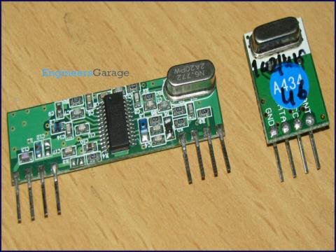
RF 433Mhz Transmitter/Receiver Modules
The following picture shows the Rx (left) and the Tx (right) Modules.

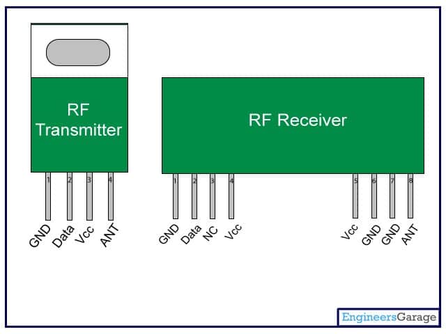
The following figure shows the pinout details of the above modules.
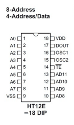
Encoder IC = HT12E
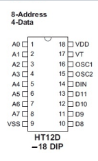
Decoder IC = HT12D
The above encoder and decoder ICs do the jobs exactly as per their assigned names that is encode and decode the bit information for enabling easy interfacing with analogue circuits.
After you have procured the above components it's time to put them together.
Assembling the Modules
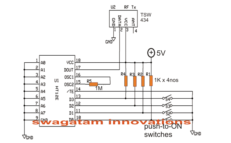
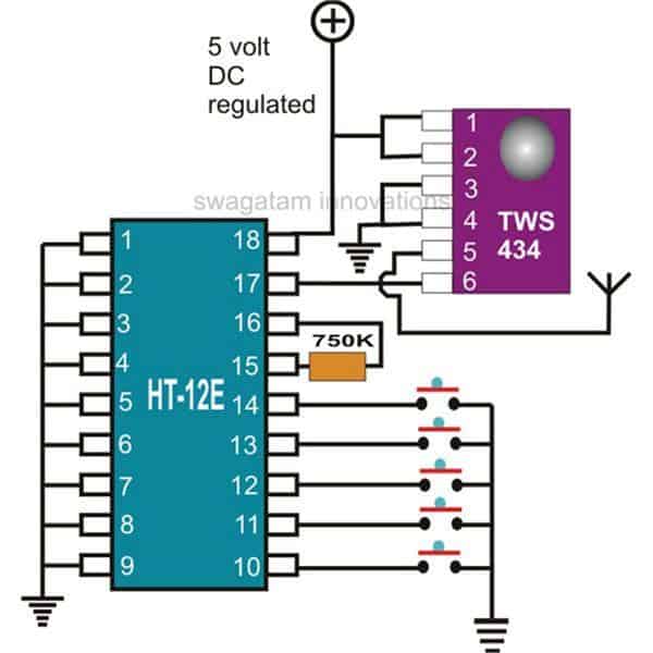
Configure the transmitter circuit by assembling the Tx (Transmitter) Module with the Encoder IC as given in the following circuit:
Next, assemble the Rx (Receiver) module with the decoder IC, as per the following diagram:
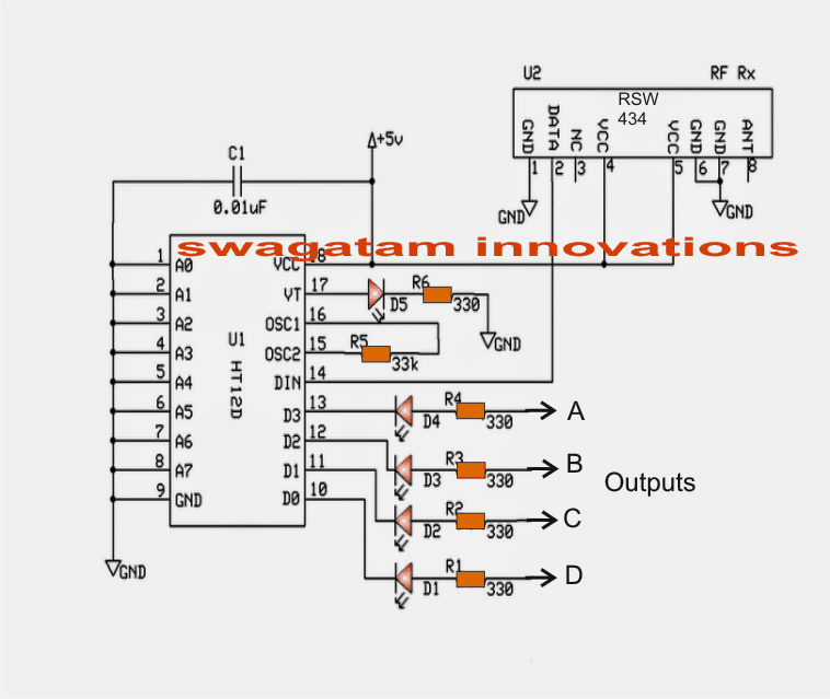
In the above Rx (receiver) circuit we can see that four of its outputs are terminated through LEDs at the points A.B,C,D and another output which is terminated via the VT pinout of the IC.
The four outputs A,B,C,D become high and latched in response to the pressing of the four push buttons shown in the Tx transmitter) circuit.
Pin13 switch of Tx influences the Pin13 output of the Rx and so on....
Suppose when output "A" of the Rx module is activated by the relevant switch of the Tx, it gets latched and this latch breaks only on activating any of the other outputs.
Thus the latch breaks only when a different subsequent output is rendered high through the Tx relevant push buttons.
The output from pin VT "blinks" momentarily every time one of the outputs A,B,C,D get activated. Meaning VT output can be used in case a flip flop is required to be operated.
The above can be very easily interfaced with a relay driver stage for operating any equipment such as a remote bell, lights, fans, inverters, automatic gates, locks, RC models etc.
How to Connect the Address Pins
The pinouts A0-----A7 of the Rx, Tx modules are very interesting. Here we can see them all grounded which creates an impression that these are of no use and are simply terminated to ground.
However these pinouts enable a very useful feature.
These address pinouts can be used for rendering a particular Rx, Tx pair uniquely.
It's simple, let's say for pairing the above modules we ensured that the address pins are identically configured.
Alternatively we could make the above pair unique let's say by opening A0 for both the modules. This will make the pair respond only with each other and never with any different module.
Similarly if you have more number of such pairs and want to make unique pairs out of them, just assign the pairs in the explained manner. You can do this by either connecting the address pins to ground or by keeping them open.
It means by rendering different configurations to the relevant address pinouts between A0 and A7 we can create a huge number of unique combinations.
The range of the above explained RF module is around 100 to 150 meters.
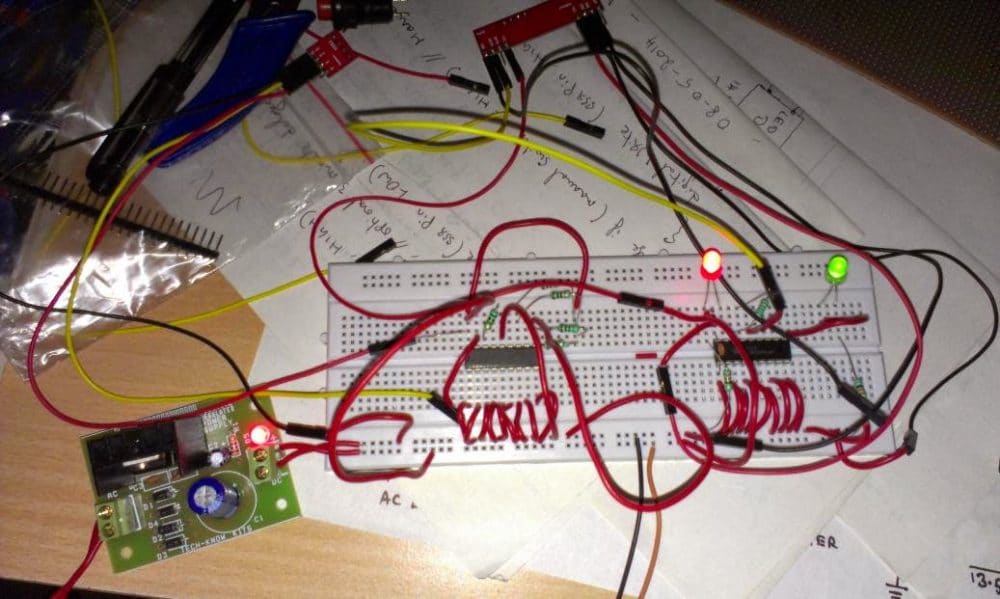
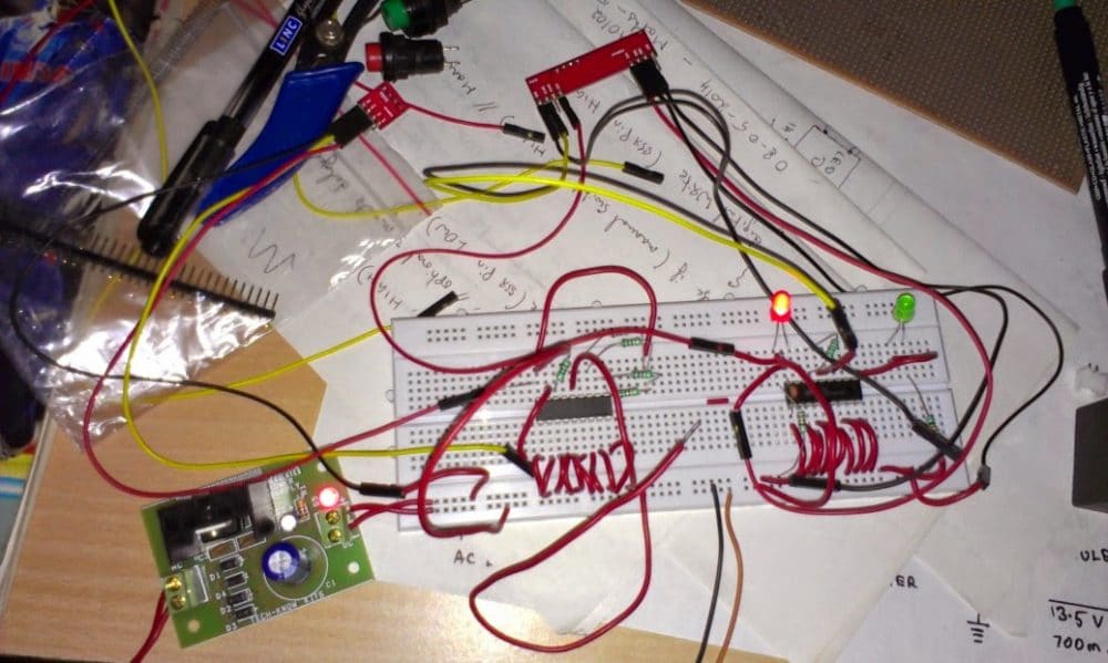
The above simple RF remote control circuit was successfully tested by Mr. Sriram on a breadboard, the following images of the built prototype were sent by him for reference.
Circuit Prototype Images
Making a 433 MHz, 315 MHz RF Remote Control with Relay Flip Flop
Building a hi-end remote control device using very few components today looks pretty plausible. The proposed remote control light switch circuit idea provides you with the opportunity of building and owning this amazing device through simple instructions.
Moreover the unit provides a 4-bit data to be exchanged between the transmitter and the receiver modules.
This Hi-tech remote control light switch enables you to control four individual lights or any electrical appliance for that matter from any corner of your house remotely using a single tiny remote control hand set.
Imagine switching a light, a fan, washing machine, computer or similar gadgets from any corner of your room without taking a step!
Doesn't that sound great?
Controlling a particular gadget remotely through a single flick of your finger definitely feels very amusing and amazing too.
It also gives you the comfort of doing an act without moving or getting up from a particular position.
The present circuit idea of a remote control light switch enables you controlling not only just a single light but four different electrical gadgets individually using a single remote control hand set.
Let’s try to understand its circuit functioning in details of the 433MHz Rx and Tx modules.
Transmitter (Tx) Circuit Operation
I have already discussed the wireless control modules in the above paragraphs, let’s summarize the entire description yet again and also learn how simply the stages may be configured into the proposed unit.
The first figure shows a standard transmitter module using the RF generator chip TWS-434 and the associated encoder chip the HOLTEK’s HT-12E.
The IC TWS-434 basically does the function of manufacturing and transmitting the carrier waves into the atmosphere.
However every carrier signal needs modulation for its proper execution, i.e. it needs to be embedded with a data that becomes the information for the receiving end.
This function is done through its complementing part – the HT-12E 4-bit encoder chip. It has got four inputs, which can be triggered discretely by giving them a ground pulse individually.
Each of these inputs produces coding which are distinctly different to each other and become their unique signature definitions.
The encoded pulse from the relevant input is transferred to the IC TWS-434 which carries forward the data and modulates it with the generated carrier waves and finally transmits it into the atmosphere.
The above operations take care of the transmitter unit.
Receiver (Rx) Circuit Operation
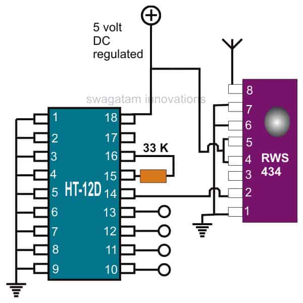
The receiver module does the above operations just in the opposite manner.
Here, the IC RWS-434 forms the receiving part of the module; its antenna anticipates the available encoded pulses from the atmosphere and captures them immediately as they are sensed.
The captured signals are relayed forward to the next stage – the signal decoder stage.
Just like the transmitter module, here too a complementing device the HOLTEK’s HT-12D is employed to revert the received encoded signals.
This decoding chip also consists of a 4-bit decoding circuitry and their outputs.
The received data is appropriately analyzed and decoded.
The decoded information gets terminated out through the relevant pin-out of the IC.
This output is in the form of a logic high pulse whose duration depends on the duration of the ground pulse applied to the encoder chip of the transmitter module.
How to use a Flip-Flop Relay Circuit at the Receiver module Output
The above output is fed to a Flip-Flop circuit using the IC 4017, whose output is finally used to switch the output load via a relay driver circuitry.
One such flip/flop idea is shown you may construct four of them to access each of the generated 4-bit data discretely and control four gadgets individually.
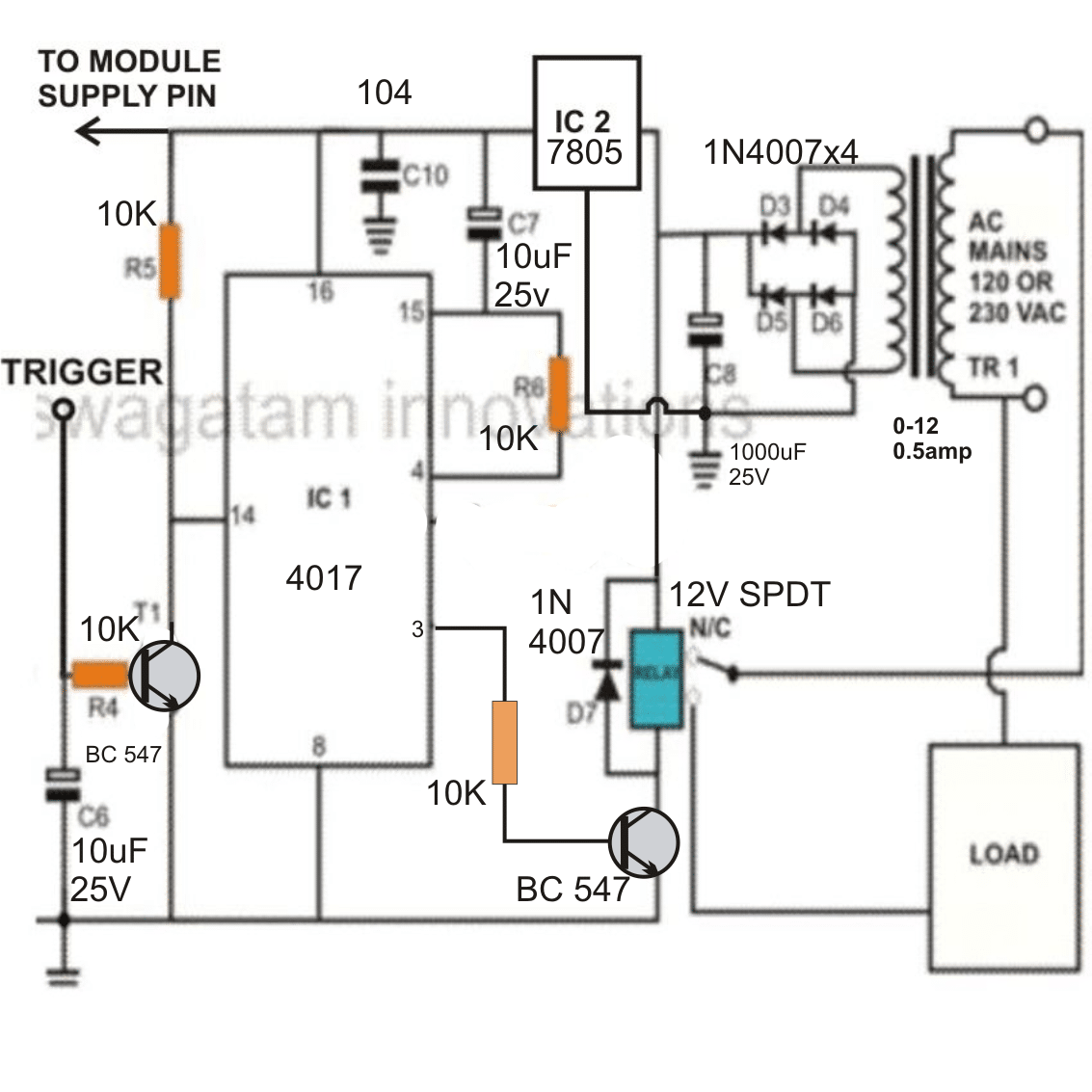
Whether you use it as a remote control light switch or to control many more appliances……the option is all yours.
How to get motor off signal
When the remote button is not pressed, the motor will be off…
Can you provide a link for where to purchase Transmitter/Receiver modules that will work with your circuit? Reviews of the ones I have say that they do not work at all, or only work with an additional antenna. Others that come with an antenna also have mixed reviews.
You can easily buy them from amazon, and these modules definitely work. The reviews could be from the users who could not wire the modules correctly, or they could have been posted by the competitors of that seller.
I have followed your circuit (and several variations I found online) with modules from two different sources and a couple different HT12E and D chips. I had a neighbor who is an engineer look at my wiring and agree that I followed your circuit correctly. None of my tries has worked either with or without antennas. Can you advise me how to troubleshoot the circuit to find out what is wrong?
As you can see the circuits are very basic and should start working immediately.
Did you try with LEDs at the output for the receiver design?
Make sure the LED resistor ends are connected with the 5V positive supply.
If still it doesn’t work then possibly there could be something wrong with your connections somewhere, or the ICs itself may be malfunctioning.
Thank you so much. One of the address wires to ground was broken. My hobby is Model Railroading and I know only a little about electronics, but a 10 yr old neighbor who stops here a few times a week and asks how to do things, wanted to build a remote control. Now that I can do it, I will guide him to build one too.
Oh, that’s great! I’m glad you could finally get the circuit to work. All the best to you!
Hello, how can I increase the range to 2 or 5 km?
Hi, sorry, it is not possible to modify the range of this IC beyond 50 meters.
hi sir, I have completed , but i m facing range issue, range is only 3 to 5 meter, i used antenna also, but don’t know what happen with range, i tried with different rf modules, but range not increased. plz guide me what i do……
Hi Ghulam, this problem is specific to your RF modules and beyond my control, so it will be difficult for me to understand and solve this problem.
Please use the RF modules separately without any load, with LEDs only and check the response first…
yes sir its working with npn transister, both relays are operating with remote now, once we press butten relay on and when leave relay off. now i want to add moter reverce and forward circut , in that circut with bc547 collecter you add 4.7k resister to positive and with s1, and on base 100k resister is connected with other side of s1, now these two points how to connect with 1st relay? for s2 bc557 emeiter is comnected with positive, base with 4.7 k resister connected with collecter of bc547. collecter connected with 100 k to s2, and other side is connected with negative, how to connect with relay 2? plz guide…… and while we are using remote, is it neccessary to add limit switch? because if remote butten pressed then moter will start, when leave moter will stop. plz guide me……
That’s good Ghulam.
In the following circuit if you release the remote button, the motor will not stop, because the transistors are latched. That is why limit switches S3, S4 are required.:
" rel="ugc">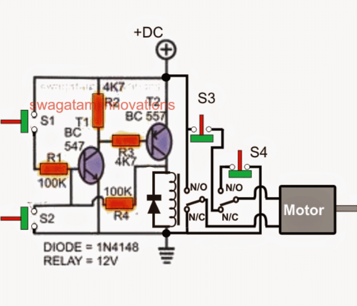
Remove the S1 switch, and across the S1 switch points connect one relay’s pole, and N/O.
Do the same for the S2 switch points, by connecting the S2 points with second relay’s pole, and N/O.
Hi Ghulam,
I have an update!
The following circuit has a problem.
" rel="ugc">
Suppose when the curtain is closed with the transistors latched, if mains power goes off and comes back then the latch will break and the motor will start reversing causing the curtain to start opening automatically.
Yesterday, I designed even a better remote controlled curtain open/close circuit which does not use any transistors rather only relays and can be configured with your remote control with perfection…
I will show you the circuit diagram soon.
hi sir if you have made this project can you share it with me im also a student of EET and making exactly the same project it will be really helpfull if you share the details
HI MR. Ghulam i hope you doing fine can you please share me your project details , im a student of electrical branch and im making the project Wireless water level controller using rf module and having alot of thing to understand about it if you will share me you project it will help me alot thanks
yes sir, i tried with bc557, but relays continusly on, sir what about the antena how many turn required? which wire is best for long range?
Ok, you can try the following transistor configuration for a 12V relay: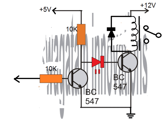
" rel="ugc">
The LED can be removed and replaced with a short jumper.
The Tx module already has an in-built antenna which is enough for a range of 20 meters, for higher ranges you can use a 1 meter long flexible wire, any ordinary single core flexible wire will work.
The coiling of the antenna is not required, it can be a straight wire.
thank you sir, you always make easy for me. a lot of thanks, i wipp try my best to make. now i have 3 circuts, 1 is for ht12d 2nd is cd4017 and third is moter circut, i will make these 3 circuts combine, in this situation with 2nd circut cd4017, in this relay is nesseary or can we give power from bc547 to 3rd circut moter reverse forward. with limit switch…..
You are welcome Ghulam,
The 4017 IC circuit will not be required, you just have to replace the S1, S2 switches of the gate open/close circuit with the relay contacts of your remote receiver, that’s all.
sir like i required only ht12d circut, and at out put a and b i need to use relay, and from relay terminal give power to s1 and s2, thats it ryt?
Ghulam, you are right!
Connect separate 10k resistors with point A and point B.
Connect separate BC557 transistors at the other end of the 10k resistors.
Connect separate relays across collectors of the BC557 and ground.
Connect 1N4007 diodes across the relay coils.
Connect the emitters of the BC557 transistors with the positive supply.
hi sir, hope all is going well, sir i assembled as you guide, but i am facing issue, before i make water pump controler with rf module, i used ht12d and ht12e, and uc2003 ic, as password i connect all pins, 9 to 1, now in new project i changed password but receiver section catching signal from old one, even pins password is changed for both side, (rx and tx), where is the issue? i have green rf module.
Hi Ghulam,
Pin#9 must be connected to ground, only the pin#1 to 8 must be configured uniquely for different pairs of Rx and Tx.
The above configuration must be the same for the Rx and the Tx pairs.
If you configure the pin1 to pin8 differently for two different pairs then they must not interfere with each other.
Please try a different configuration once again and check the results.
However, if the two units are operating too close to each then maybe the systems can interfere with each other.
sir i tried and now its fine, but as you guide use to bc557 with relay, sir i give power to ht12d from 7805, signal led and output led is ok, but relay not on, how to make connection for 12 volt relay, bc557 emiter from where i can give positive? from 7805 out put or direct from 12 volt? plz guide
Thanks Ghulam,
If you are using a 12V relay, then the emitter of the BC557 must be connected directly to the +12V DC, not +5V.
+5V must be used only for the remote control ICs.
Relay coil must have a 1n4007 diode in parallel, cathode to BC557 collector and anode to ground.
Ghulam,
Sorry, connecting BC557 emitter to positive is wrong for a 12V relay, it will not work…
If you are using BC557 then only a 5V relay will work.
For 12V relay you will have use two NPN transistors at the output of the Rx IC.
I will show you how to do it soon…
Hi Swagatam
Thanks for clearing that up!!!! You are the best!!!
You are welcome Norman..
Hi Swagatam, In the above article with reference to the receiver circuit, you say the A,B,C,D become high and latched in response to the pressing of the push buttons of the transmitter circuit. That doesn’t seem right as you show the LEDs in those lines to be connected backwards. Also in another post you show the LED connected correctly and you are using a PNP transistor. I also posted on that page. Please confirm the outputs of the HT12D to be negative when triggered by the TX/RX modules.
Hi Norman,
I have replied to your previous comment in the other post, please check it.
Yes, there’s a typo in the above article, the term “high” must be replaced with “low” because as per the test results from one of the users the outputs A, B, C, D from the receiver are supposed to become low upon receiving a signal from the transmitter.
These relevant receiver outputs might get latched if the signal from the transmitter is selected to operate in a latched mode (flip-flop mode)
Hi, I am trying to make a circuit for wireless communication using a 433 Mhz transmitter and receiver with 1 LED connected to each board. The LED on the transmitting board will indicate whether or not the board is tuned on and the LED on the receiving circuit will be activated when a signal is sent.
I would highly appreciate if you could inform me on what materials and equipment I would need in order to build this system.
Hi, the configuration details are provided in the first two circuit diagrams. You just have to build those two circuits for your application, and use one of the four transmitter buttons and the corresponding receiver output. Also, you will need to connect the relevant LED resistor end to the 5V positive supply, A, B, C, or D, whichever corresponds to the selected transmitter button.
I highly appreciate your fast replies Swagatam. I have a few more questions regarding the circuits though.
Would it be possible to make this circuit using PCB’s instead of breadboards? What software did you use to design the schematic circuit diagrams? What are the outputs A,B,C,D and the resistors 1,2,3,4 meant to do when the signal has already been received and shown on each LED, would it not be possible to connect the circuit to the ground after each LED?
Thank you Karl,
Breadboard is strictly not recommend, it should be built only on a well designed PCB.
However designing PCB and assembling the circuits precisely can be quite tedious and complex, therefore I would rather recommend buying tested ready made units instead with all the facilities added.
Here’s an example of the unit matching my recommendation. You can search the following which is available from amazon:
INVENTO 433Mhz Wireless RF Transmitter Receiver Board With HT12D HT12E upto 150 mtr range for DIY Projects
The resistors at A, B, C, D points must be connected to the +5V line otherwise the LEDs will not illuminate.
Thank you so much Swagatam! Please correct me if I am wrong but the list of materials needed to create the wireless communication system (with 1 LED) would be:
What software did you use to create the first two schematic circuit diagrams?
Hi Karl,
Yes all the components are almost correct except the 1 million ohm resistor which is actually a 1 Mega Ohm resistor.
All the resistors can be 1/4 watt 5% CFR and the capacitor can be a ceramic capacitor.
The LEDs can be 3.3 V, 20 mA, 5 mm type.
I used CorelDraw.
Thank you so much Swagatam! I cannot explain to you how grateful I am that you have helped me.
Thank you Karl, It’s my pleasure!
Would a 4.5 volt battery also work?
5V is the recommended supply input, 4.5V might not be sufficient.
Would I be able to take apart the different parts of the circuit without damaging any of them from the link you provided above?
What is the meaning of the parts on the encoder and decoder labelled A0 – A7?
That wouldn’t be advisable. If you want to assemble the whole circuit individually, then I would recommend getting all the spare parts separately.
A0-A7 are address pins. The configuration of these pins that you use on the transmitter board must be exactly replicated on the receiver board also so that they can be paired with each other and they correspond correctly with each other.
Do you know where I would be able to find these parts?
You can get these mostly from amazon.
For the PCBs needed to actually combine all the components together, would I need to design the PCB myself or is there a prototype like PCB which I can purchase and use to create the circuit?
I think you will have to design your own PCB design, ready made PCBs may not available. Or you can contact a professional PCB designer for the job. However ready made pre-assembled boards might be available.
Would it be difficult to learn the necessary soldering skills in order to combine all the components of the wireless communication system together?
If you are a newcomer to electronics then it can be very difficult to learn everything from the start and assemble this circuit.
where could I learn how to assemble this circuit?
Learning electronics is a long long process which cannot be mastered within a few days. First you must try building small noncritical circuits successfully, once you are well versed with the soldering and the troubleshooting them, only then you must try assembling critical circuits like the above.
There are many you tube videos where you can learn how to solder correctly.
How long would it take to only learn the skills that are necessary to make this circuit?
It is impossible to learn good soldering without practising. The time depends on how well you learn the process by assembling many small circuits.
Even if you learn soldering and assemble the above circuit, and if it has problems how will you troubleshoot it?
Would it be possible to practice assembling this circuit until it worked?
Yes that may be possible.
If the circuit were to be operated at 12 volts what would I need to change about the components I am already using such as the capacitors and the resistors?
The circuit needs to be operated strictly with a 5V supply, if you have a 12V supply then you will need to drop it to 5V using a 7805 regulator IC. Nothing else needs to be changed in the circuit.
So the 7805 regulator would be placed in between the 12v supply and the rest of the circuit?
Yes that’s correct. Here’s an example setup using 9V as the input. You can ignore the capacitors they are not required.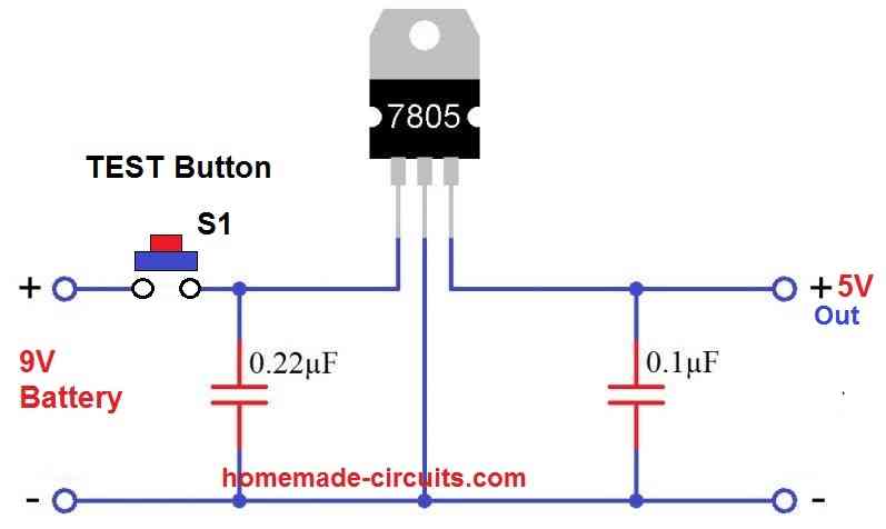
" rel="ugc">
And the 7805 voltage regulator IC would also work for a 12v supply?
Yes, it can handle 12V… it can work with input DCs upto 30V.
Im guessing that I would not be using a typical 12v battery so what would I be using as the 12v supply instead
You can use any DC source that you may access to.
Why is there a mega ohm resistor between the 2 open sound controls in the first schematic?
That’s as per the standard configuration of the circuit. You may have to refer to the datasheet of the IC to get more info about it.
Would it be possible for me to send you the adapted circuit diagram I created and have you check if everything is correct?
You can send it to my email address, which is given in my contact page. I will check it…
I saw your diagrams in my email. You have short circuited the ground line the Vcc line or the positive line of the circuit.
Make sure the 7805 ground pin and the input DC ground supply are connected only with the circuit’s ground line, and not with the positive line.
In short, please isolate the 7805 ground supply from the positive line.
Hi Swagatam, would it be possible for you to show me how the schematic circuit diagram should be drawn?
Hi Karl, please see the diagram below, and do the connections as given in the diagram: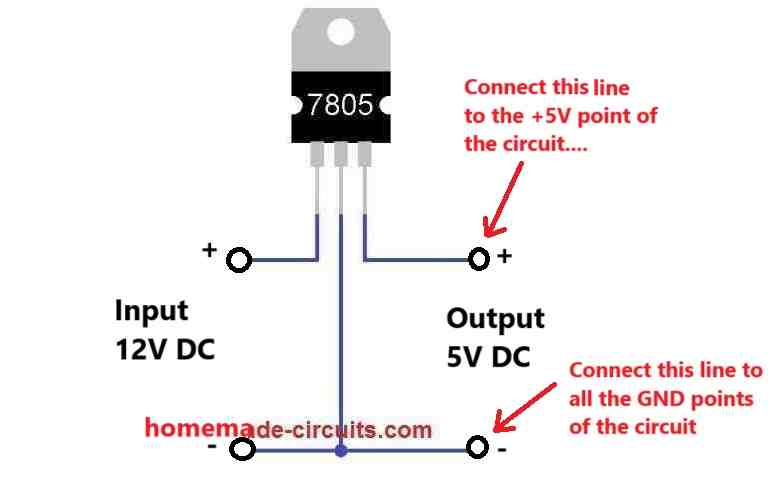
" rel="ugc">
I do not know where I would connect the negatively charged wire and where I would connect the positively charged wire. would it be possible if you could draw out the circuit diagram? I would greatly appreciate it.
Are you able to get 5V output from your 7805 regulator?
If yes, then you simply have to do the following.
Can you see the points marked as “GND” in the diagram? Those are the negative points, so the negative wire from the 7805 power supply will connect with these GND points.
And the +5V from the 7805 will connect with the points marked as +5V in the circuit diagram.
Please let me know what exactly you can’t understand in the above explanation, I will try to help further.
Hi. I want to make 433 Hz Jammer circuit with a range of 75-100 m. Can you help me with regards to that please?
Hi, sorry, presently I do not have this specific circuit design with me.
hi
i need schematic diagram rf 315/433 mhz remote control tester
you have schematic for tester remote control
i need check frequency remote control with tester
best regard
Hi, you can try building the following circuit for measuring the frequency:
https://www.homemade-circuits.com/frequency-meter-circuit-using-arduino/
Hi Swagatam,
I am trying to build a 433MHZ wireless alert that triggers a music chip ic to play one of 12 different melodies each time someone enters my front porch area. The ic is triggered by a falling edge signal. The PIR that I am trying to use is an AM312. It triggers on for 2 seconds and has a blocking time of 2 seconds. I am trying to have the circuit only trigger one of the twelve melodies each time a new person approaches my front porch. The way it is now the music chip advances each time it is triggered due to the 4 second combined delay. So when a person approaches it triggers and triggers again while the person is still in the area. I have tried to figure out some way to delay the retriggering with no luck. I used a 104/105 capacitor with 1m resistors to ground inline with the PIR output which sort of worked, but retriggers when the capacitor drains off. I’m sure if there is a way to use the PIR selected, you will be able to figure it out. I am attaching two sizes of my schematic as I don’t know how they are displayed on you computer. I am also posting my problem under one of your 433mhz wireless topics on your site. Thanks for your time and expertise!
Hi Norman, I guess you want the relay not to respond to the OFF times of the PIR triggers, and remain switched ON continuously, as long as the PIR is pulsing?
This can be probably solved using the following diode/capacitor timing network at the base of the relay driver transistor:
" rel="ugc">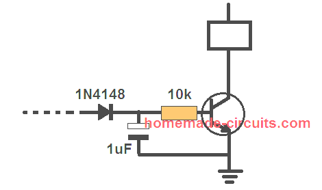
Hope it works.
Hi, is there any circuit available to stop the system latching, when the MOM switch is pressed regards Brian
Hi, the momentary On/OFF option is already provided in the remote control handset.
Hello Mr.Swag, I want build this circuit, but i have question.
I want this circuit work like this , if the switch transmitter S1 ON ,the receiver is ON, if S1 is OFF the receiver is OFF.
How to modified circuit . Thanks
Hello Sarwana, it is supposed to work exactly in that way!
Ok, thanks for answer. You very fast respon to answer question. I appreciate what you do. Godbless you Mr.Swag
You are welcome Sarwana!
Hi , to start , I love the site and appreciate what you do!
How would I add a throttle to the remote? Like a thumb throttle! If the throttle used a 10k pot to vary 5v
from 0-5 I would think I’d convert it to pwm to transmit over the RF , Then I’d have to do the reverse on the receiver end. My ESC is voltage regulated not PWM. I originally wanted to use a wired throttle but I’d have to attach and detach it for each use ( assembly is in 2 parts) then I could leave the remote attached to one part and the receiver on the other !
Pete
I should mention part 2 of this in that I’d also need the max power to be delayed over 2 seconds even it the throttle is swung up to max, I need the power to be applied smoothly!
thanks in advance
Pete
You can try the soft start design as the PWM generator for the transmitter, this might solve your 2nd problem also:
https://www.homemade-circuits.com/pwm-motor-soft-start-circuit/
Hi, yes that’s possible.
As you can see the transmitter inputs are configured with ON OFF switches, which means those pinouts are designed to accept logic high low signals. You can select any one of these pinouts to send the PWM to the transmitter. The PWM circuit can be built with any standard IC 555 circuit.
I am not sure why the reversal is needed at the receiver side, but if you need it, you can do it with a simple BJT inverter circuit, using a PNP BJT
The reason I asked about the reverse is because I ordered a pre-built remote that does reverse. The receiver has 3 leads coming out 5v,gnd and pwm signal! I can’t figure how they get a reverse. Hmm unless they use 0-50% of the PWM for forward speeds and 51-100% for reverse.
Thanks
Pete
Yes, just remembered that the receiver (Rx) does produce 0V logics in response to high logics from the transmitter, in that case you will have to use a PNP transistor inverter stage for reversing the logics.
OK i just realized the TX-RX units would have to be paired as I might have many units in close proximity and its of utmost importance that they is NO interference!
I think with these rx-tx units the can be assigned a channel but it won’t be exclusive!
Would a blutooth system work like I want and is it very complicated!
Pete
As far as I know, the address pins of the Tx/Rx ICs can be configured uniquely for creating exclusive Tx/Rx pairings, as explained in the above article. Bluetooth can be also applied for the same.
sir can i use kits from toy car (remote control) for this purpose.
means for inverter on/off, charging on/off
Hi shankar, yes you can do that!
Can I use the same circuit with 12 volt supply as i am using 12v dc motors in my project and i want to start those motors remotely or some more things need to be ad in this circuit.
you can use 12v for the motor but you will have to step down the 12 V to 5v using 7805 IC for operating the IC circuits.
Do you know how much latency (ms) there is between transmitter input (switch closure) to receiver output?
I have a timing application and need minimal latency OR simply to know how much latency (if it’s consistent).
Thanks in advance.
Hello sir Swagatam,
Nice update on your website!
Please do you have any article on your website on ESP8266 Wi-Fi module or associated circuit? If you do, kindly help me with the link.
Thank you.
Hello Godson, presently I do not have the mentioned article, if possible I’ll to investigate and update it.
Hello sir Swagatam,
Thanks a lot for the correspondence the past days.
Please I need your help on the following:
1. I need the part number to encoder and decoder ICs (that works exactly like HT-12E and HT-12D) that has more than 4 output pins, and that can work with the RF modules in the schematic above. I’ve searched the internet without success.
2. I need the part number to an IC or ICs (preferably 400series ICs) that works like CD4017. The IC should have different clock input pins and their corresponding output pins in the same IC, such that when a clock pulse is received in one of the clock inputs, it turns on its output and turns off any other output that may have been turned on before it. i.e only one output stays on at a time and any of the input may receive their signals separately.
I can also make do of an IC that can receive continuous positive or negative signals in its input and and activate its corresponding output and turn off any other output that was previously turned on before it.
I know that I can achieve this using PICs but I have no knowledge in programming.
Your response will be well appreciated sir.
Hi Godson,
you can try searching “433 MHz 4 channel module” might help you to find an alternative for the HT modules
for flip flop versions, you could look for IC 4022, or IC4013, here are a couple of links that you could investigate
https://www.homemade-circuits.com/make-this-easiest-flip-flop-circuit/
https://www.homemade-circuits.com/build-these-simple-flip-flop-circuits/
Thanks a lot for the reply sir. The links were helpful. I will make use of IC4013 flip-flop to achieve what I want to achieve.
I found an 8channel 433MHz encoder and decoder modules on the internet after a long search. Their part names are HT640 and HT648L.
You are welcome Godson, you can look for “Linx” RF modules
Hello sir Swagatam,
Thanks a lot for this circuit. I have built it and it’s working well with a good range too. I have a challenge though. I want to use the circuit to operate four relays through the four channels, using a transistor driver stage, in such a way that when one button is pressed in the Tx session, the corresponding relay in the Rx session stays activated until the button is released.
From what I observed after testing, the configuration works in active-low mode. The output of the Rx IC is low on receiving the signal from Tx and high when no signal is received. I have tried connecting it to a transistor driver stage using BC557 transistor, but it didn’t work. I also tried BC547, the same result. The relays latch on even when no button is pushed. Kindly suggest a solution to the problem.
Anticipating your usual prompt response.
Thank you sir.
Hi Godson, did you connect LEDs with the outputs? if not please do it. LED will give a clear indication regarding the response from the output pins.
BC557 should work, make sure you have connected its pinouts correctly.
The supply to the relay should come from a 12V source while the supply to the IC should come from a 5V source.
Hello sir Swagatam,
Thanks a lot for the prompt reply. I have done exactly as you said and I am still experiencing the same problem.
Here is the situation:
•For testing purpose, I connected the cathodes of the LEDs to the output of the Rx IC and their anodes to the 5V supply. The LEDs turned on and off as the buttons are pressed and released in Tx.
•But as soon as I connect the anodes of the LEDs to the 12V supply via resistors, they remain turned on (though a little faint) even when no button is pressed in the Tx. When a button is then pressed in Tx, the corresponding LED becomes brighter while others go off.
•This same situation plays out when I connect the BC557 through the LED as shown in the schematic above. The LED is turned on faintly when no button is pressed in Tx, which in turn turns on the BC557, and consequently, the relay stays on. I have tried increasing the value of the base resistor of BC557 but no change. When I increase the resistor to a point, the BC557 is not turned on at all.
It appears as though the outputs of the Rx IC is “leaking” when connected to the 12V supply.
What can be the cause of this problem and what solution can you profer?
Hello Godson,
I am sorry…that’s right, the BC557 will be always ON since it is continuously getting the biasing voltage through the 5V – 12V = -7V, that’s seriously wrong.
In this situation please use two BC547 in inverter mode, as shown in the following example image:
" rel="ugc">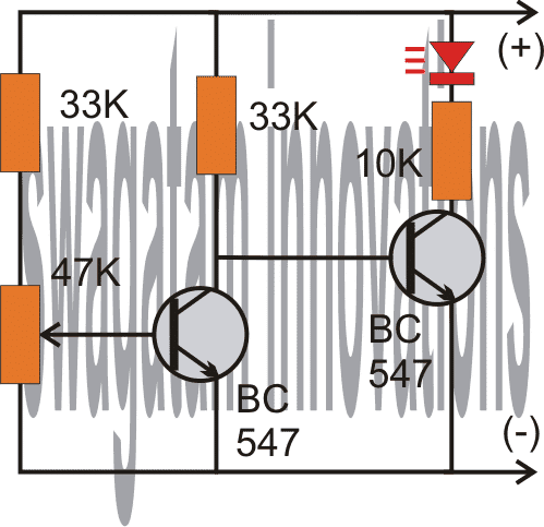
Replace the LED/resistor with relay coil/diode….make sure to connect the relay to the +12V supply, while connect the remaining left side positive line with +5V.
ignore the preset and the 33K resistor, and connect the left side BC547 base with the IC’s LED/resistor output.
Let me know if you have any more doubts
Thank you very much for the response sir.
I have connected the outputs of the Rx with the circuit shown in link that you provided. I removed the 47k pot and the 33k resistor on the left and connected the output of the Rx IC through the LED/resistor, to the BC547 at the left. But the result is the same. The relay stays on whether a button is pressed or not. I removed the second 33k resistor in the middle and the relay stays off even when button is pressed in Tx.
I then decided to use only one BC547 with a 1k base resistor, and the relay stays on when no button is pressed, and goes off whenever the corresponding button is pressed. But that is not how I want the circuit to work. I want the relay to turn on only when a button is pressed.
I believe that there must be a solution to the issue.
Hi Godson, please remove the LED from the IC output pin and connect it at the base of the right side transistor. please see the modified design below:
" rel="ugc">
Wow!
It’s working perfectly well now after I implemented the modified design of the transistor driver. Thank you so much for your assistance sir. Keep up the good work!
Glad it’s working Godson, keep up the good work!
Hi Swagatam
is it possible to connect a visual display like LCD wireless without any microcontroller?
thanks in advance
Hi Abba,
visual display can be connected, but what do you want to send in this display? or what do yo intend to see in the display?
Hello swagatam,
awsome site, im glad I stumbled upon and well written, TY
my question is for the pin outs,
I see in the actual pic of modules the Tx has identifiers on the back side witch matches your drawn pic for pin id, does the Rx module have to same identifiers on its back side ?
if not, is your drawn pic of pin identifiers done by viewing the Rx from its back side (none circuit side) ??
just like the Tx reference..
TYTY in advance, P1nki3
Thanks P1inki3, really glad you liked my site.
The pinouts are identified from the top view, please refer to the following article, I think this might help you to get it correctly
https://www.homemade-circuits.com/rf-remote-control-encoder-and-decoder/
Thank u Sir for this information..
Nee some help and advise based on this circuit.
Im working on a micro rc plane which will be controlled using 2 motors. The Tx will have 2 joyticks one for throttle which controls speed for both motors and one which will speed up each of the motors depending on joystick position.
My questions are.
1) Can i use the above circuit for the same and what modifications would i have to make for joystick and motors. Will this circuit accomodate PWM signals?
2) Can i use potentiometers as my joysticks or any other alternatives?
3) can the range on the RF modules be increased? Would an antenna help substancially?
Deeply appreciate ur help in these matters
My email is [email protected]
Thank u Sir.
Hi Rohan,
yes you can connect PWM and pot control with the above RF module Rx unit, and control the motor output at the Tx side accordingly, but I am not sure how a joystick could be configured with a pot?
The range can be increased by increasing the Tx antenna length using a 1 meter flexible wire or a telescopic antenna.
I have already discussed a similar concept in the website, you can refer to the following link for a better understanding of the concept:
https://www.homemade-circuits.com/2015/10/quadcopter-remote-control-circuit.html
Sir, can i use this circuit with pwm signals to have a potentiometer instead of switches at tx end and use the pwm signals to drive motors at rx end? Would the same circuit work?
What i i want to drive 2 motors and change the speed of each motor or wen shut one off and let tw other run.. How do i modify this circuit for that?
Also what beat range will i get from the 433rf units if i attach the 17.34cm antenna on both ends?
Much appreciate all the infprmation.
Thank u Sir.
hello swagatam i'm shubham
i build the circuit using rf technology with pic controller to turn on the light through relay
when i press the key from the transmitter side there is no quick repose across the receiver to turn the light on i need to press the key continuously for more then 5 times after that it is turning on so
sir im not able to find out the problem is this problem causing by the hardware or by the software and i tried with different baud rates like 9600bps and 4800bps so sir how i can avoid this problems please suggest something
Hello Shubham.
If it's a MCU based then it could be difficult to troubleshoot through assumptions, since the problem could be obviously in the software section or the coding.
If you have programmed it then I think it shouldn't be much difficult for you to track it down
Output rx i use PNP transistor and connected to 4017 14pin means it will work sir…
yes it will work
Hai sir….
I have few ? Sir…
When Tx 1 button active means Reciever output D0 output will be postive or negative..
For one tx pressing second it will work or it will latch it sir
I'm going to use this circuit in CD4017..
.If Rx D0 o/p postive means shall i connect 14 pin in cd4017…
In the between of 4017 14 and RX DO pin i use one diode IN4007…is it correct sir…
Whether the D0 o/p negataive means shall i 470ohms resistor and 557 transistor…
Pls give the solution sir..
Hi Kesava…in the above circuit the output from the Rx was tested to be negative when triggered…and positive normally when not triggered.
you can connect the 4017 pin#14 directly with RX outputs but due to the opposite effect the 4017 flip flop will toggle only when you press and release the Tx button.
do not connect any diode or resistor in between the Rx output and 4017 pin#14.
….your ebay link RF modules are OK….
Hey, how do I do that when I turn on the light in the room, the LED output is on and when I turn off the light in the room, is turns off the LED output? TX module wanna be powered directly from the light. That is, when I turn off the light, TX module power is off and also the state of the RX LED changes. Thank you.
I could not understand your requirement.
…you can do it by replacing the switch points with BC547 Collectors/emitters.
the bases could be connected at the junction of an LDR and a 220K resistor. 220K end would go to the ground…and the LDR end to 5V supply
hey how hard can it be to make the same job from scratch i mean using oscillators , modulation circuits , antenna … in much lower frequencies 5 mhz ?
almost impossible, even if it's made it would'nt work as efficiently as the above explained design
Well Sir, I just breadboarded your circuit an could not light any of the four LED…A,B,C,or D..The led for VT blinks so I know there is some transfer, but I am not sure what to do next.
Caleb, check the polarity of the LEDs, it must be exactly as shown in the diagram….by the way unless the points A,B,C,D are connected with some source the LEDs will not show any response….so make sure these are connected to a transistor driver stage…… or for testing purpose you can connected them with the supply rail of the circuit.
how to make remote for toggling mode for controlling home appliances
https://www.homemade-circuits.com/2016/06/control-8-appliances-with-single-remote.html
Thank you very much Swagatam!
I will try this out at once and let you know the result.
You are welcome Henriks
Dear Swagatam,
I really enjoy your site. Thank you.
I have built your RF circuit (Simple RF Remote Control Circuit without Microcontroller).
I work well. The led light up when a button on the transmitter is pressed.
I would like to add a relay to each output on the receiver which should be latched until the respective button on the transmitter is pressed again (On/Off).
What do I have to add/modify in order to make this work?
If I set the address like this:
Transmitter pin 1-8 to ground
Receiver one of the pins 1-8 not to ground and turn on the power an led on the receiver lights up and keeps so until I change the address.
How does that come?
Thank you in advance,
Henrik
Thank you Henrik!
To latch a relay you may have to employ a flip flop circuit, such as a 4013 flip flop
https://www.homemade-circuits.com/2012/05/make-this-easiest-flip-flop-circuit.html
remove all that's connected with the CLK pin and connect this directly with the relevant Rx output pin.
I am not sure why the LED lights up with a different address pin configuration, may be it's trying to indicate that the Address pins of the Tx/Rx do not match each others….
many thanks, can you suggest a suitable npn transistor?
it will depend on the current consumption spec of the circuit, if it's below 1 amp you can use a 2N2222
Heelo Mr SWAGATAM MAJUMDAR, can you please inform if is possible use your example, but running in 16 outputs not 4 outputs, like this post? regards
Hi Paulo, yes you can use the same set-up for a 16 channel Rx/Tx module also, just repeat the suggested configuration for the all 16 i/p, o/p pins
Hello Swagatam,
I wish to use the output of VT to close a small 12v circuit but I do not want to use a relay. Can you tell me the voltage and current at VT when the signal is received? I want to try and use an SCR to close the 12v circuit
Hello Dan, you can connect the free end of the 360 resistor with the base of a NPN transistor, and connect the emitter of the transistor with the ground rail.
Next you can connect the 12V circuit between the (+12V rail) and the collector of the NPN, and make sure that you join the 12V negative with the 5V negative of the above circuit
an SCR will latch permanently….so it might not be suitable
sir can we put power amplifer for long rang up to 1km to 2km for my rcplane
sorry that may not be possible with this module
Hello sir.. I have to do rf remote controll transmitter and receiver. At receiver i have to use Pic16f877a and to drive motor on the rf remote controll. What should i do? Please suggest me.
Hello Vicky, I am not good at programming MCUs so this won't be possible from my side…..
Hello, very thanks for the post!!! If i need to make one project using your idea with hts 12 to control 16 relays, is it possible? can you show me one simple application of these if is possible? regards
yes it's possible if the module supports 16 outputs ports.
normally this circuit is used to give latched output.Means works as a toggle switch or oN/OFF switch.Can we use some outputs as On when pushbutton is pressed & Off when pushbutton is released.
What do we call such output technically?
this feature and a few more can be found included in ready made units, you just have to tweak the given connector modes and get the required features. You may find this in the unit as shown below
https://www.homemade-circuits.com/2012/08/how-to-buy-and-use-rf-remote-control.html
cai i use HT12D or HT12E for RF315 modules.
I am not sure about that, better to buy it ready made
thank u
dwagatam ji i checked the circuit .
this problem is present for every car center lock.
i need solution for RF 434.
can i add circuit on RF 434 module to remove noise.
or i can replace RF434 with RF 315..
i want to use RF modules .
here is any solution or upgradation of circuit.
thanx.
Prashantji, so does it mean jamming car remote systems is so easy? It looks very strange.
anyway, as far as modifying is concerned these remote units are embedded units and cannot be modified in anyway, so there's no external solution available for the issue.
yes you can try replacing it with RF315 this could make a difference…
thank u swagatam ji .
plz send me link of fm based ordinary transmitter and receiver circuit.
fm base transmitter and receiver can give code for different systems.
and 40 meters range in home conditions.
Prashantji, the circuit which I am referring is an ordinary FM transmitter and FM radio circuit which are modified as a remote control…the details are given here.
https://www.homemade-circuits.com/2011/12/how-to-make-fm-remote-control-using-fm.html
thank u swagatam ji .
plz send me link of fm based ordinary transmitter and receiver circuit.
Dear swagatam ji actual problem with RF receiver and transmitter is.
we r making water pump controllers for domestic pumps using RF 434 with coding ht12e and ht12 d.
problem is if i fix wireless system at any home.
the wireless works properly .
but its range effect jam all the center lock of car in range.( centeral lock remote not work till RF434 on).
what is the prob with RF434 mhz
i m use red modules with rohs approved.
Prashantji, Then it's the problem of your car remote control, you should complain this to your dealer from where you purchased the car security system….because these units are supposed to be immune to all forms of RF waves which are not directly matching their specified wave frequency.
or possibly you can quit the RF module remote control for the water level controller and use an FM based ordinary transmitter.receiver circuit which will not interfere with your car system
Dear swagtam ji
I m using this circuit
Rf434mhz with ht12e and ht12d.
Here is big problem.
If we supply the receiver and transmitter .
Car centeral locking system remote not works in wireless range.
Plz send me solutions
Dear Prashantji,
First try it on table and confirm the working, after this you can try it inside the car.
Put a long antenna with the receiver unit, this could be a two meter long flexible wire joined with the existing antenna of the Rx unit.
This module Is that possible to use in helicopter, drone?
yes if it's upgraded with a joystick facility
sir help me about one light off because suply off automatically but again supply on second light on not a light first.these drawback remove .why?
do you mean to say that you want the outputs to latch and hold when the relevant remote buttons are pressed?
sorry that may not be possible in this module, you may have to buy ready made modules which normally include a selection option for the output modes.
Hi Bruno, you can get it from any online parts dealer.
for getting a positive logic you will need to invert the output by using NPN transistors across the 4 outputs or by using NOT gates.
four led connected by using rf remote control switch,first light on after sometime supply off but again supply on swtich on light second glow not a first light why.this drawback remove name of component remove from this circuit
sorry, your English is difficult to understand please explain in proper English.
Hi Majumdar! can you tell me were i can buy the tx and rx modules?on rx module it is possible to have outputs with ground connection pulse?
regards, Bruno
My decoder is not giving vt op
My receiver decoder is not getting vt op led is not blinking
i'm working on the amplifier but it is hard to find transistors working at 433mhz frequency, developing a transmitter module operating at fm band as receiver boards are readily available, i need fm transmitters with crystal oscillators, any crystal fm bug circuit sir ?
thank you for the valuable information Seelamseti, I hope it helps the interested readers.
sir range can be increased by rf wide band amplifier at transmitter side we can increase its range ,without modifying circuit simply use an 12volts pencil cell for the transmitter(cell used in car centre locking system) i referred the data sheet for 12volts db is increasing
hi
is the ABCD output enough to be valid logic 1 for logic circuits?
yes, all are 5V compatible
Hello Sir,
can you guide me an simulator software where i test this circuit.I use proteus 7.8 but there is no RF module in its library.. can you guide me.. kindly reply me thank you
I am sorry, I don't have much idea about simulators software, because I never use them….they are not worth trusting
Hi Mr, what is the difference between a simple resistor 1k and a 1k x 4nos resistor? a ceramic resistor? can I replace it with a simple resistor? thanks
you can use ordinary carbon 1/4 watt resistors for the above shown circuits
P.S.
4. How much is the power supply?
power supply is 5V.
the 2 way remote control article which you referred does not have a clear explanation or a diagram so it won't be feasible for me to elaborate on that.
Yeah you're right… -.-…so blur…can't even understand where to put the antenna…
Hi Swagatam,
I was wondering? :
1. The pins from A0-A11/1-8 & 10-13 of the HT12Encoder, are they all switches? I mean for basic wireless on/off switch?
2. If yes, how do I add more switches? Will I add 1Kohm resistor with one end connected to pin 18/VDD and the other end to pin A0-A11/1-8 & 10-13?
3. Better yet, can you modify the whole ciruit to make remote controlled car?
* The circuit should consist of:
-Motor A & B
-Switch A, B, C, D
-Press switch:
-A: Motor A turns clockwise
-B: Motor A turns counterclockwise
-C: Motor B turns clockwise
-D: Motor B turns counterclockwise
-Encoder/Transmitter
-Decoder/Receiver cricuit
plsss..Thanks!
Hi eshkariel,
A0 to A11 are address pinouts of the ICs, these are for enabling different frequency combinations to be set by joining these pins across each other and the ground thus allowing unique Rx, Tx sets to be generated.
I have already posted a toy car circuit in my blog, you can study it here:
https://www.homemade-circuits.com/2012/09/make-remote-controlled-toy-car-circuit.html
Hi swagatam, thanks for the detailed reply, i am now in the soldering stage (learning). will update once it is done.
all the best to you Rajnikanth,
Hi swagatam, i want to use the above rf circuit for remote brake and indicators lights on a helmet. How do i trigger s1 thru s4 as supply voltage is 12v in bike and powers only when brake and or indicators are swicthed on. regards rajanikanth
Hi Rajnikanth, for the Tx unit you will obviously need a battery in the form of a button cell or any other similar type….. for the Rx unit you can use a 7805 IC for converting the 12V to 5V.
…if the Tx is also intended to be installed in the bike then too identically you can use a 7805 IC for stepping down the supply…
hi, thank you for a speedy reply. I will now install separate batteries for both Tx and Rx modules. I want to know if I can connect the brake light, turn indicators (left and right) wires which will carry 12v directly to D0,D1,D2??? Please help me out here as this project is for all my helmets and bikes.
Hi, continued from previous post, can you provide schematics of how the 12v line can be used to trigger the s1,s2,s3 switches. regards rajanikanth.
I can publish it in the form of a new article with all the required details in it so that you can make it exactly as per the given info, however before that I would want you to provide me the whole application detail regarding the circuit, meaning how and why do you intend to use the units in your bike, this will help me to design the circuit correctly and entirely.
Hi swagatam, This circuit is for a helmet mounted remote brake and turn signal indicator. I bought one from ebay but ended up breaking it in a crash. the following link will show the model that i had (www.ebay.in/itm/Wireless-Helmet-LED-Break-and-Turn-Light-/291497878507?pt=LH_DefaultDomain_203&hash=item43dea0a3eb). When the brake is depressed, the three leds on the module light up, when the turn signals are activated the amber leds in the module light up. I have checked the previous project for this same application using a doorbell or using an fm radio, but i like this rf module better. Regards rajanikanth
Hi Rajnikanth, you can take the help of the following article:
https://www.homemade-circuits.com/2014/05/remote-controlled-wireless-water-level.html
In the first diagram, ignore the circuits with the yellow colored gates, we don't require those. refer only to the Tx circuit, the four switches can be replaced with the contacts from four separate relays…the coils of these corresponding relays can be now simply connected with the relevant bike lamp terminals…so when these lamps are switched ON, the particular relay also triggers sending a RF out from the Tx circuit.
For receiving this signal, you can use the second circuit shown at the bottom section of the article…..in this circuit eliminate the relay and replace its position with LEDs
as you can see only one channel is used in the diagram…you may use all the four outputs and repeat the transistor drivers stages with its own set of LEDs
these four LED drivers will respond to the four relays whenever any of those are triggered, the relevant sets of LEDs on your helmet will be seen illuminated
hello swagatam, i'm vedavyas can we make a wireless switch which operates over 1km range
Is there any circuit for that
hello sai, you'll first need to build or procure a 1km range Rx/Tx unit, after that we can modify these into a remotely operated switch design.
it cannot be modified because the ICs are internally set.
an RF long range transmitter can be tried, the FM receiver then can be modified for activating a relay.
then can you have any idea how to increase the range of this circuit or else do we have any other circuits for controlling more than 1km range
hello vedavyas, no that won't be possible.
hello swagatam i'm vedavyas can we increase the circuit range up to 1km by changing the rf modules
Thanks Sir,
helpful Post's,
you are welcome!
Sir,I have made this ckt and it is working.But initially all 4 outputs are HIGH and when I press a switch the output goes LOW.Can I reverse it?
Also can u pls xplain how to connect it to relays using L293D..When I connected ,all outputs are initially high and relays are ON.The working is just opposite.
Please help.I am doing this as my mini project.
Mohammed, you can use 4 PNP transistor like BC557 and connect it with the 4 outputs for reversing the effect.
the bases will connect with the IC outputs via 1K resistors, emitters to positive 5V and the collectors may be then used for getting the reverse responses.
Thanks for the reply. Can I use an IC instead of transistors
you can use a 4093 IC and connects its inputs (shorted) with the output of the RF IC for getting opposite logics
can i get the isis proteus file for the rf transmitter -receiver without microcontroller?
email id is [email protected]
if possible i'll try to present it here…
Hello there, I tested the circuit again as I make a mistake before at TE pin . so here the result when i push the button the LED go off. How do I make the result push to on and not push to off? any idea/ suggestion?
Hi TD, yes it looks like the modules are working OK now…
I think you may have to refer to the datasheet of the ICs, I am sure somewhere this feature of the modules will be mentioned there…what you are experiencing is just one of the features of the modules and there should be certainly a changeover mode that could be implemented by doing some easy mod in the circuit….
please try and look for the datasheet for the remedy.
Hi there Swatagam Majumdar, today I bought a new transmitter and receiver and try it on the circuit and boom there is a result. ITS WORKING!!!! Im so happy.
I used NT-R03C-LF as receiver and NT-T10A as transmitter. So the problem before was caused by the module. By the way I got something to ask. Why is it the LED at output maintain on even i already open the switch? Is it the output latched? how to make it not latched?
There is one question, does the type of power supply effect the circuit? im using ic 7805 to convert the 9v battery to 5v and its DC.. do I need to use AC as power supply?
any regulated DC 5V will work, battery and 7805 are ideally recommended so your power supply has no issues.
Hello there sir, I tried your circuit but it didnt work too.. when i connect the circuit to the power supply the LED didnt turn on at all even when the switch at transmitter is on.. I want to show you the picture of the circuit. Can you leave your email here sir so that I can email you the picture?
Hello Team dare
Do the following test procedures:
Connect two LEDs across one of the selected Rx outputs. One LED from positive to the IC output pin and the other LED from output to ground, make sure both these LEDs have a 1K resistor in series
Now press the corresponding button of the Tx and see the response on the LEDs, initially one of the LEDs will be ON, on pressing the Tx button will flip the other LED ON shutting off the previous LED….this will prove the correct working of the circuit….if not then some other serious fault could be anticipated
Hello
I tried the test procedures,
Both LEDs at selected output is Off initially and then i press the Tx button the LEDs still off and i hold the button for few minutes suddenly both LEDs goes on and when I open the Tx button the LEDs still on.
That's a weird response, something's not right either in the circuit connections or the ICs itself, to get away from all these trouble i would recommend buying a ready made unit as explained here:
https://www.homemade-circuits.com/2012/08/how-to-buy-and-use-rf-remote-control.html
I need to make this work myself as it was for my final project.. 🙁
Aw i type so long to comment and it was blocked as there is an external link to show my circuit as it was not refered from your circuit….hmm ill make it short.
2.bp.blogspot.com/-shfJy0DaSyY/U89hfFyhSqI/AAAAAAAAABg/1cZIrS4cIyQ/s1600/1.png
Hello there sir,
The output D0-D3 at HT12E is connected to 5v, can you explain the function?
The capacitor C1 is used for?
Im using a different receiver, there was 6 pin for VCC, RXD, GND , SHUT , GND . ANT.
i tested the receiver with multimeter and the reading is the all the pin connected to each other using continuity and ohm test.. is it normal?? I bought 2 of them and both is the same..for your information the receiver model is CWC-12 and the transmitter model is CDT-88..
I hope i get a respond from you..thanks
Hello Team dare,
For all these details you may have to refer the datasheet of the ICs, because all the parameters are entirely designed and specified by the chip manufacturer.
Thanks for your respond sir.
For these 2 questions
"The output D0-D3 at HT12E is connected to 5v, can you explain the function?
The capacitor C1 is used for?"
i refer it to your schematic.
and what i mean with the receiver is the receiver module. I referred to the data sheet and it showed that rxd is the data output and shut is enable which is active low.
Did you see my circuit? 2.bp.blogspot.com/-shfJy0DaSyY/U89hfFyhSqI/AAAAAAAAABg/1cZIrS4cIyQ/s1600/1.png
The differents of our circuit are the position of resistor before the led, the capacitor and the 5v connected to the HT12E output D0-D3. I want to know the function of that so i can modify my circuit. Thanks sir.
Inputs of digital ICs cannot be kept open and hanging, therefore D0-D3 are terminated to the 5 V supply. C1 could be decoupling capacitor for ensuring proper switching of the IC.
Alright thanks sir for that information.. i will ignore my circuit and try your circuit.. wish me luck.
Thank for ur reply..! But as i read it datasheet. Its max power supply is 12v, and the and the Rosc is vary to the fosc and power supply accordingly to graph, but m not clear abt reading this graph. And it say that if the enable pin active, it contineusly scan and transmite as cycle..
don't bother about all those things, the operations are actually very simple as explained in the above article, I have used these units myself without any difficulty
….give me the datasheet link, the Vcc is normally 5V for these chips.
….yes it sends unique coded signals every second to the Rx… it's the special feature of these units, it ensures that the RF signals stay unique continuously and becomes impossible to decode by any other nearby bugged system.
here is sir! http://www.google.co.in/url?q=www.rfsolutions.co.uk/acatalog/HT12E.pdf&sa=U&ei=wj8hVIi8OcrboASr0IG4Aw&ved=0CDYQFjAG&usg=AFQjCNGaefwY5f21Xm7Ss67rWjiB50oxRQ
There are two variants, one uses 5V max and the other 12V max….but 5V is the optimal range for both the units, it depends on the user what supply range suits him better,
for the 12V unit you can use a 7812 to be extremely safe.
hi sir! i feel confuse with this two ic.. i have search many site about this.. some connect input of tx to Vcc n some connect to GND( switch D0-D3 ). does the output still the same? the output of the rx is the the same to the input of tx or inverse( like ur circuit when input go low the output go high).
one more, in ur circuit, when press D0 to low, does the output go high until the new code has recieved or just go high for a while recieving code?
about TE pin u had connected it to gnd directly. it means to enable it forever? does it keep transmitting to the rx even the swith is not pressed( D0-D3=high) ?
i have a pair of rf module label 315-330-433mhz. the tx module has the range up to 200m if use with 12v. if i use ic above with 12v. what the value of Rosc should i use?
for multi output can i use BCD to decimal converter at output to get 16 channel? if can which ic number?
i was blur with this for long. plz help me..
Hi Seok, when Tx switch is pressed, the Rx outputs become low….I think LED direction in the above Rx circuit is incorrect, it should be in the opposite direction meaning the cathode of the LEDs should be toward the IC pins and anodes towards ground.
TE is permanently connected to ground so that the circuit stays always enabled and ready for the button-press activation. It will transmit only when button are pressed.
The above circuit will not work with 12 supplies it's rated for 5V supplies only.
For 16 outputs you will have to use a 16 channel module, these are similar to the above except that they will have 16 outputs and buttons.
sir i want to make an model which alarms me only when water tank is full…and will it be effective if i use it between 3 floor and ground floor…?…..can u tell me tx and Rx that will be effective…
Anish the above explained design will work for your application as well, use only one of the outputs from the shown 4 outputs.
An amplified buzzer could also be a good option for the alarming, which will allow you to use an ordinary amplifier circuit instead of complex wireless Tx, Rx.
sir i would like to adapt this project but im having trouble with the output part…could you give me the extended circuit where the output part has four loads namely pure light bulbs..
thank you sir…
Genevive, you can refer to the following circuit for a better understanding:
3.bp.blogspot.com/-4q0V68SrAdI/U3h4FgZR0TI/AAAAAAAAG64/G2FYN68LDhw/s1600/remote+control+water+level+receiver.png
and please let me know the Antenna's will come along with Ckt or we need to make extra arrengement?
…….just connect a meter long of any ordinary flexible wire with the antenna point in the circuit
Hello sir,
Please tell me what is the output if more than one tx switch press in one shot??
Either 2or 3 or 4 ?
Is all LED will glow or only one will glow?
Aradhya
Hello Aradhya, all LEDs in Rx will glow if all the Tx buttons are pressed at once…according to me.
Hai, I made two sets of circuits. One set with 433mhz and another set with 315mhz. One board consists of 433mhz TX and 315mhz RX. Another board consists of 433mhz RX and 315mhz TX. The two sets of circuits working good when they are in shorter distance. I kept the two boards at seperate distance of 20 meters. Now when I connect the antenna in 433mhz TX and RX means, that circuit is working good. Then I disconnected the antenna from 433mhz TX, RX and connected the antenna in 315mhz TX and RX means, that circuit is working good. Now if I connect the four antennas in the 433mhz TX, RX and 315mhz TX, RX means the LED at the pin17 of th encoders are blinking (means the RX is not able to catch the signal properly). The two modules frequencies signals are interfering with each other. so the circuits are not working properly.I tried by changing the directions of the antennas, but still negative only. Pls suggest me a solution for these…
sorry no ideas, the RF modules are embedded systems and with so many frequencies messing around, it could be extremely difficult to determine the exact fault…
In my Rx unit there are 2 DATA pins. can i connect two data pins together and finally connect the pin 14 of HT12D ?
I did not understand what you trying to do,
anyway data pins should not be connected with each other directly.
Thanks for the quick reply. i will make remote control sliding gate during next week. Let u know if any prob happens thank you.
Sure, thanks!
Request answer followings.
1.433mhz Tx &Rx supply voltage is 5v. So can i use 6v relays as output with using base resistor (calculation made by https://www.homemade-circuits.com/2012/01/how-to-make-relay-driver-stage-in.html)
2.433mhz Tx &Rx supply voltage is 5v. can i use 12v operated relays with base resistor 56k?
yes 12V relay can be used but the 12V supply will need to be given separately to the relay.
use the given formula for calculating the resistance value….you can try 10K, not 56K, it's too high.
Hi Chandrakant, I don't think it's possible because the chip is preprogrammed and cannot be altered externally.
hiii swagatam, is there any way to increase its range or any other module available having range more than 500mtr? plz rply soon
Hai swagatam, how r u???
How is the integration process?? Am eagerly waiting for that…
Hi Sriram, I thought you might have already seen it, here's the link:
https://www.homemade-circuits.com/2014/05/remote-controlled-wireless-water-level.html
One doubt… suppose I am making two circuits with Tx1, Rx1 and Tx2, Rx2. Suppose if I press the switch in Tx1 means will it affect the Rx2??
yes it will unless you pair up the address pins uniquely for each Tx/Rx sets, please read the last section of the article above for a detailed info.
Hai,
I made the above RF circuit and the below link water controller circuit. Now waiting for the integration section…
https://www.homemade-circuits.com/2012/02/how-to-make-ideal-automatic-water-level.html
Hi, Is everything working correctly? Please let me know the results of the units, meaning how the relays are working and how the water level controller is responding, if possible with pictures.
It will help me to design the new circuit correctly.
There is prob in the water circuit… I connected a CFL bulb in the relay… when i power on the circuit, the bulb is always in ON state because sensor B and C are not in touch. Even though I short circuited the sensor A and C, the light is still in ON state only. Pls help…
please send the close-up picture of the circuit that you have made, I'll try to find the fault by seeing the connections, if possible.
Hai, Ignore the previous command. The water circuit working good… The problem was due to loose connection. And now its working grt…
OK!! that's great Sriram,
Hai, Now one prob in RF circuit… when I power ON the RF circuit, The four output LEDs are in ON state only. And when i press the s1 switch means the output D LED is goes off, if I release the switch s1 means the output D LED is in ON state. Like that four LEDs are working. Its reverse order. I need if i press the switch means the corresponding LED should wrong. Is there any wrong will be in my circuit?? Pls help..
Hi, reverse the LED polarity and connect the resistor ends to positive…..
…please send pics if possible, so that I can post them in the above article……do it only if it's convenient for u….no force.
Thanks Mr.swagatam… I changed the polarity as u said… now it is working correctly…
Below are the pics:-
imgur.com/BMlRW7v
imgur.com/oLqSS4n
Now waiting for the integration of the circuits…
Thanks Sriram, I'll use the images for the above article.
I'll try to post the relay integrations soon and let you know….keep in touch meanwhile.
sure… thank you 🙂
Thank you, wil let u know when I make the both circuits…
I did a long search in the net, but not able to find the 5 output Tx/Rx circuit. So i decided to continue the project with the above circuit itself. So i bought the RF module, encoder and decoder. Is is possible to connect the below link circuit with the above circuit??
https://www.homemade-circuits.com/2011/12/how-to-make-simple-water-level.html
yes it's possible, but it has only one relay, use it appropriately
sorry. Am not able to get a clear idea for connecting the two circuits. Can u able to provide me a circuit diagram for connecting the two circuits?? If water level goes below D0 means motor should power on, D1=half tank ( LED indiactor), D2= 3/4 tank (LED indicator), D3= full tank( LED indicator) and motor should shut off when water reached the D3 terminal. Please help…
It will be a little lengthy circuit, I will try to present it in my blog soon, in the meantime you can make both the circuits and keep them ready for the final integration as per my diagram.
1.In this circuit, u shown up for 4 input and 4 output. Is it possible for 5 input and 5 output?? If yes means how to modify the circuit??
2. I am planning to implement this circuit for my home over tank. Bocz am in 1st floor and tank is in 5th floor. In the above circuit, Instead of the push switches in the transmitter section, if i arrange the terminals D0-D3 inside the tank means, as the water raising, the one by one D0-D3 wil get in contact through the water and this wil transmit the signal to the receiver. So the output LEDs in the receiver wil turn on according to water level.
3. In transmitter, suppose D0 is the tank empty state means there will be no contact to none of the terminals inside the tank, so the LED in the D0 of receiver wil turn off, at this state the motor should turn on.
4. After the water level started raising, the D3 of the transmitter will get contact , so the D3 LED of receiver wil turn on . At this state the motor should turn off.
Please provide me the circuit for this…
Thankyou..
The above circuit cannot be modified for 5 outputs, you can Google for a 5 output Tx/Rx circuit, you may get it.
Or you can buy the modules readymade from the market.
The input switches can be attached to relays and toggled through water sensor circuits.
We will discuss the circuit later, first you arrange the transmitter modules, we'll proceed further once it's done.
that you would using such a RF receiver could make a tester for car remote control?
Suppose that the DATA line is closely linked to the transistor, which would include the LED when the receiver receives a signal from the remote control?
for what application?
i ts available all electric shop?
yes it's available readymade in the market, ask your local dealer about it
what i need to do this circute sir
hi sir,
can you teach me how to control(increase/decrease) the voltage by using remote control?
hi gekkoi, it will be quite a complex circuit, if possible i'll try to update it.
hi sir,
i made this ckt.
but the ckt is not running ???
what can i do?
Hi ashwinkumar,
pls give more details about the problem.
sir can i use your's rf Transmitter (https://www.homemade-circuits.com/2013/05/long-range-transmitter-circuit-2-to-5.html)in place of that rf module
that will work with FM radio only
sir , what is the cost of that RF Transmitter…………….or can i use a ir ……………or laser
around Rs.200/-
i have RF434 module , its working with your circuit..
Thank u . ..and one more question i buy 434mhz rf module its also work with
this circuit..
The above circuits are also RF modules, sorry i did not understand your question
Can i connect relay directly to A to D outputs..
and,, its tested circuit..
No, you will have to use transistors drivers at those outputs for driving relays.
you can use the same circuits and configure them to work with different frequencies by setting up and matching the pins across A0 to A7 of the respective Rx/Tx pairs.
ones sw1 press that relay1 on,another press off like that only NA.
TELL me ,the RF modules name or model no. TRANSMITTER and RECEIVER circuit …
It's greate, but where can i buy it or what is the name of the module because i cant fint it. Mabye its because i'm living in the netherlands
you can easily buy it online, search it on Google, and you will be able to find many online sources who market such devices.
But do you have a name of the modules?
433kHz RF Rx/Tx IC modules.
sorry it should be 433MHz not kHz