
This step down buck converter will convert a 220V AC input from mains supply to 5V or 12V or 24V DC with 90% efficiency.
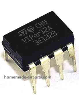
The proposed buck converter is an SMPS circuit using the IC VIPer12A from STMicroelectronics.
The circuit uses negligible number of external components yet is able to operate directly from mains AC input.
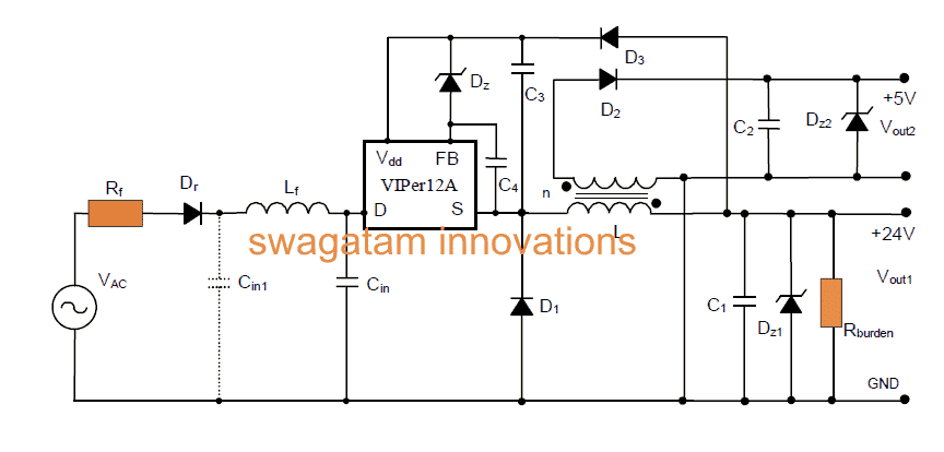
The Buck Converter Design
Looking at the given circuit diagram we see that the input stage incorporates a surge limiting resistor which quite acts like a fuse, a diode for rectifying the AC, and an LC filter network for further filtration of the DC riples.
The LC filter employed here ensures better DC stabilization and enhanced EMI response.
The capacitor Cin1 may be introduced for further reinforcing the EMI functionality.
The IC VIPer12A becomes the main PWM processor device which single handedly performs the entire buck conversion in the circuit.
Main Features
The main specifications of the configuration may be understood as follows:
- AC input voltage Vinac 80 - 285Vac
- Output current Iout 30mA
- Output current Iout 250mA
- Output voltage Vout1 +24±10%V
- Output voltage Vout2 +5V±5%
- Switching frequency 60 kHz
- Output Power ~ 1W
How it Works
The circuit facilitates two outputs, rhe 24V output is achieved through a buck converter configuration while the 5V output via fly back mode.
The feedback voltage to the IC is acquired from Vout1 for the required regulation of the output, this supply is also applied to the IC Vdd pin.
The above wiring becomes possible by using a single high voltage diode and just one capacitor, to be precise D1 and C3, making the connections and costing much simpler.
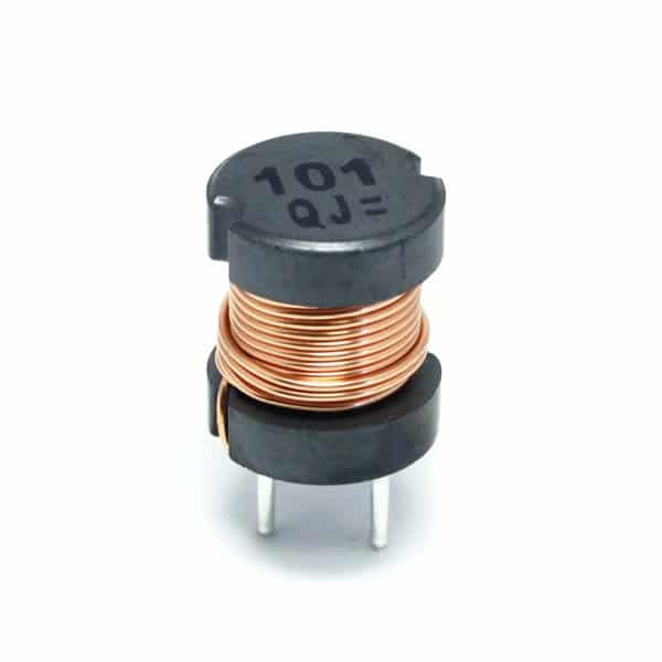
The employed inductor L consists of two windings which are coupled across with each other over a common ferrite core.
The winding are done through appropriate turn ratios, where N1 = 200 turns and N2 = 60 turns. Both these are wound over a PANASONIC ELC10D152E ferrite core material.

Zener diodes z1 and z2 are installed in order to safeguard the outputs against over voltages.
A dummy load resistor is fixed across Vout1 so that appropriate regulation can be executed over both the outputs during open load situations.
Though the addition of the above resistor affects the efficiency a bit, it superbly improves voltage regulation response of the circuit.
The rectifier diodes fixed at the output are fast response fast recovery types. D1 is a high voltage diode as it might be subjected to high reverse voltages delivered by the DC bus voltage...... D2 is a normal diode.
Parts List for the proposed simple SMPS buck converter circuit:
- Rr = 10W 1/2W
- Rf = 10KW 1/4W
- R(load) = 4.7kW 1/4W
- Cin = 4.7 μF, 450V Electrolytic Capacitor
- C1 = 33 μF, 50V Electrolytic Capacitor
- C2 = 100 μF, 16V Electrolytic Capacitor
- C3 = 1 μF, 25V Electrolytic Capacitor
- C4 = 22 nF Ceramic capacitor
- Dr = Diode 1N4007
- D1 = Diode BA159 (fast)
- D2 = Diode 1N4148 (fast)
- D3 = Diode 1N4004
- Dz = 22V Zener
- Dz1 = 27V Zener
- Dz2 = 5.6V Zener
- L 1 = 0.5 mH
- Lf = 470 μH Inductor
- IC1 = STMicroelectronics VIPer12ADIP
PCB Design and Component Layout of the above explained SMPS buck converter circuit using IC VIPer12A
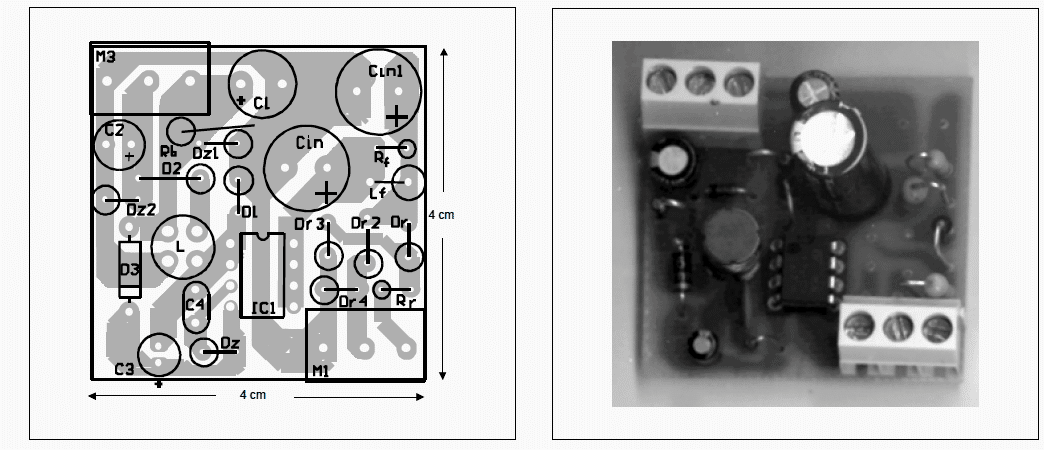
Complete Article can be found here