In this post I have explained how to make a simple 3 phase brushless DC motor driver circuit. The circuit employs the popular IRS2330 3-phase driver IC
The presented idea looks simple since most of the technicalities is taken care of efficiently by the IC itself, it's all about connecting the relevant pinouts with the few external supplementary components for the required implementations.
How BLDC with Hall Sensors Work
We know that all BLDC motors fundamentally incorporate Hall sensors attached with their stator assembly where these devices play a crucial rule in detecting and supplying the control circuit with the necessary data regarding the rotor magnet instantaneous positions with regard to the stator coil activation.
The info helps the control circuit to subsequently changeover the stator electromagnet activations sequentially such that the rotor constantly experiences a rotational torque and produces the intended rotational motion.
Therefore it seems that the hall effect sensors are the ones that become solely responsible for detecting and inducing the intended rotational motion in BLDC motors.
The control circuit connected with the hall sensors are in fact "blind" and respond entirely to the hall sensor signals in order to produce the required feed backs to the electromagnet coils.
The above fact actually makes the designing of a 3 phase BLDC motor controller pretty easy, the simplicity also becomes further aided with the easy availability of the universal 3 phase H bridge driver IC such as the IRS2330.
Studying the IC IRS2330 Specifications
The following discussion provides a comprehensive view on the designing of a 3 phase brushless BLDC motor driver circuit:

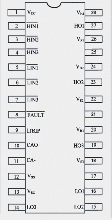
Pinout Details of the IC

The above shows the pinout diagram of the IC IRS2330 which simply needs to be connected to a set of a few external components for implementing the proposed BLDC controller circuit.

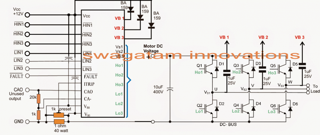
How to Configure the Full Bridge IC
In the above diagram we witness the method of connecting the IC pinouts with some external components wherein the right hand side IGBT stage shows a standard H bridge configuration using 6 IGBTs integrated with the appropriate pinouts of the IC.
The above integration concludes the output power stage for the BLDC controller circuit, the "load" indicates the BLDC 3 phase electromagnet coils, now its all about configuring the inputs HIN1/2/3 and LIN1/2/3 of the IC with the relevant hall sensor outputs.
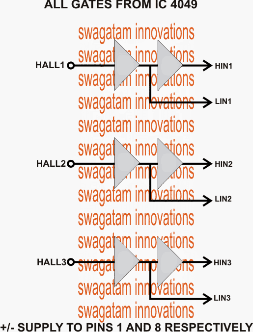
NOT gates for Sequencing the HIN, LIN Inputs

Before applying the hall sensor triggers to the driver IC inputs, it's required to be buffered through a couple of NOT gates as given in the diagram above.
Finally, the outputs of the NOT gates is integrated appropriately with the inputs of the IC IRS2330.
The negatives of all the hall sensors may be assumed to be grounded.
The second circuit which forms the main driver configuration for the proposed 3 phase brushless BLDC motor driver circuit, could be also seen having a current sensing stage across its lower left section.
The resistive divider may be appropriately dimensioned for enabling an over current protection and control over the connected BLDC motor.
For getting comprehensive details regarding the current sensing configuration and other intricacies of the whole design, one may refer to the following datasheet of the IC:
https://www.irf.com/product-info/datasheets/data/irs2330pbf.pdf
