A simple electronic ceiling fan regulator circuit using a triac and a diac is a common type of circuit which is used to control the speed of a ceiling fan.
This circuit basically works using phase control principle, in which the voltage supplied to the fan motor is varied by controlling the firing angle of the triac.
A diac is used to trigger the triac at a certain voltage level as determined by the setting of the potentiometer knob.
Let's break down the circuit step by step and explain the working of each component:
Triac is normally employed to work like a regulator device, which enables the adjustment of fan speed through phase-triggered power control principles.
This involves switching ON and switching OFF the triac once during each half-cycle of the mains power supply. The proportion of time the triac remains switched ON or OFF determines the average AC power supplied to the fan.
In order to eliminate radio frequency interference (RFI) issues caused by the rapid triggering of the triac, it is essential to incorporate a straightforward LC filter into the fan's power supply line.
There are a couple of basic methods widely used to achieve variable phase-delay triggering.
One method involves utilizing a diac in conjunction with an RC phase delay network, while another method employs a line-synchronized variable delay UJT trigger.
Simplest Fan Regulator Circuit
Below is an illustration demonstrating the practical setup of a diac-triggered simplest fan regulator circuit. In this fundamental configuration, R1-RV1-C1 form the variable phase delay components.

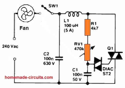
One drawback of this simple design is the presence of significant control hysteresis or backlash.
For instance, if the fan speed is reduced by increasing the RV1 value to 470k, it won't start again until RV1 is reduced to approximately 400k, and it will then operate at a relatively high speed level.
This "backlash" or the hysteresis issue is attributed to the diac partially discharging C1 each time the triac triggers.
Eliminating the Hysteresis Effect
To mitigate the "backlash" or the hysteresis effect in the aforementioned circuit, one can incorporate a 47 Ohm resistor in series with the diac, reducing its impact on discharging C1.
An even more effective solution is to employ the gate slaving circuit, as depicted in the following circuit
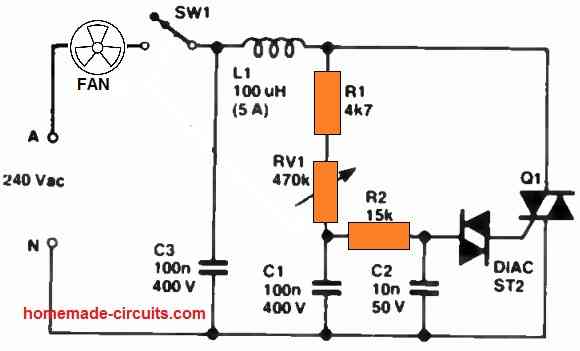
In this configuration, the diac is triggered from C2, which effectively replicates the phase delay voltage of C1. Additionally, R2 safeguards C1 against discharge when the diac triggers.
Hum Free Regulation by Eliminating RF Noise
In the above triac-based fan regulator circuits, the coil L1 and capacitor (C2, C3) combination acts as an RF filter to decrease electromagnetic interference (EMI) and create a hum free power supply to the fan.
This ensures smoother and more regulated functioning of the fan's speed control circuit.
This LC network aids in the reduction of electrical noise and disturbances, which can otherwise affect the functioning of the fan and other nearby electronic equipment such as radios, amplifiers, TV sets etc.
L1 Construction
Regarding the construction of L1, the core consists of a 30 mm long segment of a 9.6 mm diameter ferrite aerial rod.
Wind two layers of 20 turns in close proximity, focusing on the central 15 mm section of the core, using 0.63 mm diameter (22 B&S) enameled wire. Finish by covering it with two layers of plastic insulation tape.
Practical Design Without Filter Coil and Capacitor
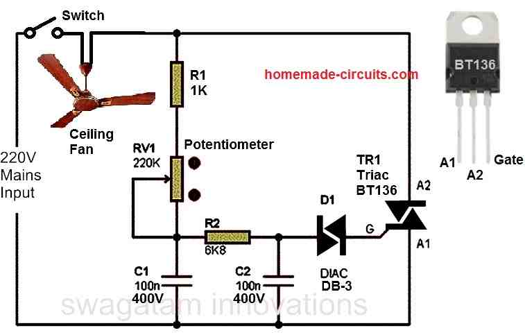
If the RF humming noise generation is not an issue to you, then you can ignore the filter coil and the capacitor elements and build the fan regulator circuit without these components as shown in the following diagram.
Step 1: Connecting the Resistor
Connect the 1/4 watt resistor in series with the potentiometer.
Step 2: Connecting the Diac
Connect one terminal of the diac to the junction of the potentiometer's middle terminal and one end terminal.
Connect the other terminal of the diac to one of the terminals of the triac (usually the gate terminal, denoted as "G"). This connection allows the diac to trigger the triac at a certain voltage level.
Step 3: Connecting the Triac
Connect the main terminals of the triac (A1 and A2) in series with the fan motor.
MT1 is connected to the phase/hot AC supply, and MT2 is connected to the load (fan motor). The gate terminal (G) of the triac is connected to the diac.
Step 4: Connecting the Potentiometer
Connect the variable terminal of the potentiometer to the common junction of the diac and the triac gate.
Connect one end of the potentiometer to the circuit's ground (usually the neutral line). Connect the other end of the potentiometer to the AC mains supply line (phase).
Step 5: Connecting the Diac control Capacitors
Connect the two capacitors C1 and C2 associated the diac, as indicated in the circuit diagram.
Step 6: Optional Filter Capacitor
To reduce noise and interference, we can connect a capacitor in parallel with the fan motor. The value of the capacitor depends on the specific application.
Components needed:
- 1K 1/4 watt 5% CFR = 1no
- 6.8K 1/4 watt 5% CFR = 1no
- 220K Potentiometer (variable resistor) = 1no
- 0.1uF / 400V Capacitor PPC = 2nos
- Triac (e.g., BT136) = 1no
- Diac (e.g., DB3) = 1no
Working Principle of Each Component
Potentiometer: The potentiometer works like a voltage divider. By adjusting the potentiometer, we change the voltage applied to the diac, which in turn controls the firing angle of the triac.
Diac: The diac is a bidirectional trigger device which conducts as soon as a certain voltage threshold is reached. It allows the triac to trigger and start conducting in both halves of the AC cycle.
Triac: The triac is a bidirectional semiconductor switch. When triggered by the diac, it allows current to flow through the fan motor.
By changing the firing angle of the triac, we control the amount of voltage and power delivered to the fan motor, thus controlling its speed.
Capacitors: The capacitor associated with the diac is responsible for introducing a phase shift. This phase shift determines when the diac is allowed to trigger during each AC half-cycle.
This phase shift in turn controls the firing angle of the triac, allowing us to control the power and thus the speed of the fan motor.
By adjusting the potentiometer, we are able to change the triggering point of the diac through the capacitors C1 and C2. This changes the phase angle of the triac conduction.
This phase control mechanism effectively controls the speed of the fan motor.
Caution
Remember that this circuit works with dangerous high-voltage AC power. Extreme precautions, insulation, and expertise are necessary while handling this circuit.
We strongly recommend consulting an experienced electrician or engineer while constructing and testing the above fan regulator circuit.
Understanding Triac Phase Control
Triac phase control using phase chopping is a method employed in the above circuit for regulating the speed of a ceiling fan.
In this approach, the triac is triggered to conduct only during a portion of each AC half-cycle, allowing us to control the effective voltage and power delivered to the fan motor. This, in turn, regulates the speed of the fan.
Let's dive into the details of how triac phase control using phase chopping works in the context of your ceiling fan regulator circuit:
AC Voltage and Triac Behavior:
AC voltage alternates between positive and negative half-cycles, with a frequency of 50 or 60 Hz.
A triac can be triggered to conduct in either direction when a certain gate voltage is applied to it. Once triggered, it remains conducting until the current drops below a certain threshold (holding current).
Basic Working:
The main aim of the triac phase chopping method is to control the firing angle at which the triac is triggered to conduct.
By triggering the triac at different points within each half-cycle, we are able to control the portion of the AC waveform that is delivered to the load (fan motor).
Phase Control and Speed Regulation:
During the periods the triac conducts early in a half-cycle (near the beginning of the AC waveform), it delivers more voltage and power to the load. This increases the fan motor speed.
Conversely, when the triac conducts later in the half-cycle (closer to the peak of the waveform), less voltage and power are delivered, resulting in a slower fan motor speed.
Potentiometer Adjustment:
The potentiometer in the circuit serves as a variable resistor, allowing you to adjust the triggering point of the diac.
As you adjust the potentiometer, you change the gate triggering angle of the triac, which controls when the triac starts conducting in each AC half-cycle.
Diac and Triggering:
The diac works like a triggering device for the triac. The diac fires and starts conducting only once a certain voltage threshold is reached.
Each time the diac conducts, it triggers the gate of the triac, allowing it to conduct and control the flow of current to the load (fan motor).
Variable Speed Control:
By adjusting the potentiometer, it is possible to change the phase angle at which the triac is triggered to conduct.
This causes a continuous adjustment of the fan motor speed due to the control of the effective voltage and power supplied to the motor.
Another 220V Ceiling Fan Regulator circuit Diagram and prototype images Submitted by a Dedicated user of this blog
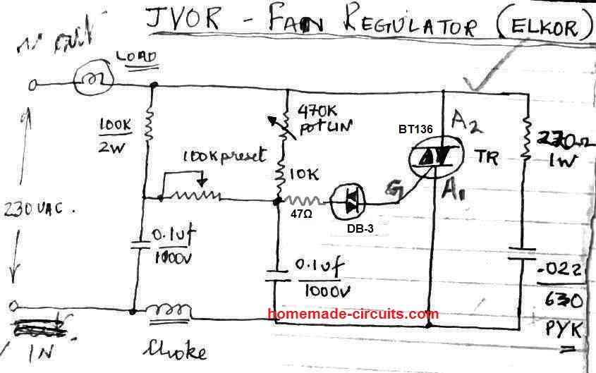
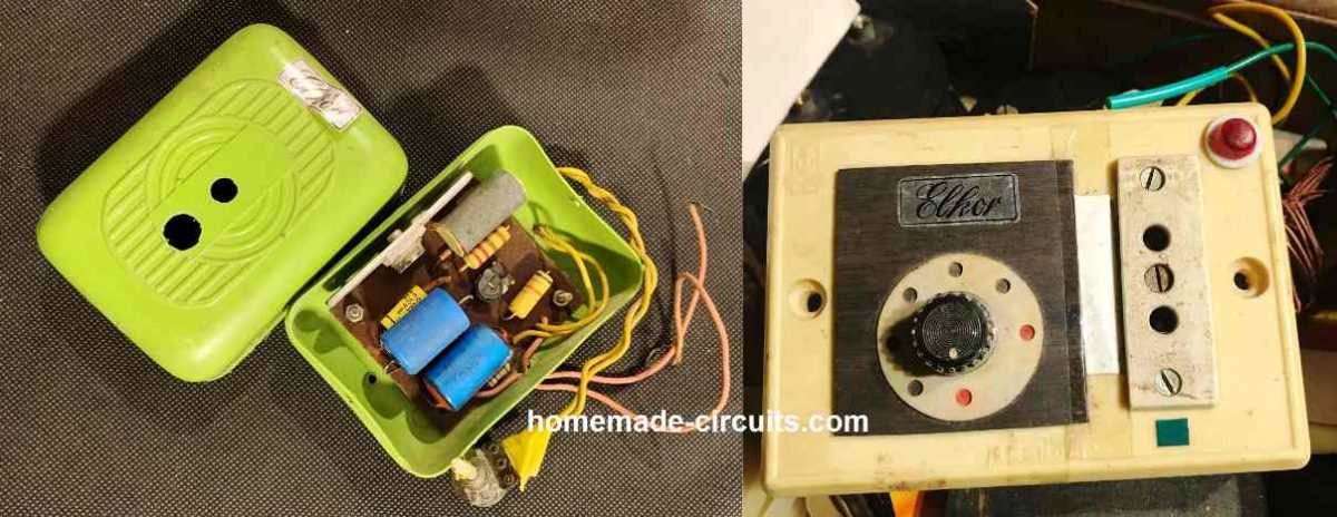
The choke is built using 5 meters of 30 SWG super enameled copper wire over a 1/2 inch diameter and 1 inch long ferrite core.
5 Step Fan Regulator Circuit
The above mentioned basic fan regulator circuit can also be adapted to achieve a 5 step control of the fan speed.
This adaptation involves substituting the potentiometer with a 5 way rotary switch connected to four fixed resistors, as depicted below:
The resistors might follow an increasing sequence such as: 220K, 150K, 120K, and 68K. Alternatively, you could experiment with different combinations within the range of 22K to 220K to find the most suitable configuration.
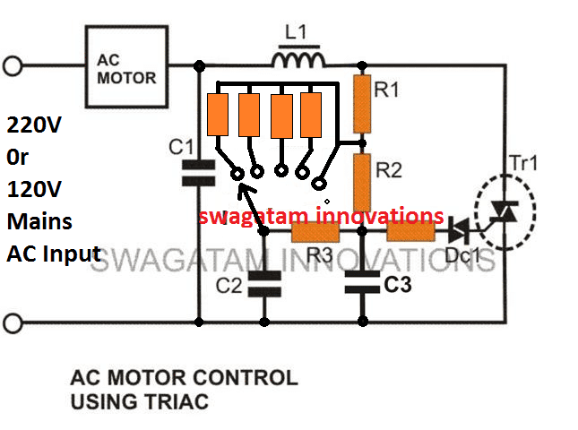
Parts List
- C1 = 0.1u/400V (optional)
- C2, C3 = 0.022/250V,
- R1 = 15K,
- R2 = 330K,
- R3 = 33K,
- R4 = 100 Ohms,
- The four stepped resistor can be as explained above.
- Diac = DB3,
- Triac = BT136
- L1 = 40uH (optional)
Conclusion
In summary, triac phase control which uses phase chopping is a technique which allows a smooth and continuous speed regulation of the fan motor.
This is basically implemented by varying the phase angle at which the triac conducts within each AC half-cycle. The potentiometer and the diac are used to control the triac gate triggering angle.
This in turn effectively controls the amount of power delivered to the fan motor, and thus, the speed of the ceiling fan.
This method offers a simple and efficient way for the user to adjust the fan's speed according to the required preferences.
Would you please explain more about using a resistor in series with DIAC, What value of resistor should I choose and why ?
Thanks in advance.
The value can be anything between 50 ohm and 100 ohm, to safeguard the diac from sudden high current spikes.
Bro if I remove 220k ohm potentiometer and place a 10k ohm potentiometer. what are the changes should i do in the circuit to make the circuit works.
Hello Guddu,
It is not possible to replace the 220k pot with 10k.
why is it that if I turn off the load on a certain adjustment of the setting of potentiometer , let’s say the potentiometer is of 470k and I turn off the load at 300k , then when I turn on the load the voltage is higher than what I have previously set during turning it of , why is it so .
Which circuit did you try? Please try the second design with two capacitors C1 and C2. Or you can try using a 220k pot and check the results.
Let me know how it goes.
I think it is the first one, the load here is a transformer , the transformer is operated with a triac such that it provides a variable voltage at the output, suppose I use the transformer at 13v then when I turn it off and again turn it on next time the output voltage is more than 14v but the thing is that both the times the input voltage are same that is 230v , is it the backlash phenomenon?
Yes, it could be a backlash problem.
I would suggest you to first verify the output results using an 220V incandescent bulb, and check whether the bulb glow is always the same or not when you turn it ON or off.
If you have problems try a 220k pot, or try the second circuit with two capacitors.
thank you so much for your reply , I had tried with the bulb and the bulb did not show any noticeable difference if I turn off and turn it on again , seems like only the transformer is affecting the system , is this behaviour normal ?
by the way I am using a normal fan regulator and I have just removed the triac bt136 and put there bta41 with a big heatsink , so now it can handle large loads ~40A , is is okay to use this type of modified circuit?
Thanks for updating the results.
If the bulb is getting affected, that means the dimmer circuit has no problems, and there’s no backlash. You can further confirm this by turning the pot to minimum…if the bulb filament shows some glow even at the minimum level, would indicate a correctly configured circuit.
To check the transformer behavior you can put a 100 watt incandescent lamp in series with 220V inpput and check whether the lamp glow changes or not with subsequent ON/OFF switching.
According to me a transformer behavior should be normal just like the bulb, because i have confirmed the results using transformer and for me it worked without any issues.
Yes, BTA41 should also work fine… for the diac please use a DB-3 diac.
thank you for your reply , yes I am using a db3 diac , the whole circuit is same just the triacs are exchanged , by the way I am using a inverter transformer that is used to charge the battery , since if I connect the transformer directly to main power supply , it will produce 18 volt at the output and I only require 12 to 13 volt maximum , so I have to use a dimmer at the input of the transformer to lower the output voltage , so only the output voltage is getting affected if I turn off and turn it on again without touching the potentiometer knob , I will check with a series bulb 100 watt and report you the results , again thanks a lot for clarifying my doubts . it help me positively .
No problem, let’s see what happens when a bulb is connected in series…all the best to you.