In many sensitive electronic circuits or loads, adjusting the current limit in its power supply could be one of the most crucial requirements for ensuring a fail proof safety for the various vulnerable devices.

A simple method of sensing current this using resistors has been discussed in this article.
Integrating a Current Sensor Stage
The current from a power supply is mostly rated at much higher levels than the required safe value for a particular circuit under test or under operation.
Some high grade power supplies may include an adjustable feature for controlling current at their outputs, however normally we don't see this facility within ordinary or homemade units.
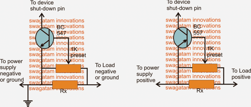
A simple variable current sensor configuration which could be built and used with sensitive circuits is shown below.
The resistor current sensor circuit utilizes just a single BJT and a few resistors.
Since most sensitive circuits may include an IC as the main active element, or a configuration having a shut down point somewhere within the circuit, this sensor module could be integrated with this input.
This will effectively implement the shutdown, and inhibit the circuit from functioning in case the current intake rises above the danger mark.
How it Works
The functioning of the adjustable current sensing module can be understood as given under:
For circuits which may have a ground shutdown feature, the circuit using the NPN device could be employed as shown in figure on left.
Here Rx is selected such that a potential difference of about 0.6V is developed when the amp consumption at the output or by the load tends to go above the marked danger threshold.
The 0.6V is the optimal conduction voltage level for the shown BC547 or any low power general purpose BJT, thus as soon as this level is reached, the BJT conducts and grounds the available shutdown pin, switching of the supply to the load instantaneously, and the process keeps repeating at the threshold making sure the consumption is not allowed to exceed the set level.
Calculating the Sensing Resistor
Rx may be selected with the help of the following Ohms law, and as per the circuit requirement:
R = 0.6/I
The preset at the base may be used for fine-tuning the cut off region.
Circuit Diagram

For Positive Shut-Down Operations
In circuits that demands shutdown from the positive line, the current sensor circuit at the right could be used.
This is exactly identical to its NPN counterpart with its functions, except the polarities which are configured to produce a positive drive for the shutdown pin connected across the collector of the BJT.
Now I have explained a few of the example circuits and ICs which facilitate a shut down feature within its allotted pinouts.
Integrating with IC 555
For IC 555, the reset pin#4, or the control pin#5 can be used as the shut down inputs, the NPN sensor above may be wired up here for the intended results.
Integrating with IC LM317/LM338/LM396
For LM317, LM338, LM350, LM396, the ADJ pin functions as the shutdown pin, again the NPN module would work with these devices for the desired current restrictions.
Integrating with IC 4017/IC4060
ICs such as 4060, 4017 may be stopped from functioning by applying a positive reset voltage at their pin#12 and pin#13 respectively. Thus for these examples the current sensor with the PNP device will suit perfectly for the required amp control.
Integrating with IC SG3525/IRS2453
Other examples include IC SG3524/5 = pin#10, positive trigger shutdown.
IRS2453 full bridge driver = pin#5, latched shutdown, positive trigger (2V)
For opamp protection circuits, the input pin which may be responsible for inhibiting the power device at its output may be targeted as the shut down pin and appropriately wired up with either of the above current sensing modules.

Have Questions? Please Comment below to Solve your Queries! Comments must be Related to the above Topic!!