The digital time clock explained here is a circuit which most electronic amateurs would love to make.
You might have heard about digital clocks made from clock ICs such as the popular LM8361, MM5387 etc but these ICs could be today quite obsolete and/or complex to build.
Circuit Operation
The present design is much easier and no less than their above mentioned counterparts in terms of feature and specs. Moreover there's one added advantage included in this digital clock circuit, it's Duplex LED display model, which helps to reduce the number of connections and links across the IC1 (LM8560) and the LED display, allowing the configuration to be much simpler.
Now I have explained how the proposed digital clock circuit functions:
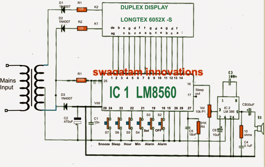
As may be witnessed in the given diagram the heart of the circuit is formed by the IC1 (LM8560),
which is assigned with the following outputs terminals:
1. The output for driving the display Duplex Model numbers (pin 1-14)
2. The output for generating an alarm signal at pin 16.
3. The output option which may be utilized for controlling external electrical appliances through an in-built automatic timer.
The parts R1, C1 are included in the circuit in order to facilitate an input 50 Hz clock to pin25 of the IC.
The diodes D1, D2 are positioned as rectifiers to function as signal generators to the cathode of display number for generating an alternating working of the display illumination in relation with the input of IC1.
The alarm signal from pin 16 of IC1, is hooked up with a potentiometer P1(Volume) and further integrated with pin 3 of IC2 (LM386) which forms the amplifier stage for driving a loudspeaker during alarm activations.
The P1 is included in order to provide a fine tuning option for the alarm signal volume. Additionally the signal from the "sleep" pinout from pin 17 may be used for controlling any other desired trigger circuit.
How to set the time in this digital clock
1. S6 is used to set hours.
2. S4 is used to set minutes.
To set the alarm time the following switches may be used:
1. S3 to hold down the time
2. S5 to set hours for the alarm.
3. S4 to set minutes for the alarmm.
Once the above mentioned time limit through S4/S5 elapses, the alarm may start ringing which may be stopped by pressing switch S2 or in fact any other switch out of the given ones.
The following switches may be used for controlling an external appliance from the clock triggers.
1. Initially you would need to keep switch S6 pressed
2. Next press S4 to set minutes.
3. Press switch S5 to set hours.
The output signal for the above explained ON/OFF control of appliances may be acquired from pin17 of the IC.
Using time dilation alarm to repeat alarm.
In order to use this function if in case we want to Repeat alarm or to extended for another nine minutes, you may want to press switch S7.
Circuit Diagram