

The simple gate open and close controller circuit is designed to operate the gate through a couple of push buttons manually, it can be also modified for implementing the activation through a remote control.
How it Works
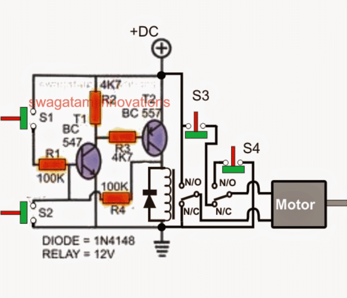
Referring to the shown, simple gate open, close controller circuit below, we can witness a rather straightforward configuration, essentially comprising of a transistor latch stage, a DPDT relay stage and a few push to ON/OFF switches.
The push switches S3/S4 play an important role in the circuit and ensure that the motor never gets overloaded when it reaches its end limits.
The images of the switches which are ideally suited to this application is shown just below the circuit diagram. These are quite popular and can be easily procured from any relevant electronic retailer.
Circuit Diagram

Parts List
- Resistors are all 1/4 watt 5%
- R1, R4 = 100k
- R2, R3 = 4.7k or 10k both
- Relay diode = 1N4007
- T1 = Transistor BC547
- T2 = Transistor BC557
- Relay = 12V DPDT
- S1, S2 = Push button switches
- S3, S4 = push to OFF as shown below
Set Reset Push Switches

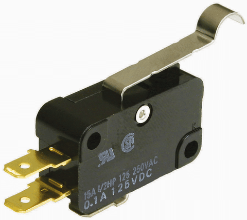
The above Switch is to be used for S3, S4
Transistor T1, T2 along with the associated parts form a reliable latch circuit, S1 and S2 are ordinary push-to-ON switches, where S1 is rigged as the "set" button, and S2 as the reset button, which work for opening and closing the connected respectively.
S3 and S4 are fixed across the end travel points of the gate mechanism, such that the gate pushes these OFF each time it reaches the end destinations, and releases while it moves away from the destination or while the gate is in the course of its travel.
Assuming the gate to be in the closed position initially, we can expect the following scenario:
Operational Steps
S3 in depressed position by the gate and therefore in the cut-off mode.
S4 in released position and therefore contacts closed and switched ON.
The latch circuit switched OFF, and so is the DPDT relay.
The DPDT relay contacts are at the N/C points.
With the above situation, pressing S1 initiates the following course of actions:
T1 and T2 instantly latches, actuating the DPDT relay in the N/O positions.
The motor now begins running through the supply via the S4 and the DPDT relay N/O contact supply in the set direction, enabling the gate to operate with an opening action. This also releases S3 in the process.
As soon as the gate reaches the end limit or the end destination, and opening up fully, it presses S4 cutting off the supply to the motor. The gate now halts and comes to a stand still.
How Motor Rotation is Flipped
This position can be maintained infinitely, until S2 is pressed, which breaks the T1/T2 latch, and deactivates the DPDT relay forcing its contacts to move across the N/C points.
This immediately flips the motor polarity causing the motor to rotate in the opposite direction and enables the gate to reverse back to its closing position. While in this mode the motor gets its power from S3, but only until it reaches its earlier destination, ie. in the closed position, when it presses S3, cutting off power to the motor and yet again disabling the motor.
The gate maintains this position until S1 is pressed yet again for initiating the opening action of the gate...thus the open/close operation of the gate is simply implemented by actuating S1 and S2 switches manually.
In order to execute a remote controlled open, close action of the gate, S1 and S2 could be replaced with momentary relay contacts, and the relays operated through the receiver unit of the remote control.
Any standard 400 MHz RF, 2-relay type remote control modules could be used for the stated remote open, close control of the gate.