In this post I have explained 2 easy to build induction heater circuits which work with high frequency magnetic induction principles for generating substantial magnitude of heat over a small specified radius.
The discussed induction cooker circuits are truly simple and uses just a few active and passive ordinary components for the required actions.
Update: You may also want to learn how to design your own customized induction heater cooktop:
Designing an Induction Heater Circuit - Tutorial
Induction Heater Working Principle
An induction heater is a device that uses a high frequency magnetic field to heat up an iron load or any ferromagnetic metal through eddy current.
During this process electrons inside iron are unable to move as fast as the frequency, and this gives rise to a reverse current in the metal termed as eddy current. This development of high eddy current ultimately causes the iron to heat up.
The generated heat is proportional to current2 x resistance of the metal. Since the load metal is supposed to be made up of iron, we consider the resistance R for the metal iron.
Heat = I2 x R (Iron)
Resistivity of Iron is: 97 nΩ·m
The above heat is also directly proportional to the induced frequency and that's why ordinary iron stamped transformers are not used in high frequency switching applications, instead ferrite materials are used as cores.
However here the above drawback is exploited for acquiring heat from high frequency magnetic induction.
Referring to the proposed induction heater circuits below, we find the concept utilizing the ZVS or zero voltage switching technology for the required triggering of the MOSFETs.
The technology ensures minimum heating of the devices making the operation very efficient and effective.
Further to add, the circuit being self resonant by nature automatically gets sets at the resonant frequency of the attached coil and capacitor quite identical to a tank circuit.
Using Royer Oscillator
The circuit fundamentally makes use of a Royer oscillator which is marked by simplicity and self-resonant operating principle.
The functioning of the circuit could be understood with the following points:
- When power is switched ON, positive current begins flowing from the two halves of the work coil towards the drains of the mosfets.
- At the same the supply voltage also reaches the gates of the mosfets turning them ON.
- However due to the fact that no two mosfets or any electronic devices can have exactly similar conducting specifications, both mosfets do not turn on together, rather one of them turns ON first.
- Let's imagine T1 turns ON first. When this happens, due to heavy current flowing through T1, its drain voltage tends to drop to zero, which in turn sucks out the gate voltage of the other mosfet T2 via the attached schottky diode.
- Here, it may seem that T1 might continue to conduct and destroy itself.
- However, this is the moment when the L1C1 tank circuit comes into action and plays a crucial part. The sudden conduction of T1 causes a sine pulse to spike and collapse at the drain of T2. When the sine pulse collapses, it dries down the gate voltage of T1, and shuts it down. This results in a rise in voltage at the drain of T1, which allows a gate voltage to restore for T2. Now, its the turn of T2 to conduct, T2 now conducts, triggering a similar kind of repetition that occurred for T1.
- This cycle now continues rapidly causing the circuit to oscillate at the resonant frequency of the LC tank circuit. The resonance automatically adjusts to an optimal point depending on how well the LC values are matched.
However the main downside of the design is that it employs a center tapped coil as the transformer, which makes the winding implementation a bit trickier. However the center tap allows an efficient push pull effect over the coil through just a couple of active devices such as mosfets.
As can be seen, there are fast recovery or high speed switching diodes connected across the gate/source of each mosfet.
These diodes perform the important function of discharging the gate capacitance of the respective mosfets during their non-conducting states thereby making the switching operation snappy and quick.
How ZVS Works
As I have explained earlier, this induction heater circuit works using the ZVS technology.
ZVS stands for zero voltage switching, meaning, the mosfets in the circuit switch ON when they have minimum or amount of current or zero current at their drains, we have already learned this from the above explanation.
This actually helps the mosfets to switch ON safely and thus this feature becomes very advantageous for the devices.
This feature could be compared with the zero crossing conduction for triacs in AC mains circuits.
Due to this property the mosfets in ZVS self resonant circuits such as this require much smaller heatsinks and can work even with massive loads upto 1 kva.
Being resonant by nature, the frequency of the circuit is directly dependent on the inductance of the work coil L1 and the capacitor C1.
The Frequency could be calculated using the following formula:
f = 1 / ( 2π * √[L * C] )
Where f is the frequency, calculated in Hertz
L is the inductance of the Main Heating Coil L1, presented in Henries
and C is the capacitance of the capacitor C1 in Farads
The MOSFETs
You can use IRF540 as the mosfets which are rated at good 110V, 33amps. Heatsinks could be used for them, although the heat generated is not to any worrying level, yet still it's better to reinforce them on heat absorbing metals. However any other appropriately rated N channel MOSFETs can be used, there are no specific restrictions for this.
The inductor or inductors associated with the main heater coil (work coil) is a kind of choke that helps eliminating any possible entry of the high frequency content into the power supply and also for restricting the current to safe limits.
The value of this inductor should be much higher compared to the work coil. A 2mH is generally quite enough for the purpose. However it must be built using high gauge wires for facilitating a high current range through it safely.
The Tank Circuit
C1 and L1 constitute the tank circuit here for the intended high resonant frequency latching. Again these too musts be rated to withstand high magnitudes of current and heat.
Here we can see the incorporation of a 330nF/400V metalized PP capacitors.
1) Powerful Induction Heater using a Mazzilli Driver Concept
The first design I have explained below is a highly efficient ZVS induction concept based on the popular Mazilli driver theory.
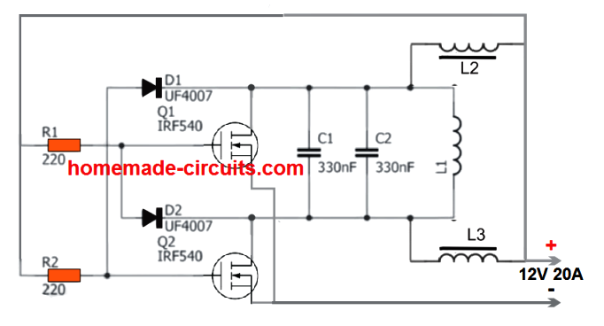
It uses a single work coil and a two current limiter coils. The configuration avoids the need of a center tap from the main work coil thus making the system extremely effective and rapid heating of load with formidable dimensions. The heating coil heats the load through a full bridge push pull action
The module is actually available online and can be easily bought at a very reasonable cost.
The circuit diagram for this design can be seen below:

The original diagram can be witnessed in the following image:
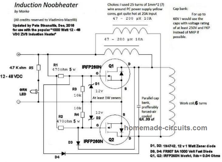
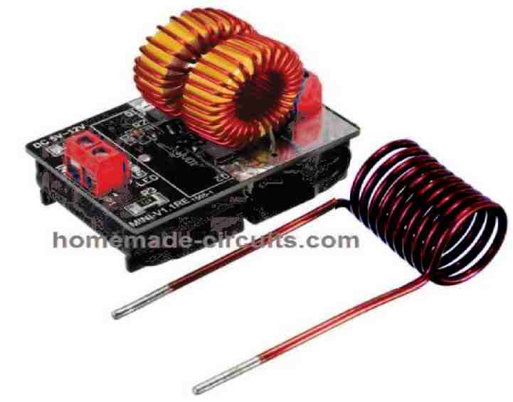
The working principle is the same ZVS technology, using two high power MOSFETs. The supply input can be anything between 5V and 12V, and current from 5 amps to 20 amps depending on the load used.
Power Output
The power output from the above design can be as high as 1200 watts, when the input voltage is raised up to 48V, and current up to 25 amps.
At this level the heat generated from the work coil can be high enough to melt a 1 cm thick bolt within a minute.
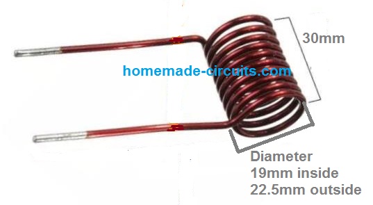
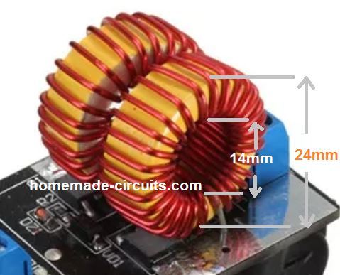
Work Coil Dimensions
Video Demo
2) Induction Heater using a Center Tap Work Coil
This second concept is also a ZVS induction heater, but uses a center bifurcation for the work coil, which may be slightly less efficient compared to the previous design. The L1, which is the most crucial element of the whole circuit. It must be built using extremely thick copper wires so that it sustains the high temperatures during the induction operations.
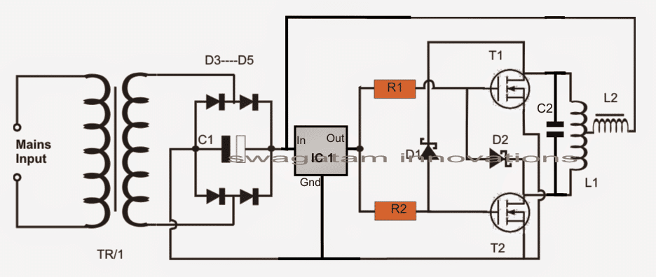
The capacitor as discussed above must be ideally connected as close as possible to the L1 terminals. his is important for sustaining the resonant frequency at the specified 200kHz frequency.
Primary Work Coil Specifications
For the induction heater coil L1, many 1mm copper wire may be wound in parallel or in bifilar manner in order to dissipate current more effectively causing lower heat generation in the coil.
Even after this the coil could be subjected to extreme heats, and could get deformed due to it therefore an alternative method of winding it may be tried.
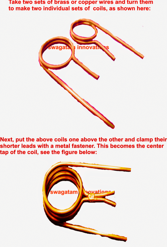
In this method we wind it in the form of two separate coils joined at the center for acquiring the required center tap.
In this method lesser turns may be tried for reducing the impedance of the coil and in turn increase its current handling capability.
The capacitance for this arrangement may be in contrast increased in order to pull down the resonant frequency proportionately.
Tank Capacitors:
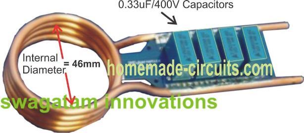
In all 330nF x 6 could be used for acquiring a net 2uF capacitance approximately.
How to Attach Capacitor to the Induction Work Coil
The following image shows the precise method of attaching the capacitors in parallel with the end termianals of the copper coil, preferably through a well dimensioned PCB.
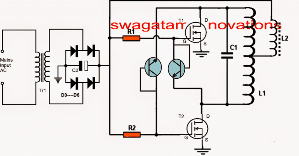
Parts list for the above induction heater circuit or induction hot plate circuit
- R1, R2 = 330 ohms 1/2 watt
- D1, D2 = FR107 or BA159
- T1, T2 = IRF540
- C1 = 10,000uF/25V
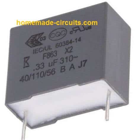
- C2 = 2uF/400V made by attaching the below shown 6nos 330nF/400V caps in parallel
- D3----D6 = 25 amp diodes
- IC1 = 7812
- L1 = 2mm brass pipe wound as shown in the following pics, the diameter can be anywhere near 30mm (internal diameter of the coils)
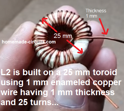
- L2 = 2mH choke made by winding 2mm magnet wire on any suitable ferrite rod
- TR1 = 0-15V/20amps
- POWER SUPPLY: Use regulated 15V 20 amp DC power supply.
Using BC547 transistors in place of high speed diodes
In the above induction heater circuit diagram we can see the MOSFETs gates consisting of fast recovery diodes, which might be difficult to obtain in some parts of the country.
A simple alternative to this may be in the form of BC547 transistors connected instead of the diodes as shown in the following diagarm.
The transistors would perform the same function as the diodes since the BC547 can operate well around 1Mhz frequencies.
Another Simple DIY Design
The following schematic shows another simple design, similar to the above, which can be constructed quickly at home for implementing a personal induction heating system.
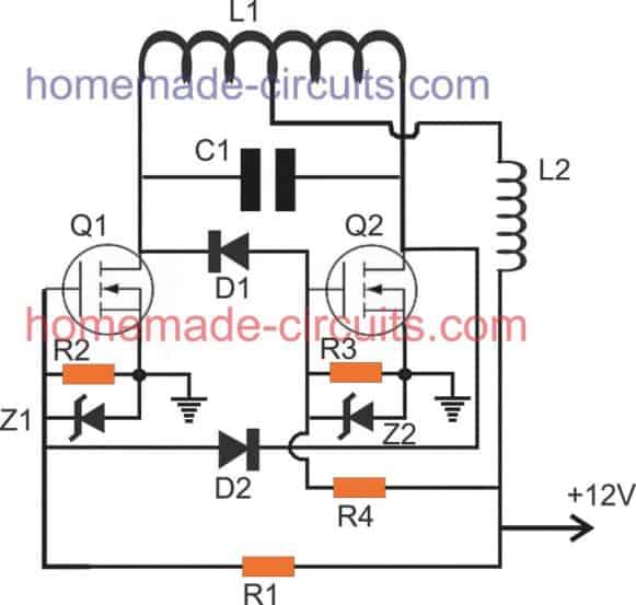
Parts List
- R1, R4 = 1K 1/4 watt MFR 1%
- R2, R3 = 10K 1/4 watt MFR 1%
- D1, D2 = BA159 or FR107
- Z1, Z2 = 12V, 1/2 watt zener diodes
- Q1, Q2 = IRFZ44n mosfet on heatsink
- C1 = 0.33uF/400V or 3 nos 0.1uF/400V in parallel
- L1, L2, as shown in the following images:
- L2 is salvaged from any old ATX computer power supply.
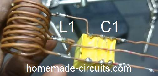
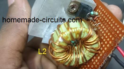
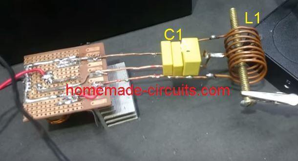
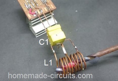
How L2 is Built
Modifying into a Hot Plate Cookware
The above sections helped us to learn a simple induction heater circuit using a spring like coil, however this coil cannot be used for cooking food, and needs some serious modifications.
The following section of the article explains, how the above idea can be modified and used like a simple small induction cookware heater circuit or an induction kadai circuit.
The design is a low tech, low power design, and may not be on par with the conventional units. The circuit was requested by Mr. Dipesh Gupta
Technical Specifications
Sir,
I have read ur article Simple Induction Heater Circuit - Hot Plate Cooker Circuit And was very happy to find that there are people ready to help youngsters like us to do something ....
Sir I am trying to understand the working and trying to develop an induction kadai for myself ... Sir please help me understanding the designing as I m nt so good in electronics
I want to develop an induction to heat up a kadai of dia 20 inch with 10khz frequency at a very low cost !!!
I saw your diagrams and article but was a bit confused about
- 1. Transformer used
- 2. How to make L2
- 3. And any other changes in the circuit for 10 to 20 kHz frequency with 25ams current
Please help me sir as soon as possible ..It will be help full if u could provide with the exact components detail needed .. PlzzAnd lastly u had mentioned to use POWER SUPPLY: Use regulated 15V 20 amp DC power supply. Where is it used ....
Thanks
Dipesh gupta
The Design
The proposed induction kadai circuit design presented here is just for experimental purpose and may not serve like the conventional units. It may be used for making a cup of tea or cooking an omelet quickly and nothing more should be expected.
The referred circuit was originally designed for heating iron rod like objects such as a bolt head. a screwdriver metal etc, however with some modification the same circuit can be applied for heating metal pans or vessels with convex base like a "kadai".
For implementing the above, the original circuit wouldn't need any modification, except the main working coil which will need to be tweaked a bit to form a flat spiral instead of the spring like arrangement.
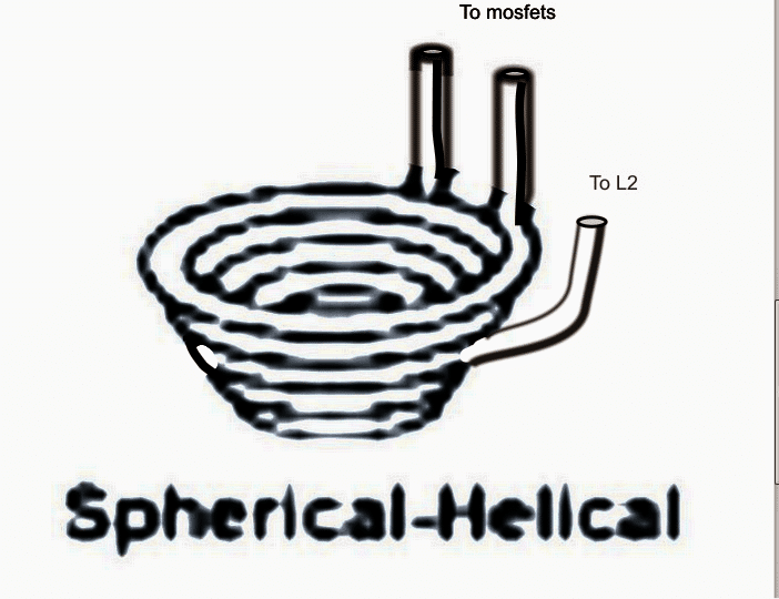
As an example, in order to convert the design into an induction cookware so that it supports vessels having a convex bottom such as a kadai, the coil must be fabricated into a spherical-helical shape as given in the figure below :
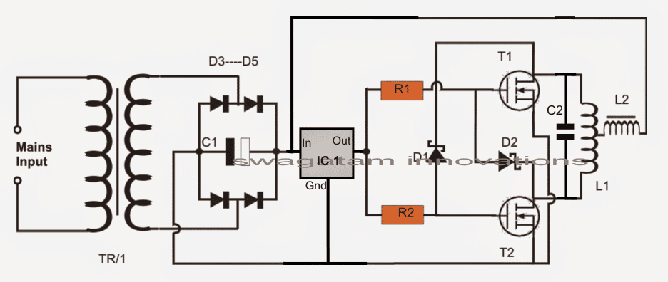
The schematic would be the same as explained in my above sevction, which is basically a Royer based design, as shown here:
Designing the Helical Work Coil
L1 is made by using 5 to 6 turns of 8mm copper tube into a spherical-helical shape as shown above in order to accommodate a small steel bowl in the middle.
The coil may be also compressed flat into a spiral form if a small steel pan is intended to be used as the cookware as shown below:


Designing the Current Limiter Coil
L2 may be built by winding a 3mm thick super enameled copper wire over a thick ferrite rod, the number of turns must be experimented until a 2mH value is achieved across its terminals.
TR1 could be a 20V 30amp transformer or an SMPS power supply.
The actual induction heater circuit is quite basic with its design and does not need much of an explanation, the few things that needs to be taken care of are as follows:
The resonance capacitor must be relatively closer to the main working coil L1 and should be made by connecting around 10nos of 0.22uF/400V in parallel. The capacitors must be strictly non-polar and metalized polyester type.
Although the design may look quite straightforward, finding the center tap within the spirally wound design could pose some headache because a spiral coil would have an unsymmetrical layout making it difficult to locate the exact center tap for the circuit.
It could be done by some trial and error or by using an LC meter.
A wrongly located center tap could force the circuit to function abnormally or producing unequal heating of the mosfets, or the entire circuit may just fail to oscillate under a worst situation.
Reference: Wikipedia

Hi Swagatam says
I need a wire diameter of ” l1″ and the number of wire turns, and I also need to measure the diameter of the circle
I need wire diameter “l2” and number of rolls on ferrite rod
If the ferrite is shaped like a diameter ring, I need the inner diameter and the outer diameter, and is any measurement suitable?
Thank you
Rami, all the details required by you are given in the 4rth and 5th diagrams.
Wire thickness of L2, L3 can be 1 mm, and for the work coil L1 wire thickness can be above 2 mm.
thank you for your reply
I mean the scheme that uses a file that has a junction point in the middle
In addition to the number of turns per one – and measure the diameter of each roll
I have a final request to refer me to a good design link on your page for the Moisture Determination Department, in which you do not use Urdu
I apologize for pressing and thank you
L1, L2 details are already given in the parts list. For moisture meter you can read the following article:
https://www.homemade-circuits.com/mini-weather-station-using-arduino/
I am talking about this design…..2) Induction Heater using a Center Tap Work Coil
Can the transistor T1, T2 = IRF540 be replaced with IRF640N
It won’t work efficiently.
hello dear sir i built the first one successfully and paralleled three MOSFETs on each side and increased the number of capacitors to increase the
work coil power,to melt gold brass and copper i put a crucible that is built from graphite that is a kind of the great ferromagnetic that resulted to thawing
and melting the three metals through overheating of the crucible and the heat transferred to the metals,and by pouring and flowing water into the coil pipe
of course without salt that is distilled water,i have a few questions that i am very confused and could not figure out
the first is how this circuit discover that it has to equalize the L resistor and the C capacitor by varying the frequency in order to minimize current
and follow it maximum power,,the second one this is that whether by placing Ferrite on the outer side of the cylindrical coil can the
furnace power be increased by reducing the eruption and magnetic field dispersion and and follow it raising inductance,,
the third one is that how i can melt steel and iron of course i have to consider removing graphite crucible and instead of the i must use an ceramic
crucible without ferromagnetic elements
Thank you Sedigh, I am glad you could upgrade the first circuit into a high power induction heater. To limit current or reduce current you can try increasing the number of turns of L2 and L3…the resonance cannot be decreased since the design is a self resonating circuit.
The first design is the recommended one and I think you should proceed working with this design
thanks a lot for your quick reply dear sir but i wanted to know “”whether exist a few ferrite around the work coil could increase the power of the furnace ??””and consequently results a decrease of current due to removing eruption dispersion and help to boost transferring whole of the magnetic field to inside coil for producing eddy current as a result raising efficiency and decrease consumption current
Hi Sedigh, I don’t think that would work, the only way to increase heat and reduce current is by matching the resonance….no other method might work other than resonance.
Can I use a triac light dimmer circuit with a bridge rectifier for powering this induction heater.
No, you have to use a 12V DC as described in the schematic
Can I use a triac based power supply by using bta41 triac for 30v 40amp. Also I don’t have large ferrite torroid nor a rod. So can I use 2 instead of 1 connected in series.
No, you must do everything exactly as specified in the diagrams.
D Ramesh ,
I tried earlier royer oscillator carrying irfp260 n mosfets when 35mm curcible of graphite loaded 15 percent in side coil both of mosfet gate leg deep burnt ,operating under 24 dc before working good with small knife red hot , secondly i brought out the mosfets seperately into an al sink big and both back sinks electrical insulated and fixed in aluminum ( old arc welding mch sink i used) is this wrong .any how if this melting circuit for is available give me details
dear sir please mail me an induction circuit for gold melting .
D Ramesh
Dear Ramesh, you can use the circuit explained above, and modify the iron nail into a C channel shaped iron cavity, and then melt gold inside this channel.
THANK YOU SIR I THINK FAN COOLING IS ESSENTIAL.
Good afternoon friend greetings, in advance congratulations on your contribution .. I would like to know more or less how much is the capacity of the working coil with the metal already inside the coil… Since my circuit does not oscillate
Hi, the metal inside the coil should be strictly an iron metal, and it can be of any thickness. You can actually buy one ready made unit and see how it is built to replicate it again. The capacity of the working coil is around 500 watts.
If I have to heat a metal pipe of about 25 cm in length and and 1cm diameter,will this design be good enough??Also can u make a video of explanation of the circuit because I didnt understand fully well
The portion of the pipe within the coil will heat up quickly, but the remaining portion of the pipe may take time to heat. The pipe must be ferromagnetic
Please specify what you did not understand, I’ll try to help!
Nice article for understanding induction heat, Thanks for this presentation,
Thanks Raja, Glad you liked it!
Dear master
If I want to make a more powerful induction heater that can heat a voluminous iron rod in a high temperature what I must to do? Is it possible making such a heater? So what would be the circuit?
Hi Mans, for powerful heater you will have to upgrade the mosfets with higher rating, and use thicker tubes or wires for all the coils. Similarly the capacitors will also need to be rated with higher current values.
Can i make flyback driver and tesla coil by it?
sorry I have no idea about it
Nice, Can I use two solar panel rated 10 Amp each as DC power source
yes definitely you can try…
Sir i made zvs circuit using 70t036h 60 amp mosfet and used 12v 20 ampere powersupply but my mosfets are getting really hot i don’t know why. but it does work and i dont think it will work for more than 5 secs as it will fry entire circuit.
I used 560 ohm resistor instead of 330 ohm for gate driving and didn’t used lm7812 since i am using constant voltage
LM324,
for the above circuits, mosfet will typically heat up due to the following reasons:
high gate resistance or high gate voltage above 15V
High collector current due to lack of resonance.
L2 and L1 not correctly designed.
I think you should try reducing the gate resistance to 100 ohms or even lower.
Make sure the L2 inductance is adjusted to the specified. value.
I hope you have used fast recovery diodes at the gates of the mosfets?
make sure to use large heatsinks on the mosfets.
Use a variable voltage power supply and try tweaking the voltage input and check which combinations produces the best resonance, using that as the reference keep adjusting the voltage and the L1/L2 turns until the optimal value is determined at the maximum voltage range.
Sir my mosfets has 9m ohm. is this the reason for heating
. If yes how can i solve heating issue
No that cannot the cause, I have already explained the main reasons in my earlier comment please go through them and solve it step wise…
Sir i used 5 pairs on 13007 transistor instead of the mosfet you said in the diagram and for the inductor i made 10 wound of coil around ferrite transformer and the circuit worked when i connected it to variable power supply made using lm317t but when i connected to my 12v 5 amp battery it didn’t worked. Sir can you please help me to make this work
Hi Loki, what are trying to make?? If you are trying to make an induction heater then your set up will not work, you will have to do everything exactly as recommended in the above article and diagrams.
Sir thanks for the quick reply
then i will only replace the mosfet with 13007 and the other components exactly in the diagram. will this work
Thanks
Loki, if you do it with proper understanding using all the mentioned parameters correctly then it will definitely work.
remember to use fast recovery diodes at the gates of the mosfets
Can i ise fr15 diode
yes it will do….
Sir, Thanks for great design. I want to make 250 watt induction hot plate. what changes I would have to make in this circuit. What can be the design of heating coil?
Thanks Ravindra,
I have explained the details in the following tutorial, you can read it customize the design as per your preferred requirement.
https://www.homemade-circuits.com/designing-induction-heater-circuit/
good
Hello sir… can i use for coocking perpouse ???
yes you can, but you will have to modify the coil into a pancake style
Ok thank you sir
Mr. swagatam.can this tool to heat 4 liters of water in the pipe 4 “?? Thank you
Febry, if the water is passed very slowly, then probably it will work….the copper coil itself could be used as the pipe….
Dear sir… if i can get help from you having the Induction heater schematic that does not use Mosfets and also the Inverter 500watts+ it will help a lot… i have a lot of problems laying hands on mosfets in my location.
Dear Deogratia, you can try the following concept and see if it works fr you
https://www.homemade-circuits.com/2017/01/high-current-wireless-battery-charger.html
it is a wireless electricity transmitter but the same an be implemented for induction heating
i also came accross this project on your wall… please i will like to ask if this is a 500watts 220vac inverter that can be use for homes.
here is the link below.
3.bp.blogspot.com/-oyXtDjDRk84/VGB2oRtPPhI/AAAAAAAAIjE/irHRQ5SPagI/s1600/48%2BV%2Binverter%2Bcircuit.png
i wait your reply and thanks for the great stuff's you have on your page.
No it cannot be used for all home appliances since it is a square wave type…but as far as power output is concerned it will be able to provide 500 watt easily
Thanks for the feedback, i will be having problems finding parts like mosfet transistors in my location where i live, so please can you help me with a easy sine wave inverter schematic that can deliver 500+ watts just like the one i talked about? thanks for your understandings.
a sine wave schematic that works with the same tip35 and tip122 that can deliver +500watts is what i am seeking for my project…i see it's like sine wave works with nearly every equipment
You can try the first circuit from this article
https://www.homemade-circuits.com/2013/10/pure-sine-wave-inverter-circuit-using.html
replace the mosfet with a TIP122/TIP35 pairs on both channels
Dear sir.
How many turns should L1 and L2 be? i wish to use this for my cloth dryer project.
please i need your help on that.
Thanks.
Dear Deogratia, please go through the article explanation, diagrams, and the comments, I have already explained L1/L2 details elaborately
Dear sir,
I need your help . I’m using preethi induction stove. My problem (2uF 275VAC Class X2 Box Type Capacitor) capacitor was Busted but my area only available in (2.2uF 275VAC Class X2 Box Type Capacitor) may I use 2.2uF this capacitor
thank you
Dear Satish, according to me it should work, no harm in trying it out….
Sir,
. I have done first circuit by considering all the parameters you have told , it took 5 ferrite rod (each 20cm in length) by winding 1.5 mm copper wire to get 2mH by verifying on LCR meter , and even exat value 6 capacitor connected across parallel as mentioned in the article by giving 2uF , and finaly connected to a battery (12v/ 80ah) no sooner I cgave power supply one of the mosphet reches to a verry high temperature and blow off and other remain cool and this happens within 5-6 seconds
I tried 4times the same circuit , evey time mospfet blow off , ialso used heatsinks
Adithya, why did you use 5 ferrite rods? The coil must be wound over a single ferrite rod…if you do anything randomly as per your wish, then you will keep blowing the devices.
which diode did you use for the mosfet gates
did you connect the LC tank as indicated in the 3rd diagram from top??
the L2 must a be neatly wound inductor over a single ferrite rod, the shape does not matter.
secondly your circuit must begin self resonating, and this will strictly depnd on the value of the LC tank circuit and the voltgae.
you must begin with a low volatge may be around 6V and then gradually increase it until you have the best possible results.
while doing this you must have an ammeter connected i series with the input supply, and you just have a iron rod inserted through the work coil. This iron could be any 2cm thick iron bolt, or a 2cm thick screwdriver spindle.
the voltage should be tweaked in a such a way that it results in minimum current consumption and maximum heat on the rod…..a temperature meter could be installed with the iron rod fr monitoring the heat as the voltage is gradually increased….at some point you might find that the current is increasing, and heat going down this is point where you must stop, until this sweet point is not reached you must keep adjusting the voltage with some trial and error.
Hi Asanthan, that may be possible, however for sealing plastic, ordinary heater coil would be much hassle-free and efficient.
Hi sir. Can I use this system to make an induction sealer. Is this enough to seal aluminum foil lid with plastic cup.
L2 turns will need to be experimented until around 2mH is fixed
how many turns are required for L2 for this circuit?
Hello good Morning.
I am performing the assembly of an induction heating system,
But the tank coil should have a 16-inch diameter and will be fixed in the heating core, but as the power supply intends to work with the voltage of 220V rectified, it will not cause risk because it will work totally isolated and away from the users.
It would be possible to assist in the calculation of L1 and L2
Noting that the high voltage of the power supply is due to the high power I need.
10KW.
Thank you for the attention
I'm sorry, my English
Any help will be appreciated
Hello, the circuit explained in the above article cannot be used with 220V mains or any high voltage above 24V, you have to calculate the parameters specifically for getting the required results from your design.
You can take the help of this article to create a specialized circuit for as per the mentioned specs:
https://www.homemade-circuits.com/2016/09/designing-induction-heater-circuit.html
Sir,
. I used 2.5mF / 450v tank capacitor and I used ferrite rod and wound 100 rounds of 1mm copper wire and I connected L1 with insulated coper wire to the second circuit by using transitor and power supply with high guage copper wire to 12v80ah battery and as soon as I supply power , wire (from L1 to circuit )started melting and copper wire arround ferrite rod went to a verry high temperature ,
Can u suggest a solution to my problem
Adithya, you must do EXACTLY as suggested in the above article.
use 6 nos of 330nF/400V capacitors in parallel for making the 2uF capacitor, and connect them parallel with the work coil tube ends.
the work coil must be built using copper tubes or very thick copper wires.
don't use the last circuit, it's only a suggestion and needs to be experimented… use the first circuit with schotky diodes.
for more info you can refer to youtube videos…there are plenty of videos which will show you how configure the above type of circuits.
Dear swagatam,
Do you know or can design a electronic circuit to mesure the real magnetic field strength. Generated in the coil. I amen how much mIliTesla i have ?, Thank you in advance
Hi Guillermo, I think the circuit can be configured using a Hall effect sensor and an opamp stage, if possible I'll try to publish a design soon.
Thank you so much sir
Sir
Can i use 12v 80ah battery as input,if not any alternative by using this battery
You can use a 12V 80AH battery
hey swagatam im having isues with designing a mini induction heater can i use a set of irfz44n transistors for building a small zvs driver and if possible can you give me a half bridge schematic!
Frank:
Hi Frank, you can try the first circuit from this article
https://www.homemade-circuits.com/2014/11/solar-induction-heater-circuit.html
IRFZ44n will do.
Hi, thanks for the explanation. Really helpful stuff. I'm trying to make a heating circuit using Li-ion 3.7V battery. The end result is to heat a small piece of stainless steel. Don't know if I can use this technique as the battery power isn't that much. If I can please guide me how and if not , can you provide an alternative ? I'm looking at resistive heating
sorry that may not be possible.
you will require at least may be 300 to 500 watts of power for melting a piece of steel which cannot be achieved from a 3.7v cell
I don't need to actually melt it. Just to heat it to a temp of around 200deg C. timing isnt crucial. But yes cell power is way too less I think for the application.
OK, it may be possible but only for a few seconds
HI, It's possible to melt steel on this kind of power? How could you increase the power by adding more mosfits?
It my be possible if the mosfets are appropriately upgraded with higher current ratings and the supply is also proportionately increased with higher current capacity.
Hello
what is the maximum temperature which our metallic target reach inside the coil?
and i wanna to know moreover current , what parameters effect on the final temperature (like frequency, voltage , coil diameter , etc) ?
i assembled your designing circle , and the frequency has a tolerance between 70 to 120 kHz,can you give me an advise what's the matter?
i really appreciate it in advance.
Hello, it will depend on the input current and the coil wire thickness, and also the voltage level, higher parameters will allow higher temperatures and vice versa…..
it's a self-resonating type of circuit, and the frequency will adjust as per the inductor efficiency…..a better optimized coil will enable better resonance and proportionately more heat.
yes, at the drain of the non-conducting fet
No, the voltage at drain will be above zero only when the device is not conducting, and will be zero the moment it starts conducting.
the work coil definitely needs to be mounted on a core otherwise the resonance will never happen and the devices could get damaged.
the core here is the metal which is being heated, that is the iron bolt or rod whatever it may be.
the capacitors, the coil and the iron core together forms a "tank" circuit which reaches the resonance level during the operations and causes the desired heating effect.
sorry not sure about this analysis, since I am not able to simulate it in my mind
Hi, since both the fets cannot switch ON together due to the slight difference in their switching characteristics, let's assume T2 initiates first on power switch ON,
as soon as this happens its gate potential is instantly grounded by its own drain/source terminals via D2 and L1….dropping its gate potential to a a level where it's forced to shut off.
This enables T1 to initiate the process and it eventually ends up shutting off in the same manner…the cycle keeps regenerating and continues rapidly giving rise to the required phenomenon…
Hi Swagatam, i love your projects and my son regularly builds them at school in science lessons.
i lastly got him the parts to build a simple Royer style induction heater working from 12v DC but i wonder could your simple inverter circuit using the IR 2153 from 12v DC be changed to build a more exciting and challenging induction circuit ? would it be as simple as adding capacitors to the secondary with working coil?
i thank you in anticipation.
regards Kevin
Thanks Kevin, I am glad your son is liking my projects!
my simple inverter circuit is quite similar to the above induction heater concept, so if we try to modify it will ultimately take the shape of the above design.
However the 50 watt mosfet inverter circuit from this website can be definitely tried for making a versatile and a more flexible induction heater circuit:
https://www.homemade-circuits.com/2012/09/mini-50-watt-mosfet-inverter-circuit.html
Yes Hi Swagatam, a very interesting self oscillating circuit i will build it one day.
However my aim is to get Dan (my son ) to build something more controllable which is why i mentioned the IR 2153 controller, i would like him to achieve some shutdown / protection techniques either with current a transformer or other direct circuitry and from what i have seen of this IC it does most of this, so if there is any chance of further guidance in this direction i would very much appreciate it.
It does not have to be very powerful but a nice little controllable safe circuit, as in over current and short circuit protection these are the techniques that i would like Dan to start learning.
regards Kevin.
sorry Kev, I completely missed the IR2153, the thought you were referring to this circuit:
https://www.homemade-circuits.com/2012/02/how-to-make-simplest-inverter-circuit.html
OK, so referring to the IR2153 design, it can be enhanced with a current control feature by using an ordinary BC547 and a current sensing resistor network across its shutdown Ct pin, this will make sure that the fets can never conduct current above a specified limit
Hi,
for a school project i need to construct an AC induction cooktop and was wondering if you could help me put together a part list for a much weaker induction cooktop than yours, it only has to warm up a few ML's of water. is this something that is possible?
Hi, I'll try to explain the design in a new article and post it soon…
for stepping down mains voltage and for rectification to pure DC
Hi, I am glad you could succeed with the above project, but I am sorry I am not entirely sure about the mathematical details of this concept…
If you wish you can send the working details of the project with pictures and get paid for the submission, I'll publish it in my website.
Can I use a pancake coil in L1????
yes, it can be tried….
Initially you should try with a lower voltage may be around 12V, if everything goes well then you can increase it to higher levels for acquiring higher heating ranges.
Hi, yes 17V, 25 amp will do.
L2 will need to be built by winding 22 SWG enameled copper wire until you reach a 2mH value. the current could be around 10 to 20 amps through L2
there are some good videos in Youtube which you can see for a clearer view of the procedures.
can i use 24 v 10 amp smps as power supply?
yes can be tried
Hi, Have you ever done or thought to a circuit relevant an induction heater with a function generator as a controller?
The sense of this request is that I wish to build an induction cooker circuit with the possibilities to verify the frequency value, through my function generator I’m able to achieve a few KHz to a few MHz; my problem is How can I feed the cooker coil without a sort of amplifier? The power after function generator isn't sufficient to feed the coil. In other terms I wish to implement this: Function Generator -> Electronic -> Cooker Coil. Have you got any idea?
Hi, I have a similar one circuit in this website you can see it below:
https://www.homemade-circuits.com/2013/12/induction-heater-circuit-using-igbt.html
but without a current amplifier driving the work coil is not possible, therefore power devices will be required for generating the specified amount of heat from the coil.
Dear sir
im using index sun pijeon rapido my problem is contin.. sart bip sound and disply no 3 back on wrong side so please solve my problem
sorry it will be difficult for me troubleshoot without seeing it practically.
hi Swagatam, Thank you for The circuit. I have a question and a clue. I want to measure the magnetic field in the working coil. As the frequency is higth, i don't know how to measure. Could you help me ? How Many tesla or mili tesla. can produce. (B) it is possible to measure or calculated. Thank you in advance
Hi Guillermo, I do not have this circuit at the moment but will to include it soon, if it's possible for me.