A kitchen timer is a useful gadget which produces an alarm sound after a predetermined delay, as set by the user for specific time based food recipes that must be cooked only for a certain amount of time for best results.
Written By: Suneeta Dixit
One example is boiled eggs which may be either hard boiled, medium boiled or soft boiled depending upon how long it is allowed to boil.
For such applications, a kitchen timer can be quite handy, and will provide the user with a warning alarm after the stipulated time is elapsed, so that the user can shut off the flame and avoid the food from getting overcooked or for getting the right desired texture and taste on the food.
How it Works
The kitchen timer circuit with alarm or an egg timer I have explained in this article could be built very cheaply, and it features an adjustable delay time setting between 1 minute and 17 minutes.
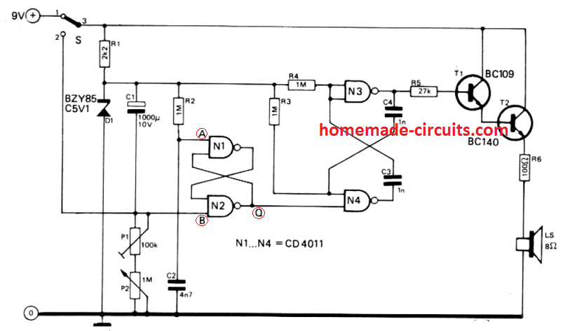
Other time ranges may be possible through little alterations. Initially while the circuit is not powered, capacitor C1 and C2 are uncharged.
As soon as the unit is turned on with switch S (position 1), input A of the flipflop N1 /N2 stays temporarily at '0V', to ensure that output Q of N2 turns into 0 and multivibrator N3/N4 is disabled. Next, capacitor C1 begins charging through potentiometer P1 and P2.
Once the voltage at point B becomes lower than the flipflop's switching threshold, the flipflop toggles and this initiates the multivibrator action.
This initializes the square wave frequency from the multivibrator which is amplified by the transistors T1 and T2 and the resulting tone output is reproduced through loudspeaker L.
When the kitchen timer is switched OFF (S moved to position 2), capacitor C1 begins discharging swiftly via resistor R1 to ensure that, once the timer switched on again for the next cycle, no left over charge remains in the capacitor which may otherwise cause reducing the timing length.
How to Calibrate
1. Adjust P1 at the center of its journey and adjust P2 to its minimum setting range. After that readjust P1 to allow a period of 1 minute.
2. Next, set up P2 to its maximum possible range and determine the time interval generated from the circuit.
3. Lastly calibrate the scale of P2 with a linearly increasing scale from a range of 1 minute minimum, and the maximum which was determined practically earlier.
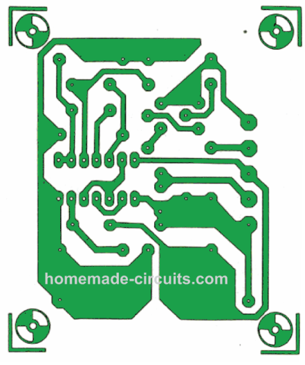
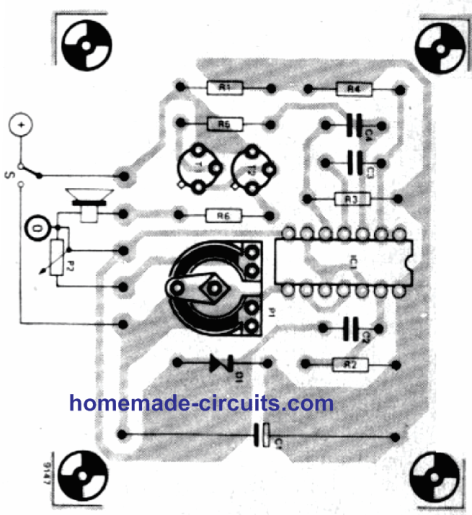
PCB Design and Component overlay