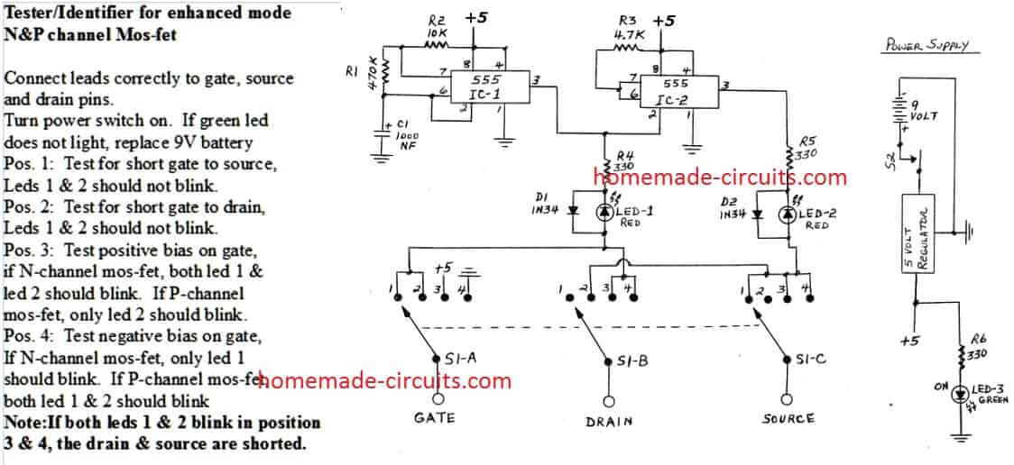
This simple MOSFET tester does a quick job of testing both enhanced mode type N and P-channel mosfets. It checks for shorts between gate, drain and source.
Designed By: Henry Bowman
It also distinguishes between N and P-channel mosfets. Once the connections are correctly made to the mosfet, all testing is done without reversing connections. This saves handling the pins and static buildup, which can produce erroneous results. This project uses a similar principle that I used to design a transistor test/identifier.

Circuit Operation:
IC-1 is a 555 timer IC configured as an astable multivibrator. It produces about two output pules per second.
The frequency is determined by R1, R2 and C1. The output of IC-1 is connected to resistor R4 and the trigger input lead of IC-2. IC-2 is also a 555 timer IC and configured as an inverter.
The output pin 3, of IC-2, is always the opposite polarity of the output pin 3 of IC-1. IC-2's output is connected to resistor R5. R4 and R5 provide current limiting to diodes D1/D2 and Led 1/2. The diodes and leds are connected to a 4 position, 3-gang rotary switch.
The three common leads of the rotary switch are connected to test posts labeled "gate", "drain", and "source" for mosfet connections. PG type clips with cords should be attached to the three binding posts for easy connections to the mosfets.
How to Test
When a mosfet is correctly connected to these connections and the power switch is turned on, the tests are as follows:
Position #1: Tests for a short between the gate and source connection. The outputs of IC-1 and IC-2 are continually reversing polarity.
If a short exists between gate and source, a current path is provided for Led-1 and Led-2 as both 555 ic's alternate polarity. If no short exists, no Led's will light.
Position #2: Tests for a short between the gate and drain connections. Moving the selector switch to position #2 also moves the Led connections to gate and drain. If no short exists, no Led's will light.
Position #3: Provides a positive bias to the gate, while drain and source are connected to the Led's. If the mosfet is N-channel, both Led-1 and Led-2 will blink. If the mosfet is P-channel, only Led-2 will blink. This indicates the normal diode function between gate and source. (See note below)
Position #4: Provides a negative bias to the gate, while drain and source are connected to the Led's. If the mos-fet is N-channel, only Led-1 will blink.
This indicates the normal diode function between gate and source. If the mos-fet is P-channel, both Led-1 and Led-2 will blink. (See note below)
Note: If the mosfet's drain and source are shorted, then both Led-1 and Led-2 will flash in test position #3 and test position #4, regardless of N or P channel. This is how a drain-source short is determined.
Parts List:
Qty - Description
2 ---- 555 Timer IC's or 1 Dual Timer 556
1 ---- 470K 1/4 watt resistor
1 ---- 10K 1/4 watt resistor
1 ---- 4.7K 1/4 watt resistor
1 ---- 1000 NF electrolitic capacitor 20 WVDC
3 ---- 330 ohm resistors 1/2 watt
2 ---- 1N34 general purpose diode, or equivalent
2 ---- Light emitting diode, red
1 ---- Light emitting diode, green
3 ---- Led mounting sockets
1 ---- Selector switch, 4 position, 3-gang
1 ---- Selector switch knob
1 ---- Toggle switch, spst
1 ---- 5 volt regulator 7805, or equivalent
1 ---- 9 volt battery
1 ---- 9 volt battery holding clip
1 ---- 9 volt battery post connector
3 ----binding posts for test connections
1 ----small apparatus box