In this article I have explained a simple digital power meter circuit which can be installed in homes for getting an instant reading of the wattage being consumed by the attached appliances or the loads. The idea was requested by Mr. Nitin.
Technical Specifications
I m going through a problem. I want to know a option that I can fix on my lift so that I get to know the exact total time of my lift when it is used.as I want to calculate the total units consumed by my lift in 24 hrs with 5 kw motor on it. If u can sort it out it will be a great help
Thanx Nitin
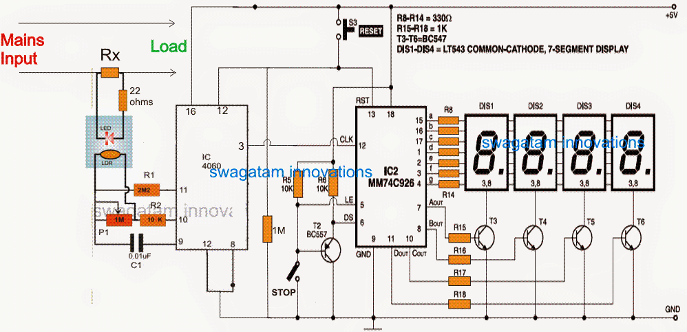
A simple power meter for measuring power usage can be made using a couple of inexpensive ICs and a few associated parts, as shown below:
Circuit Diagram

The Design
Referring to the proposed digital power meter circuit above, we can see the IC 4060 configured as a voltage to frequency converter, while the IC MM74C926 forms a frequency counter stage capable of counting upto 9999 pulses continuously through the connected 4nos of 7 segment common cathode displays.
The IC 4060 is actually a counter divider IC which is configured in a rather unusual way here for achieving the voltage to frequency conversion.
In the normal mode the preset P1 can be adjusted for increasing or decreasing the frequency generated by the IC at its pin#3, however as can be seen in the diagram, an LDR/LED arrangement is connected parallel with the P1 preset, such that the LDR effectively changes the P1 value in response to the illumination intensity of the concealed LED integrated with the LDR.
Determining LED Brightness
The LED brightness is controlled or determined by the current flowing through Rx. The current through Rx is directly proportional to the wattage consumed by the attached load. Therefore if the load consumption increases the current through Rx increases, which in turn increases the pin#3 frequency of the the IC.
Since the pin#3 of IC 4060 is attached with the clock input of the pulse counter circuit, the varying frequency equivalent to the load consumption is counted by this stage and is displayed over the connected 4 display modules.
The STOP switch can be switched ON anytime to freeze the display reading, may be during end of the day when the final reading is to be studied.
For resetting the display and begin the counting afresh, the given reset button can be pushed and released momentarily.
Calculating Limiting Resistor Rx
Rx may be calculated as per the given.
Rx = LED forward voltage drop / Maximum allowable wattage for the load.
For example, if the LED Fwd voltage is 1.5V (for red LED), and the maximum allowable wattage is 2000 watts at 220V AC, then the calculations can be implemented as follows:
2000/220 = 9 amps
Rx = 1.5/9 = 0.16 ohms
resistor wattage = 1.5 x 9 = 13.5 or 15watts approximately
P12 can be used for adjusting or fine tuning the range of the watt meter suitably.
The entire circuit could be powered from a 5V supply, which could be acquired from a cell phone charger unit and after regulating through a 7805 IC.
If the 4060 converter stage looks a little crude to you, you can opt for an alternative voltage to frequency converter circuit, for getting a more professional response from the discussed power meter circuit.