Video Demonstration

An IR proximity sensor is a device which detects the presence of an object or a human when it is within a predetermined range from the sensor, through reflected infrared beams.
Three useful proximity sensor concepts are explained here, the first concept is based on an ordinary opamp LM358, the second one using IC LM567 which functions with a phase locked loop principle ensuring very accurate response for the detection.
The third circuit works using the ubiquitous IC 555.
I have explained each one with a step by step explanation.
Overview
There is a long list of sensors that are available in market today.
One such sensor is proximity sensor.
In this post , we are about to unravel how a proximity sensor works and what provide the necessary knowledge to make this project at home.
As the name suggests, the unit detects whether an object is near or far from it. They can be designed in different ways.
But, the most common method is the one based on INFRARED rays and OPAMP. Some common uses of this device can be seen in cell phones, automatic flush systems, automatic taps, hand dryers and never-falling robots.
Components Required
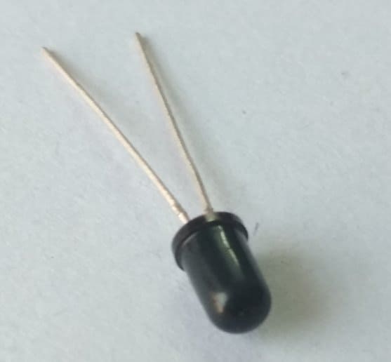
1. IR led: Every led emits some form of electromagnetic radiation when powered up. From our household experience, we have known leds that emit visible light.
But, there are also some special leds that emit infra red rays. Just as there can be visible led of different colours , IR led also emit rays of different wavelengths.
Infrared rays can be of varying wavelengths and can take up any value belonging to their waveband.
So , it is very important that the IR photodiode used must be able to detect the particular wavelength of INFRA RED given out by the IR led.

2. IR PHOTODIODE: It is a special type of diode which is connected in reverse bias for IR rays detection. In the absence of IR radiation , it has a very high resistance and practically zero current passes through it.
But when the IR rays fall on to it ,its resistance decreases and a current proportional to the intensity of the radiation is allowed to pass through it.
This property of photodiode is used to generate an electric signal in proximity sensor on incidence of IR rays.
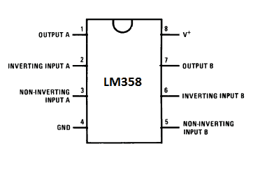
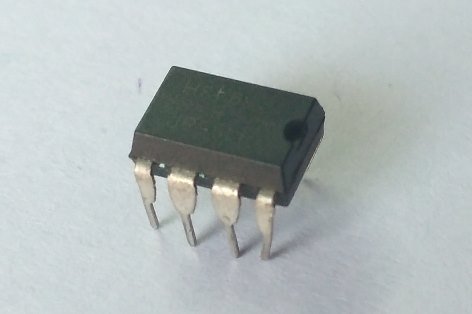
3. Op-amp (IC LM358): Op-amp or operational amplifier is a multi-purpose ic and is highly revered in the electronics world.
In this project op-amp is used as a comparator. LM358 IC has two op-amps which means we can make two proximity detectors using just one IC.
The reason to use op-amp in the circuit is to convert analog signal into digital signal.
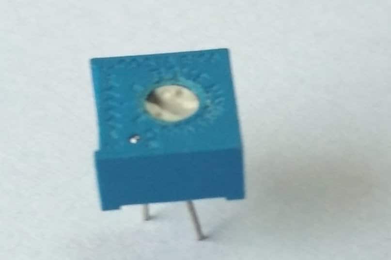
4. Preset: Preset is basically a resistor having three terminals.
The function of a preset is to divide the total voltage available in a way that the user can access a fraction of it. We just have to set the middle terminal to an appropriate position.
The preset sets the threshold voltage above which the output voltage should be generated. It can be manually set to resistance of any value by rotating its head using a suitable screwdriver.
5. Red led : I have used a red led for my project but in general led of any colour can be used. It acts as a visual signal to show that the obstacle has come close enough.

6. Resistors: Two 220 ohms and one 10k ohm.
7. Power supply: 5 v to 6v.
How it work
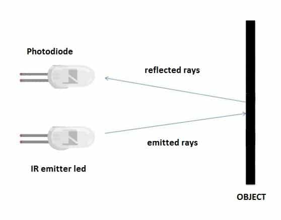
The principle lying behind the working of a proximity sensor is fairly simple. A typical concept has two leds parallel to each other – IR emitting led and a photodiode.
They act as a transmitter-receiver pair. When an obstacle comes in front of emitter rays, they are reflected back and intercepted by the receiver.
As per the properties of the photodiode ,the intercepted IR rays decrease the resistance of the photodiode and the resultant electric signal is generated.
This signal in practice is the voltage across the 10k resistor which is directly fed to non-inverting end of op-amp.
The function of the op-amp is to compare the two inputs given to it.
The signal from the photodiode is given to the non-inverting pin (pin 3) and the threshold voltage from potentiometer is given to the inverting pin (pin 2).
If the voltage at the non-inverting pin is greater than the voltage at the inverting pin the op-amp output is high otherwise the output is low.
All in all, op-amp converts analog signal into digital signal in this circuit.
OUTPUTS:
The sensor output can be used in two forms: ANALOG and DIGITAL.
Digital output is in the form of either high or low. Digital output signal of a proximity sensor can be used to stop the motion of an obstacle-avoiding robot.
As soon as, the obstacle comes close enough, signal can be directly fed to the input pins of motor driver to stop the motors.
Analog output is a continuous range of values from zero to some finite value. Such signal cannot be directly given to motor drivers and other switching devices.
First they need to be processed by the microcontrollers and converted into digital form through ADC and some coding.
This output form requires an additional microcontroller but eliminates the use of op-amp.
Full Circuit Digaram

UPDATE from Admin
The above circuit design could be also built using an ordinary single opamp IC 741, as shown below:

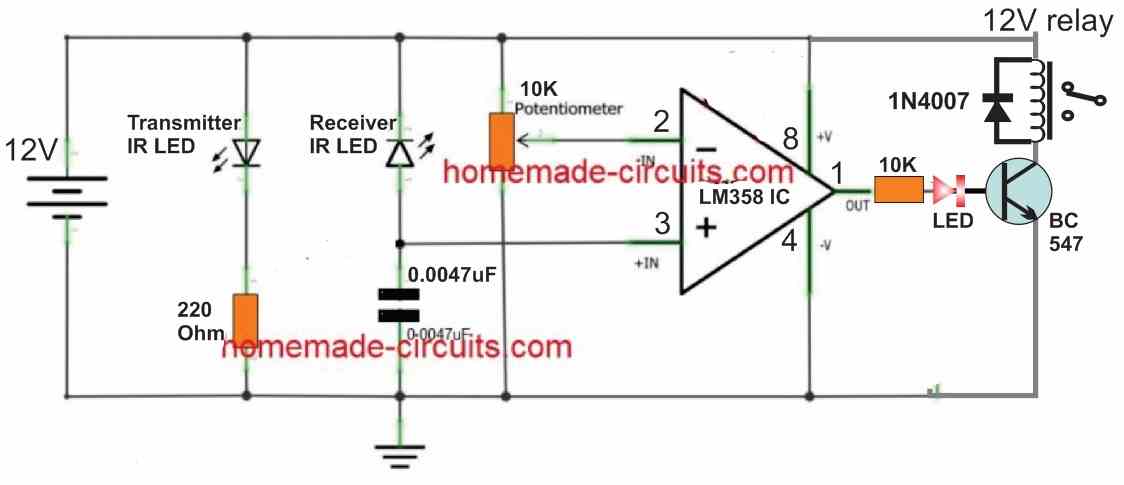
Proximity Sensor with a Relay and IC LM358
The above explained proximity sensors can be also used with a 12V supply and a 12V relay, as shown in the following figure. The op amp used is from the IC LM358.
Using a Relay and IC 741
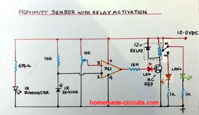
The transmitter and the receiver IR LEDs can be also configured with the IC 741 for making a simple proximity sensor circuit. The entire diagram is given in the following figure:
2) Accurate Proximity Detector Circuit (Immune to Sunlight)
In this post I have explained an accurate infrared (IR) based proximity detector circuit which incorporates the IC LM567 for ensuring reliable, and foolproof operations.
This circuit is immune to sunlight or any other ambient light, and will not get affected, until the tuned reflected signals is received by the sensor.
The design also works as an obstacle detector.
The Circuit Concept
I found this design on the net while searching for an accurate and reliable yet cheap proximity sensor circuit.
The circuit may be understood with the help of the following description:
Referring to the below shown infrared (IR) motion detector circuit, we see the design consisting of two main stages, one involving the IC LM567 while the other with the IC555.
Basically the IC LM567 becomes the heart of the circuit which solely performs the functions of the generating/transmitting the IR frequency and also detecting the same.
Moreover the IC has an internal phase locked loop circuitry which makes it highly reliable with frequency detecting circuit applications.
It means once it reads and latches to a given frequency, its detection feature gets locked to that frequency and therefore any other stray disturbance no matter how strong it may be doesn't influence or rattle its functioning.
Circuit Operation
An internal oscillator frequency determined by R3, C2 feeds the IR diode D274 via a current controlled stage consisting T1, R2. This frequency decides the center frequency of the chip.
With the above conditions the IC gets set and centered at the above frequency generating a constant high at its output pin#8.
Input pin#3 of the IC waits to receive a frequency which may be exactly equal to the above "centered" frequency of the IC.
The IR receiver or the sensor connected across pin#3 of the IC is positioned exactly for this purpose.
As soon the IR beam from the LD274 finds an obstacle, its beam gets reflected and falls on the appropriately positioned detector diode BP104.
The IR frequency from the LD274 now passes to the input pin#3 of the IC, since this frequency will be exactly same to the set center frequency of the IC, the IC recognizes this and instantly switches its output from high to LOW.
The above low trigger at pin#2 of the IC 555 which is configured as a monostable in turn switches its output high, causing the connected alarm to blow.
The above condition persists for so long as the interruption from of the IR sensor/ detector stays and allows the beams to get reflected.
With the inclusion of R9 and C5, the output of IC555 exhibits a certain delay off condition for the connected buzzer even after the motion or the obstacle moves away.
For adjusting the delay-off effect, R9 and C5 may be tweaked as per preference.
The above explained circuit may also be used as a proximity detector circuit and obstacle detector circuit.
Circuit Diagram

Test Circuit
The following test circuit shows how to verify the results from a basic LM567 IR based design. The schematic can be seen below:

As you can see, only the LM567 stage is incorporated in the design while the IC 555 stage has been eliminated in order to keep the fundamental testing procedures simpler.
Here the red LED at pin#8 of the IC lights up and remains illuminated as long as the IR LEDs are held parallel to each other within a distance of 1 foot.
If you try replacing the Tx infrared red transmitter LED with some other external source having a different frequency, the LM567 is stop detecting the signals and the red LED will stop glowing.
The photo diodes are not crucial, you can use any similar or standard photo diodes for the transmitter and receiver LEDs.
Video clip for the above test set up:
3) Another IC 567 based Proximity Sensor Design
Just as above, the exceptional feature regarding this circuit is that it cannot be activated or rattled by direct IR radiation, rather only reflected IR radiation hitting the detector will trigger the circuit.


In the center of the circuit is a solitary 567 tone decoder IC (U1) that executes a twin functionality: it runs both as a basic IR-transmitter driver and as a receiver.
Capacitor C1 and resistor R2 are employed to fix U1's internal oscillator frequency to around 1 kHz.
The square-wave output from U1 at pin 5 is applied on the Q1 base. Transistor Q1 is set up as an emitter-follower amplifier, which connects a 20-mA pulse on the LED2 anode.
Transistor Q3 picks up the IR output from LED2 and directs the transmission on to Q2 for more amplification.
Following amplification by Q2, the signal is applied back to the input of U1 at pin 3, triggering pin 8 to become low, switching ON LED1.
When required, LED1 could be substituted with an optocoupler to toggle virtually any AC-operated load. Because the circuit is very straightforward, almost any design plan will work.
The IR emitter (LED1) and the phototransistor (03) must be installed approximately inch separated within a side-by-side placement and focused in the exact same track.
It may be required to test out the spacing and installation viewpoint of the a pair of IR devices to figure out the perfect position for any assigned range between the detector and the emitter.
As a rule of thumb, an inch gap between the IR-emitter/detector pair makes it possible for the proximity circuit to discover a target approximately half to 1-inch apart.
Lighter shaded targets reflect much better and can perform at increased distances than those created from deeper elements.
So long as the proximity sensor picks up the tuned IR signals, the controlled circuit continues to be turned on, and as soon as the signal vanishes the output turns off.
Proximity Detector using LM567 and OPB711 optocoupler
The electronic diagram of this important part is shown in the figure below.
The use of a small opto-reflective sensor will allow us to utilize infrared radiation emitted by the IC2 circuit's emitting diode (pins A and K).

Unlike traditional integrated or forked opto-couplers, the IR beam from the emitter is directed outward from the package at an angle of a few degrees.
The receiving phototransistor is also oriented at the same angle in order to achieve a convergence point a few centimeters away from the sensitive surface.
If no obstacle "reflects" the emitted beam, the sensor will remain inactive.
An object, or even just a hand, is sufficient to validate the signal and enable its further processing.
To ensure perfectly reliable operation even in bright light conditions, we will control the emitting LED with a periodic signal of a precise and relatively high frequency.
To achieve this, let's examine the IC1 circuit labeled NE567N.
This circuit is commonly used as an ultra-selective frequency decoder. It has its own internal time base, which can be supplemented externally by resistor R5 and capacitor C2.
The central frequency of our sample is simply calculated using the following relationship:
f = 1/R5 * C2 = 1/0.012 * 0.033 = approximately 2.5 kHz.
This rectangular signal is available at pin 5 of the IC1 circuit.
By injecting a signal of the same frequency at pin 3 of the decoder, the internal PLL would perform the comparison, and in case of a match, the circuit's output at pin 8 would be set to a low level.
Using the PNP transistor T1, which is driven on its base through resistor R3 by the same signal, we supply power to the emitting LED of the IC2 sensor.
When there is reflection, the phototransistor collects a signal with reduced amplitude (adjusted by adjustable P1) but with the same frequency.
If the sensitivity is sufficient, the IC1 circuit validates, through R9, the T2 transistor responsible for driving a small relay at the output.
One of the relay's contacts is also used to illuminate the indicator LED L1 through limiting resistor R10.
Capacitors C3 and C4 provide filtering to improve the operation of the entire system, which should be powered by a voltage close to 5V.
In fact, to best suit our relay, the power supply voltage is set at approximately 6V without damaging the IC1 circuit.
It should be noted that the control signal can range from 0.01 Hz to 500 kHz, and the open-collector output at pin 8 is capable of supplying 100 mA to ground.
4) Proximity Detector Using IC 555 Circuit
In this third design we discus a simple IC 555 based proximity detector circuit which can be used for detecting human trespassing from a distance.
Circuit Operation
An infrared proximity detector can be considered as one of the most valuable and widely used circuits in electronic automation application range.
We can typically see it being used in automatic water dispensers, automatic hand dryer units and some specific variants may be witnessed in the automatic doors of department stores.
Working principle of the proposed proximity detector circuit using IC 555
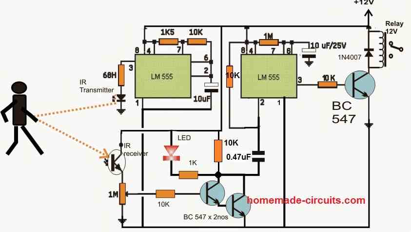
In the design a generation of rapid bursts of peak voltage pulses from the IC LM555 is implemented at a relatively lower frequency rate, which is transmitted via the infrared LED as jets of IR beams.
These transmitted pulses are focused toward the area which is required to be monitored, and is reflected back when a subject or intruder is detected over a phototransistor diode positioned strategically for receiving these reflected signals..
Once this happens the received signals go through processing in order to enable an attached relay mechanism and subsequently an alarm device to get activated.
To test the above implementation an object may be introduced across the zone of the IR beams and the response may be checked by monitoring the relay operation, such as by moving hand in the focused area, within a distance of about 1 meter.
When the reflected signals hit the phototransistor, it develops a potential difference across the 1M pot (adjustable) and triggers the associated Darlington stage, which in turn activate the right hand side 555 stage configured as a monostable circuit.
The relay gets activated in response to this and stays ON depending on the monostable predetermined time delay set by the 1M and the 10uF capacitor.
Circuit Diagram
Parts List fro the proposed IC 555 based IR proximity detector circuit.
2-- IC LM 555
2-- IC sockets 8 pin
1-- relay 12 V 5 pin
1-- Infrared Phototransistor General Purpose
1-- Infrared Diode General Purpose
3-- BC547
2-- capacitors. 10 uF / 50 V
1-- 1N4148 diode
1-- red led 5mm
1-- 68 H
1-- 1K5
2-- 10K
1-- 100K
1-- 470 R H All 1/2 W
1-- 10k 1/4 w resistor to be connected in between 1M preset center lead and the BC547 pair
IC 555 Pinouts

What is the value of the resistor labeled “68H”. I’m assuming it’s a 68K resistor
In the last 555 circuit, the 68H is actually a 68 ohm resistor.
Hi swagatam, in the ckt with the ic 555 what does that 10k resistor in the right ic between the pins 2 and 8 do?
Hi Ary,
the two 10K resistors connected across the 0.47uF capacitor is for discharging the capacitor whenever a monostable action from the right side 555 elapses.
Thank you, for anwering. I have another question, is the red led supposed to turn on when the fototransistor receives the ir beams or is it the other way around, it starts on and when fototransistor receives the ir beams it turns off?
The LED is supposed to switch ON when an IR signal is detected.
you have brought up a very wonderful points, thanks for the post.
Hi Swagatham …your ckts are simple and practical ,even for a begginer at 72 yrs age .Regarding this IR ckt may i have one which works on interference principle ? The ckts given here are based on reflective principle ,i suppose .Thanks and blessings ???? ????
Thank you Nalinkumar, I am glad you found the circuits useful.
For interference based proximity sensor, you can perhaps refer to the following article, which explains a few capacitive type proximity sensor circuits:
https://www.homemade-circuits.com/precision-capacitive-touchproximity/
Hi Swagatam, thank you for the prompt reply to my previous question. I have one more regarding the “IC 555 based IR proximity detector circuit”. It is not clear which number pin the positive side of the 10uF capacitor is connected to. Based on the position I have assumed pin 6 of the LM 555 IC but what is printed is pin 8. Please clarify…Thank you…Jack
Thanks, Jack,
The right side 10uF is connected to pin#6 of the IC 555. Yes, the pin number 6 is looking like number 8, but it is pin#6 as correctly assumed by you, since the right side 555 is configured as a monostable circuit.
The IC 555 based IR proximity detector circuit has a 68H transducer connecting to the IR detector.
Questions:
What is the function of the 68H?
What are the specifications of the 68H? Pulses? Voltage?
Is this really a transducer or a resistor? If resistor, how many ohms?
The 68 is actually a resistor…. It should have been written as 68 Ohms.
Hello, I tried to make the lm358 circuit. I planned to use an NPN transistor to power a buzzer, but unfortunately, when I put the led in the circuit it was constantly on. Followed the schematic correctly, and I used all the same components as you. Only added an l7805 regulator because I am using a 9V battery.
The infrared diode is CQY-5402 INFRACRVENA LED DIODA 5mm 950nm 100mA 1,9
The photo diode is SFH 203FA PHOTODIODA 5mm 900nm 20\’
Can you please help?
Hello Christian, did you adjust the preset of the op amp correctly? Focus the IR waves from the transmitter on the receiver IR diode, and start adjusting the preset and check the response.
You can also try the circuit using IC 741 and see if that helps.
I hope you have used the transmitter and the receiver diodes correctly and have not interchanged them accidentally.
It seems the photodiode was picking up light from the sides. I put a black tube over it and now it works. On the output, i put a 10k ohm resistor and bc547b transistor and connected a buzzer to it, everything is working 🙂
Sounds great!! glad the problem is solved now!
Hi Swagatham
Thank you soooo much for sending me all the circuits clearly and solving all my doubts, these circuits look so amazing
Shall try them out when I get some of these parts I require
Thanks again,
All the best to you & God bless
Kind regards
Val
It’s my pleasure Val, Glad you found my replies useful.
God bless you too,
Hi Swagatham
In the first circuit with the 741 how do I get it to operate a relay instead of the led and what is this Analog output at pin 3 and digital output at pin6 please explain
What is the range of sensitivity of this device
3 feet……6 feet ……..????
How to increase the range
Thanks
Hi Val,
I have updated the circuit with a relay in the above article, under the video. The analogue output shows the position where a gradually rising voltage can be measured caused by the photodiode when it is exposed to a varying IR beam. The digital output is the position where either a positive 5V signal or a 0V signal switching can be measured in response to the varying voltage levels produced by the receiver photodiode.
Yes the range from this type of IR diodes will be very less, in fact 6 feet is quite impressive. If you want larger range then you may have to go for TSOP IR sensor with 38kHz frequency.
Hi Swagatham
Thanks for your & time taken to reply to clear all my doubts, it is very very kind of you, bless you
In this post regarding the IC 741 circuit I see the positive line is connected to pin 8 and the output to the relay is from pin 1, unlike the earlier version which showed pin7 to positive and pin 6 output to relay
Shall try this out and let you know ok
Thank you Val,
The IC in the circuit with the relay is not 741, it is an op amp from the IC LM358, I have mentioned the number LM358 on the opamp symbol, you can see it. Surely you can try it. All the best to you
Hi Swagatam!!!
The question about “Proximity Detector Using IC 555 Circuit”.
1. How can I use a RX photo diode instead of a photo transistor?
2. How can I adjust the sensing distance of the sensors? Specifically, I need the sensors to work at a distance of 1 cm, maximum 2 cm?
Would you be so kind as to show me a possible circuit.
Thanks you for future response.
Respectfully,
Jorge
Hi Jorge,
1) You can directly replace the phototransistor terminals with a photo diode. Cathode will go to the positive supply, and the anode to the 1M preset/pot
2) You can adjust the range by suitably adjusting the 1M perset/pot. If the 1M has problems, you can replace it with a 100K preset or pot.
Hi Swagatam!!!
Thank you for the exact answer. I’m very glad I found your site. You explain the principle of operation of the components very well and in detail, quickly answer all questions, not only smart, but also stupid.
Thank you for giving so much time to ordinary users.
Good luck in all your affairs, health to you and your loved ones.
Respectfully,
Jorge
You are most welcome Jorge, I appreciate your feedback.
And one more question. What is the component marked in diagram as 68H?
Sorry, it is wrongly written as 68H, actually it should be 68 ohms.
Hi Swagatam,
I am trying to build a circuit that will increase its output as a person gets closer to the circuit. The idea is to drive an LM3915 to light LEDs based on how close a person is to the device. As a person approaches more LEDs are lit. I’m not sure which proximity circuit to use: IR, capacitive, ultrasonic or whatever. I will post this question under your LM3915 blog also. Thanks!
Hi Norman, that may not be possible using IR circuits. It may be possible through visible light detection from the target’s body. As the person comes closer the reflected light intensity will increase which can be converted to a visual display. However this maybe possible through an ultrasonic circuit or a Doppler effect circuit, as described in the following article:
https://www.homemade-circuits.com/ultrasonic-wireless-water-level-indicator-using-arduino-solar-powered/
https://www.homemade-circuits.com/motion-detector-circuit-using-doppler-effect/
Hi Swagatam,
I am working on an IR proximity switch to energize a ZDS100 alarm driver. I want the proximity switch to be off when the alarm box is setting on a table. If it is picked up, I want the alarm to be energized. I built the circuit and it works when the box(containing the IR sender and receiver) is away from the table and shuts off about 3 inches from the table, but triggers again when the box gets very close to the table. So in effect it has two trigger distances. The IR portion used to turn the alarm on and off is made up of a LM358. The output is driving a BC327 transistor which grounds a relay that provides power to the ZDS100 and the piezo circuit. The piezo is boosted with a tripod piezo boost inductor. I can send you a schematic if required. Thanks!
Hi Norman,
if the circuit is designed to trigger OFF once the box is taken close to the table then it should not trigger ON again while it is being placed on the table, that shows a malfunctioning of the circuit.
You can take the example any of the above proximity circuits, all these designs cannot repeat the ON/OFF while nearing an object.
I am sorry, checking the schematic can be difficult for me due to lack of time, I can only provide help for my own schematics.
I am glad to know about this website. I have learnt from it.
I have been able to to build the sensor using lm567 ic and it worked like magic. But how can I connect it to relay to drive a load?
Thank you for liking this website, appreciate it very much. You can add the following relay stage with pin#8 of the LM567 to switch the relay ON/OFF, in response to an obstacle.
Thanks do much for the swift response. I am very grateful Sir
You are most welcome!
Good day Sir,
I added this relay network but did not get a response. The whole circuit keeps shutting down once I switch the system on. It trips off. Initially I thought the relay was bad, I tried three relays(12v) but got the same result.
What should I do Sir?
The diode was 1N4007 between the coils of the relay. The Sam thing when I tried the system without the 1N4007 diode.
Please help.
Thanks alot
Evangel, the relay circuit provided by me is correct, because the pin#8 is supposed to become low when the IC detects an obstacle. Connect an LED from the positive line to the circuit to pin#8 OF the IC through a 1K resistor….and check the response of the LED in response to an obstacle. If the LED does not respond then your circuit is simply not working. If the LED works then the relay circuit also has to work.
Good day Sir, I did as you have said, the ic circuit working perfectly well but the relay driver isn’t. I don’t know where I missed it.
I connected as instructed
I fed the ic circuit with 9v source
And the relay driver with 12v source.
Although I noticed that when I used a 5v relay it gave a signof picking up but goes off after the first trial .
Please What do I do?
Thank you Sir
Hi Evangel, I am glad the circuit is working, so it means the pin#8 LED is illuminating, right? Remember the pin#8 will be low only as long as a target is present near the sensors, when the target or the obstacle is removed pin#8 will again turn high. I hope you have used a 10k resistor at the base of the relay transistor. Preferably, you must operate the LM567 with 5V, because 9V is the maximum limit of the IC which can be unsafe for the IC.
Also, connect an LED in series with the base of the relay transistor, which will precisely indicate whether the current passing through the transistor base or not. Since we are using an PNP transistor, the anode of the LED will be towards the base, and cathode towards the pin#8 of the IC.
I would recommend trying the following design, since it is a tested design:
" rel="ugc">
I finally used the circuit you recommended and it worked perfectly. I would have tried it long ago but some vital parts weren’t available.
Thanks so much, you have impacted me greatly.
God bless you for this wonderful service you are providing
It’s my pleasure Evangel,
I am glad to help!
Engineer Swagatam, thanks for the good work. Sir, I don’t know what I am getting wrong. The circuit is working well but the bc557 relay driver isn’t. I supplied the ic circuit with 9v (as directed in the article) and supplied the BC557 relay driver with 12v (as you instructed), still I am not getting the complete working.
I noticed that when I replaced the 12v relay with a 5v relay, it responded but breaks. Please Sir what should I do.
Thankks a lot
Hi Evangel, I have answered to your comment, please refer to your previous comment!
In LM567 circuit used photo diode and IR LED s are looks the same . always confuse this type of sensor how to identify from one to another .
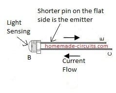
The internal structure of the transmitter LED will be just like an ordinary white LED, whereas the receiver LED will have a slightly different appearance.
There are second hand sensor units avilable on ebay the likes of “2015 Volvo V40 2012 To 2016 Distance Radar Proximity Sensor” are there any circuits available to put these to good use ?
These sensors are designed to work specifically with micrcontrollers, so there doesn’t seem to be an easy discrete solution to process these units
How to design a water sprinkler which starts working while night-time. The LDR (sensor A) detects day light (generates logic LOW signal) and the optical sensor B detects the presence of a person (generates logic HIGH signal). The soil moisture sensor C detect the soil is dry (generates a logic HIGH signal). Design the Water sprinkler (Y) that will turn ON as per the below conditions:
• Night-time and no person is walking
• Night-time and the soil is dry
Hi, What is 68 H in IC555 based proximity sensor?
Is it an inductor?
I cannot find inductor size 68H. I don’t know how does it look like.
Please show example link to such the part.
Thank you
Hi, it is a 68 Ohm resistor, however it looks quite small to me, please use a 1k instead. This circuit was contributed by an external source.
Thank you for reply
0.1 uF is missing from part list. I guess it is non-polarized type capacitor according to schematic.
I wonder what kind of capacitor should be used?
I only know ceramic capacitor for non-polarized type. I guess ceramic capacitor?
Yes it can be a 0.1uF ceramic, however please increase the value to 0.47uF for better response! Also please connect a 10k resistor across the LED for enabling quick discharge of this capacitor.
Sir, how can I adjust the range of sensor made using lm567 tone decode ic?
I’ve already made the sensor but it has fixed range of 12cm. How can I adjust it?
Thanks
Shubham, photo diodes have range in cms only. To get higher range you will have to change the receiver photo diode with TSOP sensor, and adjust the LM567 frequency to 38 kHz
Thanks for the reply.
I get that the photodiodes have less range. But can I adjust it with say a potentiometer in the circuit?
And, the sensor I made outputs LOW when triggered, how can I invert it to HIGH when triggered?
Thanks again!
Shubham, you can reduce the range but cannot increase it.
You can invert the output by adding a BC547 inverter stage
Sir,
I added a transistor to invert the sensor output. I’ve used BD139. But the sensor does not work now.
It only detects when Rx & Tx are perfectly facing each other. Can you help me out?
Thanks!
Shubham, please try the following configuration
Works!
Thanks a lot sir!
You are welcome Shubham!
Hello Swagatam,
you have a project called obstacle avoiding without microcontroller, Can we use this IR concept to avoid obstacles here by attaching motor and wheels? Or you have already such project?
Hi Ritesh, The obstacle avoiding concept already has wheels and motor.
Hello Swagatam sir
I want to make a simple automatic hand senetizing machine using – IR sensor module, motor pump, spray nozzle and timer circuit.
Working of circuit : when ir module sense hand it turns on pump. The pump is connected to a nozzle spray pipe and it spray senetizing liquid on hands for few seconds (1-10) then the spray process will stop automatically and circuit gets reset.
The duration for how long liquid sprays should be adjustable using variable resistor.
Hi Avi,
I have already published a related circuit which you can ee below:
https://www.homemade-circuits.com/automatic-hand-sanitizer-circuit/
But this design is one-shot operation based circuit, because sanitizer pump bottles normally work with a momentary push of the pump handle.
Please specify your sanitizer mechanism, then I’ll try to update the article with a suitable alternative.
Thanks for reply
I actually want to senetize the whole body while a person comes and proximity sensor detects object.
I made my own senetizing liquid and placed in a container connected with multiple spray type nozzle (used by farmer to spray pesticides). The motor pump placed in liquid push the liquid through nozzles for few seconds then it stops automatically. The duration for how long circuit will spray should be adjusted through variable resistor.
OK, you can still use the last circuit which is presented in the previous mentioned link.
You can replace R1 with a potentiometer for adjusting the ON time of the pump. Make sure to add a 10k resistor in series with this pot, otherwise the IC 555 may get damaged while adjusting the pot.
Replace the solenoid with the pump
lm567 based ir detector will work in sunlight ??
because i am using in sunlight it is not working.
i am waiting for your reply
yes it should work because LM567 will respond only to a specified fixed frequency, other stray frequencies will be ignored by the IC.
Here is the basic design enclosure (quick Mock Up)
Slides over the right angle edge piece of the slat. Might have to go surface mount. Ugggghhhhh
?dl=0" rel="nofollow ugc"> ?dl=0
?dl=0
Here is the basic design enclosure (quick Mock Up)
Slides over the right angle edge piece of the slat. Might have to go surface mount. Ugggghhhhh
?dl=0" rel="nofollow ugc"> ?dl=0
?dl=0
Here is what the slat looks like. Not to scale. ?dl=0
?dl=0
?dl=0" rel="nofollow ugc">
Hi Swag! Long Time. Its Bruce L. You assisted me with the Sequential Turn Signal Circuit!
Here is my next use case circuit that I am after. I purchased a new Meat Smoker that has metal slides that slide in between the firebox and the chute where the smoke and heat eminate. There are two slats that need to be slid out after one starts thier charcoal to allow the cooking to begin. Many users forget to pull those slats out and end up wasting thier charcoal as the smoker never comes up to temperature. I though that I would create a device that can slip over the front of the slats (I can 3 D print an enclosure) and has a proximity sensor that is triggered when one walks in front of the slats that are pointed towards the front of the smoker/grill. Then after the proximity has been detected have it blink an array of LED lights as a visual indicator to pull those slats out and not forget.
Since many of the smokers will be placed in an area that has sunlight on them I need a suitable circuit for this enviornment. Let’s say 5(Quantity) 5 mm LED’s for the circuit.
I guess I could mount the sensor slightly recessed in an enclosure which will offer it a sort of hood. Idea’s ? Circuit? Thanks as always for being so helpful!
Thanks Bruce, Yes I remember the chasing light videos that you sent, to demonstrate the success of your car turn light experiment.
For the present requirement, i think you should go for the specialized IR sensor circuit using TSOP which is perfectly immune to all sorts of external signals including sun light, and its range is also good. Here’s the link:
https://www.homemade-circuits.com/how-to-connect-tsop1738-ir-sensor/
For the LED flasher you can probably use a IC 555 astable and connect in place of the relay, and connect the LEDs across pin3 and ground of the astable.
Hi Swagatam!
Thanks so much for the useful article s on proximity sensor 4
circuits.My question is, can these circuits work outdoors ? ( How to avoid false triggers from the sunlight which is a major source of IR)
Thank you adisai, you can use them outdoors, just make sure direct sunlight does not fall on the sensors.
Hello
For distance detective, how could we design the circuit to be sensitive of distance to show the LED turns on in different distance?
Hello, you can replace the receiver sensor with a TSOP IR sensor, that would allow you to proximity distances up to 10 meters or more. However, the transmitting frequency will need to be adjusted to around 38 kHz for ensuring proper working of the circuit
https://www.homemade-circuits.com/tsop1730-33-36-367-38-40-56-infrared/
how to get analog voltage as output from ir sensor circuit. please suggest the circuit
you can read this article:
https://www.homemade-circuits.com/photodiode-phototransistor-working-and-application-circuits/
Dear Swagatham
No, I assembled a different circuit for detector stage. But transmitter, I used your simple 3v IR transmitter circuit. That is a very efficient transmitter.
I made some modifications in a transistorised IR sensor circuit. I used N-Mosfets for motor driving.
I assembled two identical IR based motor driving circuits. I fixed left IR sensor at right side and right IR sensor at left side.
When the right side sensor detect an object, left motor will switch OFF, robot car will turn to LEFT and vice versa.
I got smooth turning for both sides….!!!!!
My practical experience want to share here.
At first I used a 3mm small IR LED, the obstucle detecting distance was only 3cms. Before detecting the object, my car hit the object due to high speed.
Then I just replaced 3mm IR LED with an IR LED from a TV remote control and reduced speed of motor also. The range increased to 15cms, which is morethan enough for an obstucle avoidance small toy car.
Thanks and Regards.
Thanks Anil, you can share it by sending the details to my email ID, I’ll post it here for you!
Hi dear Swagatham
Recently I assembled an IR obstacle avoiding robot. First I tried IR led with series resistor, the distance was very low. Then I assembled a two transistor based IR transmitter circuit from one of your project “Automatic door lock ” I got more than enough range as I expected…….!!!!! But, what I want to do is to replace that circuit with single resistance method for simplicity and save space.
Inthe above posted circuit, supply voltage is 5v, IR Led series resistance 220ohms, IR led current is only 16ma. Will this 16ma emit sufficient IR rays to get minimum atleast 10cm range, when the Photodiode and IR led placed side by side position as in an obstacles avoiding robots toys….?
( I wish to share my idea with you and other readers………
I know, it is very difficult to connect motors properly with wheels for robotic cars. The best solution is to buy a toy JCB with mannual control ( not remote controlled ), remove showel, mechanical arm etc. This JCB has 2 x 6volt geared motors for left and right wheels independently. And also, the back wheel is connected with front wheel, is also a good option.
The same JCB chassis, after modification can be used for LINE FOLLOWING robot too…..
Thanks in advance…
Regards
Thanks for the update Anil,
Did you make the following project?
https://www.homemade-circuits.com/2016/02/obstacles-avoiding-robot-withou.html
yes IR output will depend on the series resistor just like a normal LED, however it has a limit if exceeded could damage the IR LED, you can try the maximum feasible limit for the serie resistor
RC toy car can be easily made using the concept which is I have explained below, it will work reasonably well although the turning movement will not be very smooth.
https://www.homemade-circuits.com/2012/09/make-remote-controlled-toy-car-circuit.html
wish you all the best, and please keep in touch
Wath is the valu for the potentiometer
10k will do.