

This simple refrigerator protector circuit is actually a delay ON timer circuit which makes sure that whenever a power failure occurs or in case abrupt power fluctuations take place, the refrigerator is never allowed to switch ON instantly, rather after a delay of a few moments.
Conventional Protection Features
Today most modern refrigerators are equipped with a protection feature which prevents the fridge from suddenly switching ON or OFF due to sudden power fluctuations or a sudden power restoration.
However, for those fridges which are not equipped with this feature, the following simple delay ON timer circuit can be applied to enable the refrigerator to switch ON after a certain delay, and only when the mains power has become stable.
Until this happens the circuit keeps the fridge switched OFF and monitors until the power has returned to a perfectly normal status.
NOTE: Please use a 50 ohm 1 watt resistor in series with mains input line, otherwise the zener diode may burn during power switch ON.

Circuit Operation
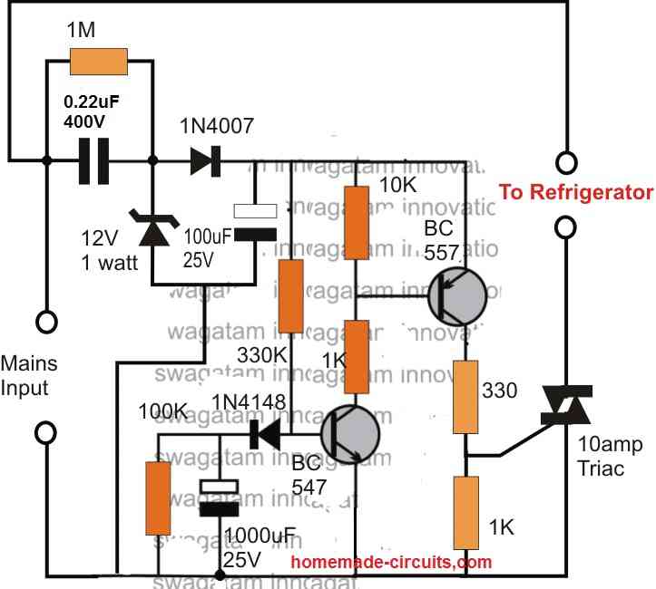
Referring to the above shown refrigerator protection circuit, we are able to witness a two transistor circuit which forms a very basic yet effective delay ON timer circuit, meaning this circuit switches ON its output after some delay, after power is applied to it.
The power supply to the circuit is derived from the mains via a transformerless power supply circuit
which is appropriately stabilized at 12V and fed to the delay circuit.
Whenever power is switched ON, may it be during the first initialization, or during a power failure situation, the associated 1000uF capacitor prevents the BC547 from switching ON at the onset, which in turn keeps the BC557 and the triac switched OFF. The load is therefore unable to receive power and stays switched OFF too.
However, the 1000uF now gradually begins charging via the 330K resistor and when the potential difference across it reaches the approximate total of transistor's biasing limit plus the emitter zener value (0.6 + 3 = 3.6V), the transistor begins switching ON which prompts the BC557 also to switch ON.
The triac now begins acquiring the required gate voltage and within moments switches ON the fridge.
The 1000uF capacitor stays charged as long as power is available to the circuit, and during power failures the capacitor discharges through the parallel 100k resistor so that it can get into the standby mode for the next delay ON cycle operation.
The time delay period can be accomplished by appropriately selecting the values of the 330K resistor, the 1000uF capacitor and the 3V zener diode, as per the user's preference.
This concludes the explanation for the proposed simple refrigerator protection circuit, for any related query please feel free to use the comment box.
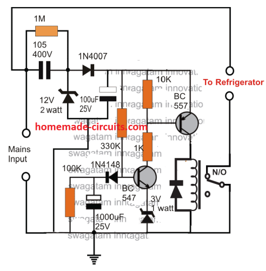
Using Relay
The above design can be used with a relay also as demonstrated below:

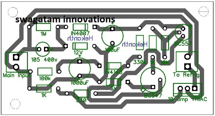
PCB Design (Triac)

WARNING: CIRCUIT IS NOT ISOLATED FROM MAINS... STRICT PRECAUTIONS MUST BE OBSERVED WHILE HANDLING THE DEVICE, WHILE IT'S IN AN UNENCLOSED CONDITION.