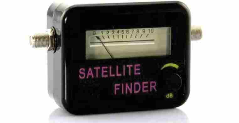
Here I have explained how to make a simple inexpensive satellite signal strength meter which can be used for aligning dish antennas with local satellites in order to achieve the correct positioning and maximum signal strength from the antenna.

How LNB Works
The LNBs that are used for receiving satellite signals (digital or analogue) are designed to grab the entire group of available transponders from the relevant satellite rather than single specific channels.
Due to the high gain features that modern LNBs possess today, the above procedure is likely to induce a whole lot of RF energy into the connected receiver while the dish antenna is optimally aligned.
The proposed signal meter circuit is configured for measuring the magnitude of RF signals over an extensive frequency range by averaging out the overall energy received from all the transponders at once.
It is not recommended to adjust your Meostat dish through this circuit since the power output from this dish could be too low for the meter to detect anything significant and might create confusions.
Image Credit: https://www.shop4fta.com/images/products/satellite-finder-signal-meter.jpg
Circuit Operation
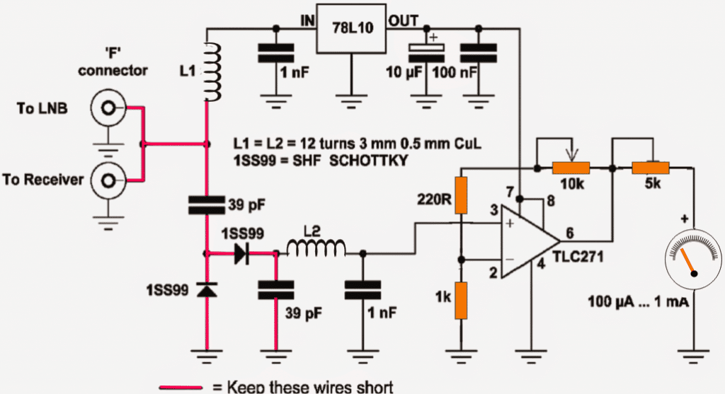
The circuit of the discussed satellite signal strength meter is very straightforward.The IC 78L10 converts the DC extracted from the LNB itself to 10V regulated output for powering the opamp amplifier used for sensing the RF signal strength.
L1 makes sure that the RF from the LNB is not leaked into the supply lines of the circuit in order to reduce signal loss and unnecessary interferences. The 39pF capacitors conversely allows the RF signal from the LNB to pass into the circuit but blocks the DC content from entering the input of the sensor stage.
The silicon fast recovery high speed diode network formed by the two 1SS99 Schottky diodes detect and rectify the acquired RF signals into recognizable DC. It is further filtered by the next 39pF capacitor in line.
L2 and the 1nF capacitors are positioned for filtering any unwanted infiltration that might sneak in along with the actual RF energy to be measured.
Finally the net RF signal is applied to the non-inverting pin of the opamp IC TLC271 which is configured as a high gain, high boost amplifier mode.
The feed back pots included in the opamp circuit are used for aligning and adjusting the gain of the signal meter so that the circuit may be tuned for producing maximum sensitivity and for detecting the minutest possible signal from the LNB.
Subsequently the detected and amplified RF signals is fed to a highly sensitive microammeter unit for translating the signal power into a readable visual output through corresponding needle deflections over the meter.
Circuit Diagram

How to Use the Satellite Signal meter Unit
It may be done by following these guideline steps: Detach the coaxial cable connected across your receiver unit and the LNB (at the LNB end), and simply integrate the signal meter’s input port to the LNB output socket through a small piece of coaxial cable.
After this it’s time to plug in the receiver cable which was disconnected from the LNB to the output port of the signal meter.
The ports provided with this homebuilt signal meter device actually does not have any particular orientation, as it can be witnessed that both the ports are configured in parallel, meaning any of the two ports may be used for the LNB and the receiver, anyway round.
Keep the receiver switched ON so that DC from the receiver is able to reach and power up the signal meter circuit as well as the LNB.
Now direct your dish position approximately toward the satellite zone in the sky, let your favourite tracking program get involved in the set up for determining the compass heading time at occasions when the sun attains identical direction (azimuth) with the satellite.
Optimizing the Control Pots
Next, grab the gain adjustment pot of the signal meter and carefully optimize the setting while you also align the azimuth elevation for getting as significant as possible a deflection on the meter.
Remember, even a variation of as low as a 5 degree from the dish could make the signal vanish instantly forcing you to start the procedure all over again, even worse you may simply tune the dish to receive some vague satellite transmission, therefore do it with great dexterity and with gentle hands.
Once the correct and the most optimal positioning of the dish is achieved, it may be fixed into position by tightening the clamps, After this, the placement of the LNB on the dish rod could also be optimized a bit for enhancing the effects.
