In this post I have explained a simple yet accurate SCR triggered battery charger circuit which can be used effectively for charging all types of battery, which includes, lead acid battery, Ni-Cd battery banks, Li-Ion battery, etc.
This SCR charger can be seen implemented in most automobile garages, and is very popular among auto mechanics, due to the high reliability and low maintenance features of this unit.
Main Features
Since SCRs are used, the full charge cut-off point is sharp and accurate than the transistor based battery charger systems.
Two SCRs are used in this design, one is a high power SCR that charges the battery by supplying the required current, while the other low power SCR monitors the voltage level of the battery, and cuts-off the gate supply to the power SCR as soon as the battery voltage reaches the full charge level.
Since SCRs are available up to even 1000 amps range, the battery charger does not have any range limitation, and almost any battery with highest levels could be used with this charger circuit.
Being completely solid state by nature, the SCR battery charger does not have any wear and tear compared to relay based battery chargers, whose contacts continuously go though sparking and degradation until the relay is ultimately worn out and malfunctioning. But no such issues with this SCR systems, as these devices are very long lasting and can be used infinitely.
Advantages of SCR battery Charger
As discussed above, an SCR based design can have the following advantages over the other conventional types of battery chargers:
- Virtually no wear and tear, therefore highest working life time
- SCRs are available with extreme current ranges, therefore any battery from 1000 mAh to 1000 Ah could be used.
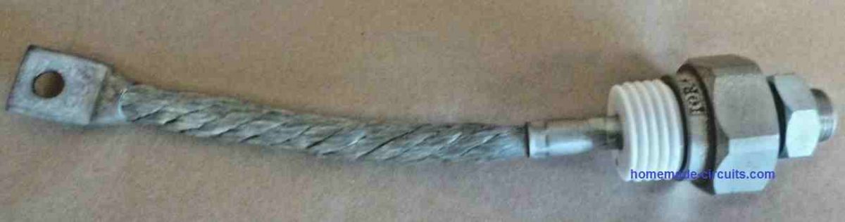
- Large heatsink can be bolted for efficient working due to easy heatsink bolting facility
- Can be triggered with gate voltage as low as 2 V
- Cheaper and compact than MOSFETs, and relays
- Reliable and infinite ON/OFF switching life, due to internal rugged characteristics
- Easy to use and configure
Circuit Description
Referring to the below shown high power SCR battery charger circuit, the main functioning can be understood with the following points:
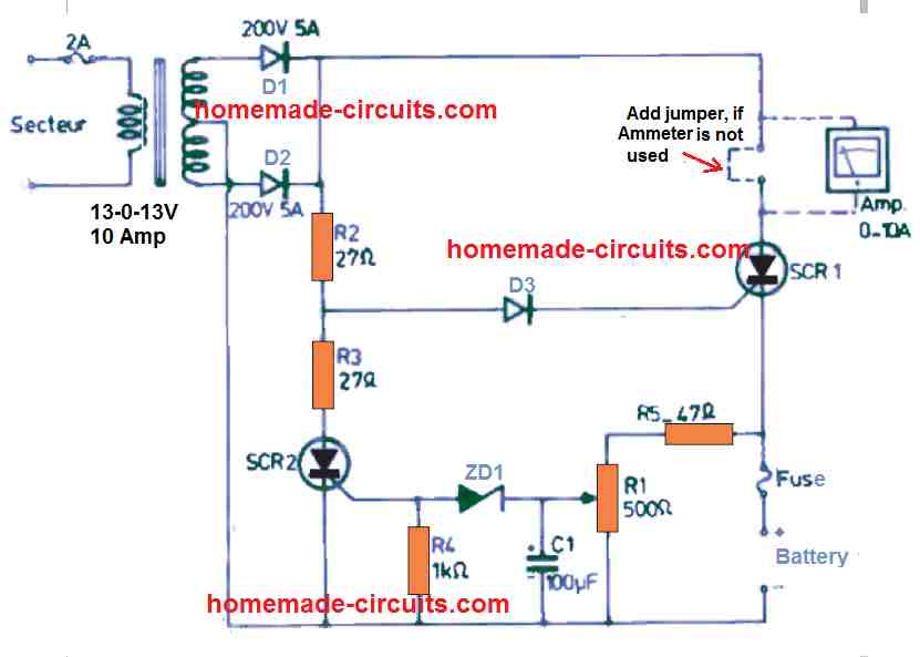
A center tap transformer is used as the power source for charging the battery. It must be suitably rated to handle the battery charging current. Preferably for lead acid battery the current capacity of the transformer must be 10 to 8 times less than the battery Ah value. So for a 100 Ah battery, the transformer must be 12 amps, for 500 Ah battery this can be rated at 60 amps and so on. The stepped down AC from the battery is full wave rectified using diodes D1, D2.
You can see no filter capacitor used after the diodes for two reasons:
- If clean DC is used then the SCR1 will get permanently latched, and cannot be cut-off by removing its gate bias
- Battery usually do not need smooth DC to charge, it is fine as long as the the charge current is a DC, with constant current and full charge cut-off.
When power is switched ON, the capacitor C1 ensures that it grounds the SCR2 gate and inhibits from conducting, regardless of the battery voltage.
With SCR2 switch OFF, the Dc from the D1/D2 easily reaches the SCR1 gate, and triggers it ON.
SCR1 now begins supplying the charging voltage and current to the connected battery across its cathode and ground.
The entire supply voltage from the transformer now drops and settles down to the battery discharge level. This happen because the transformer current is 10 times less than the battery Ah value, which forces it to drop to the battery discharge level. So if the initial discharged level of the battery was 11 V, the DC from the transformer would also drop to 11V and slowly rise as the battery is gradually charged by the SCR1
A resistive divider network built using R1/R5, now begins monitoring the battery voltage. C1 now acts like a filter capacitor for stabilizing the gate input to the SCR2 via the above resistive divider.
Initially the R1 preset is set such that the SCR2 just switches ON when the connected battery reaches its full charge level. For example, for a 12 V battery, R1 can be set such that the ZD1 zener at the gate of SCR2 just begins conducting when the battery voltage has reached around 14.3 V, so that SCR2 is able to fire at around 14,3 V, and cut off SCR1 gate supply.
Therefore, as the battery charges, and reaches the predetermined value, the voltage across C1 is sufficiently high to allow the zener ZD1 to conduct. This in turn, causes the SCR2 to fire, which pulls the gate voltage of SCR1 to ground inhibiting it gate bias.
The SCR2 goes into a permanent latching mode since its gate has a filter capacitor in the form of C1, so it is able to get the required pure DC for the latching purpose.
The above situation causes the SCR1 to shut off, and cut-off the charging current to the battery.
After this, due to absence of a charging voltage the battery voltage starts dropping slowly until it reaches the stable state of charge (SoC), which may be around 12.6 V to 12.8 V for a fully charged 12 V battery.
Since SCR2 is latched, the dropping of the battery voltage to its SoC level does not cause any difference to the shut down situation of the charger.
The SCR charger circuit remains in this condition infinitely until, either the battery is removed or the input power is turned OFF and ON again for a new cycle.
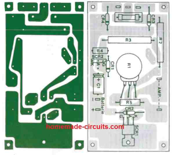
PCB Design
The complete PCB design along with component overlay can be seen in the following image.
How to Set
The SCR charger circuit can be set for the full charge cut-off action, as explained in the following points:
- Connect a partially discharged battery to the circuit.
- Connect an appropriately rated ammeter across the indicate points.
- Connect a voltmeter across the battery, set at the appropriate range.
- Now, switch ON power, so that the battery starts getting charged through SCR1.
- When you find the ammeter reading almost zero, and the voltmeter reading almost reaching the full charge level, start adjusting the R1 preset until the SCR1 is just cut off.
- For indication purpose, a RED LED can be connected in series with R4.
- While adjusting as soon as this LED starts glowing, the SCR2 can be assumed to be switched ON and the SCR1 switched OFF.
- The setting up of the SCR high power battery charger circuit is now complete.
- You can now try implementing the charger with a new discharged battery and witness the auto cut-off process at the set full battery threshold level.
SCR Charger with Trickle Current
The next SCR based battery charger circuit is a trickle charger where the output current drops as the battery voltage increases. Sounds nice, huh? As the battery charges towards the maximum full charge level, the rate of charging is automatically minimized. Go with a 12.6 -volt transformer, effective at providing 3 to 5 amps.
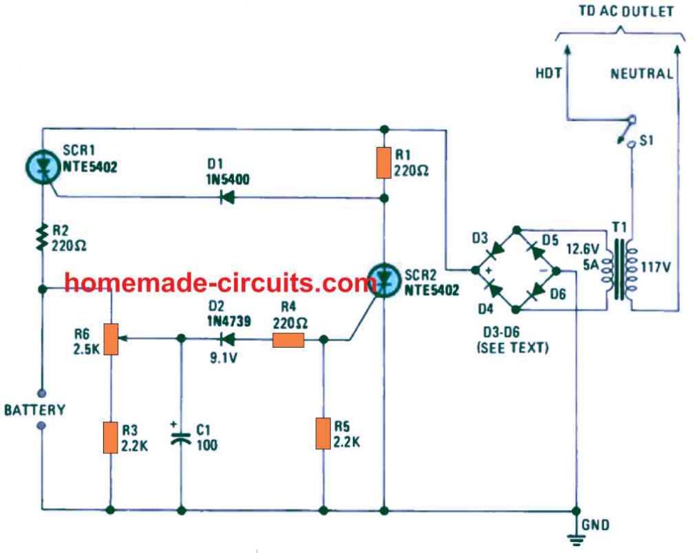
During the time the battery gets the maximum charge current, resistor R1 and diode D1 switches ON SCR1 so that it is able to deliver the the full current to the battery. You can find the voltage over R6 and R3 is fairly low, which causes D2 to stop conducting; turning OFF the SCR2 off.
The voltage from which SCR2 is able to trigger ON is defined by potentiometer R6. When D2 begins transferring gate current to SCR2, it turns on, causing diode D1 to become reverse biased. The voltage for D1, which is pulled by means of R1, declines to practically zero. This prevents SCR1 from activating. The results in a sluggish rate of current and the triggering angle of SCR1 is minimized as the battery terminal voltage goes up.
You can experiment with a limiting resistor, to alter the rate of charging