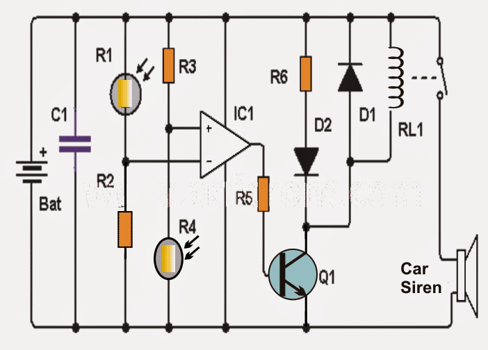
This shadow detector circuit operates using two LDRs and effectively detects the difference between the light levels and triggers a loud audible warning siren.
In circuits which uses a single LDR (photoresist), the detection may not be as sharp as with two LDRs discussed here.Operational details of the shadow detector circuit may be studied as follows:
The key elements of this circuit are the two LDRs and the active operational amplifier, which functions as a comparator.
Circuit Operation
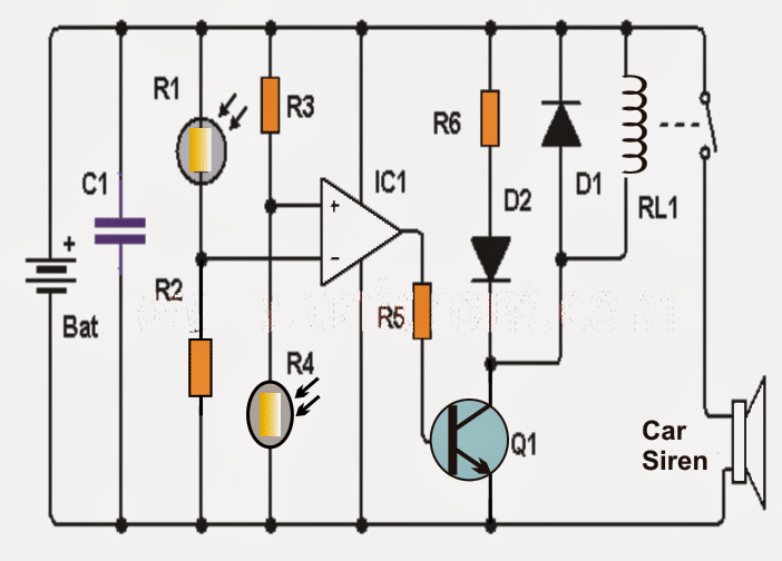
As may be seen in the diagram, the inputs of the opamp are carefully balanced using alternately positioned LDRs across the corresponding supply rails in conjunction with the respective resistors.
The two resistors may be possibly replaced with presets for getting a fine adjustment option and for ensuring an optimum balance and a perfect zero logic at the output of the opamp.
In normal light situations that is with no shadow detected (no shade) the two LDRs are able to receive the same amount of light across the sensing input of the opamp which renders a low logic level at the output of the IC.
In an event when one of the LDRs (for instance R1) experiences a shadow or less light than the other (R4), causes the voltage at the inverting input of opamp to go lower than in the non-inverting counterpart, causing the logic at the output of IC to switch to a high logic.
The above action activates transistor Q1, which in turn activates the LED and the relay. The LED allows to acquire a visual warning while the relay activates a siren device.
Preferably you may want to place a semiconductor diode (D1) in parallel with the relay, as shown in the diagram, to protect the transistor Q1 from the relay reverse EMFs.
Circuit Diagram

Things to be notes:
- The circuit is powered by 9 volt lead acid battery or any similar SMF battery.
- The LDRs should be placed with a separation of about 3cm. for an optimal response and to avoid incorrect triggering.
Parts list for the proposed shadow detector circuit
- 1 Operational amplifier: LM741 (IC1)
- 2 LDRs (photoresistor / LDR) (R1, R2)
- 1 NPN transistor 2N2222 or similar (Q1)
- 1 1N4007 diode (D1)
- 1 red LED diode (D2)
- 9 volt relay (RL1)
- Two 10K resistors (R3 and R4)
- 1 1K resistor (R5)
- 1 resistors 470 (R6)
- 1 100 nF capacitor (C1)
