Tone control circuits are basically filter circuits which are used to filter audio frequency signals so that only the desired range of frequencies are allowed to pass to the amplifier and the loudspeakers.
This enables the listener to customize the music output with either a high level of low frequency content through bass boost, or an increased level of high frequency content through a treble boost.
Tone controls are often an important feature of most audio amplifiers, and these are generally available as bass and treble controls, competent at delivering around 12dB approximately of boost or cut above their specific frequency bands.
While these are extremely straightforward circuits, numerous tone control layouts apparently reveal rather unconventional control features when you do a few mindful inspections with them!
The thing is typically an absence of symmetry in the boost/cut characteristic.
This may not be truly a dangerous drawback, however it does imply that the key control configurations is not going to provide the required flat frequency response.
One reason behind the issue is that several tone control circuits tend to be passive types, and they are as a result determined by having appropriate source and load impedances.
Glitches in either could result in undesirable variations in the responses of the tone controls.
Passive Tone Control
Figure below exhibits the circuit diagram of a basic passive tone control which might work fairly good given that the signal supplied to it is from a low source impedance and passes into a relatively high load impedance.
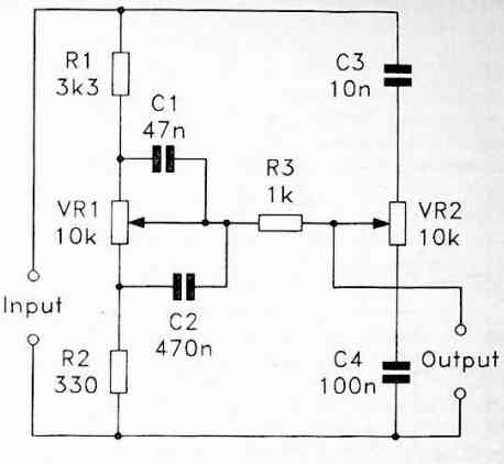
Due to the passive characteristics of the circuit, it isn't actually appropriate to assess in terms of the controls delivering boost and cut.
Such designs will always present losses, and if configured to offer bass or treble boost it is in reality delivering diminished losses instead of a authentic boost to the signal level.
This may not be strictly academic, and the technique in general has to be built to consider the fundamental loss of around 12dB associated with such designs.
Active Tone Control
A passive tone-control network can be connected to the negative feedback loop of a linear amplifier, commonly an operational amplifier, to create an active tone-control circuit. But instead of attenuation, this circuit gives signal gain.
The amplitudes of the output signal are fully regulated through resistor R5 in case the input signals to the circuit shown below are small enough for the capacitors C1 and C2 to function as open circuits.
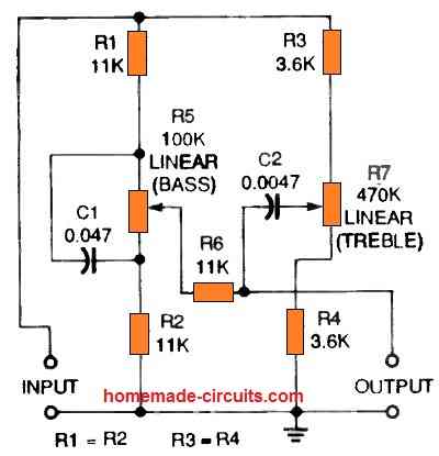
This happens since capacitor C2 isolates resistor R6 from the output.
The amplitudes of the output signal are entirely controlled by resistor R6 at input frequencies large enough to cause the two capacitors to behave as short circuits.
Resistor R5 is short-circuited through C1 in this case.
The values of R1 and C1 decide the low-frequency (bass) circuit cutoff, whereas C2 and the quantities of R1 to R3 define the high-frequency (treble) circuit cutoff.
The next figure below reveals how the design in the above figure can be incorporated into an active tone control circuit which may amplify or reduce bass or treble signals by up to 20 decibels (dB).
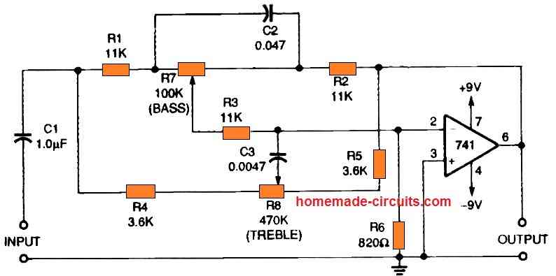
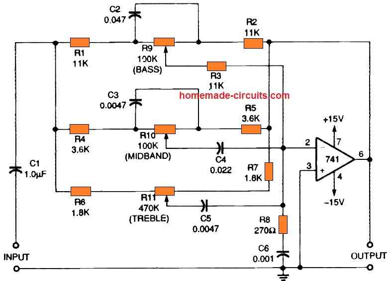
Although comparable to the above this active tone control circuit indicated in the next in figure looks even more flexible.
It contains an extra filter control circuitry that is centered within the audio spectrum's 1 kHz midband. The midband may be enhanced or reduced by up to 20 dB using this network.
It is generally advised that instead of messing with passive circuits, it is better to go for an active tone control circuit like the one demonstrated in the following circuit diagram.
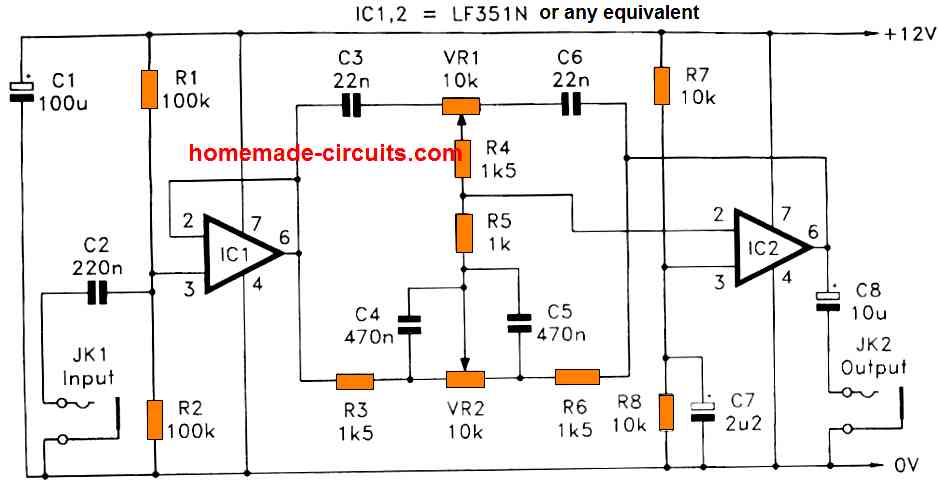
This is simply a passive tone control hooked up from the feedback circuit of a non-inverting op amp amplifier, along with an input buffer stage to ensure that the primary tone control circuit is operated through a appropriately low source impedance.
This offers a kind of inverted results, in which boost from the tone controls supplies increased feedback and decreased gain, while the cut from the controls offers reduced feedback and increased gain.
If the two potentiometers are connected considering these factors, it might be able to deliver the right results through the controls (meaning clockwise movement of the pot will produce boost; and anti-clockwise rotation will deliver cut).
The indicated tone control circuit supplies slightly above 12dB of boost and cut within the opposite limits of the music range.
Simplified Tone Control Design
The next figure below exhibits the circuit diagram of a simplified Active Tone Controls using a single op amp, which is a standard set up possessing bass control VR1 and treble control VR2.
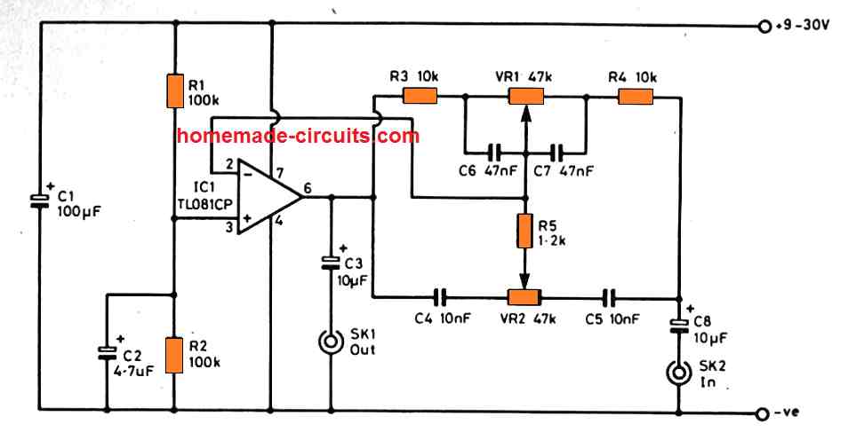
When the wiper arm of VR1 and VR2 are turned fully towards left side, it results in maximum feedback, producing full bass and treble cut.
When the wipers are moved at the opposite side of their rotation we get lowest feedback and thus highest bass and treble boost. The controls don't have any substantial impact at central audio frequencies (around 800Hz), and offer highest boost and attenuation value of approximately 12dB.
The total level of cut and boost is actually offered at the two extremes of the music frequency range, and 12dB is around the maximum that will actually be required in real life use.
1C1 is wired in the inverting mode, and its non-inverting input is as a result easily biased to 50 % of the supply voltage through R1 and R2.
C2 is used for decoupling any noise that might normally be supplied to the non-inverting input through the supply rails through R1 and R2, or picked-up because of to stray coupling.
The amounts of noise and distortion generated by the circuit are minimal, even while the pot controls are adjusted for getting highest possible boost (which still allows the the circuit to have just an extremely minimal level of voltage gain).
As soon as one or both of the tone controls are adjusted for a cut, IC1 offers a closed loop gain of lower than unity.
Using certain inside compensated operational amplifiers a closed loop gain of smaller than unity may trigger instability, and the internal compensation is simply for closed loop voltage gains of unity or higher.
A number of TL081 CP ICs had been experimented with in the circuit and zero complications with instability were encountered.
The circuit may additionally perform nicely using a 741C IC, and in real life use is unlikely that any kind of recognizable drop in efficiency would actually be noticeable employing IC 741.
However, the noise and distortion quantities will probably be somewhat greater compared to the IC TL081CP.
Frequency Response
The next figure below displays the estimated frequency responses from the a couple of control pots, when they are arranged for highest boost and cut.
These responses include pretty excellent symmetry, and the circuit offers a characteristics that's very near to a flat response once the pots are adjusted on the center location.
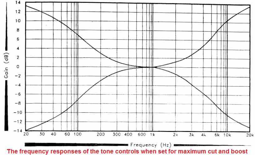
Having said that, remember the potentiometer tolerance can be pretty extensive at around 20%, and that the physical center point of adjustment can be impossible to be the correct electrical center-point.
Any kind of errors caused by this situation within the theoretically flat frequency response could be rather insignificant though. Building of the tone controls provides hardly any issues.
The voltage gain is so minimal, that even if the control is adjusted for getting optimum boost, there could be absolutely no risk of instability.
How to Connect the Pots
Make sure that the pinouts of the pots controls are connected the right way round.
Referring to the two op amp tone control circuit, treble control VR1 delivers boost when its wiper is moved towards the C3 end of the rotation, or oppositely the cut is set when the control is rotated towards the C6 end.
In the same way, bass control VR2 offers boost when the pot wiper is moved towards the R3 end of the rotation, or oppositely the cut is set when it is adjusted towards the R6 end of the rotation.
Observe that you will find a little amount of voltage gain of approximately 5X from the circuit at the 0dB reference level.
3 Channel Tone Control (Bass, Treble, Presence Controls)
The next concept explains a 3 channel tone control circuit, which can be used for generating bass and treble control responses and in addition to this, the circuit can be also used to produce presence control, or the mid frequency control.
The input music signal is applied through connector SK1 to the 1st op amp stage configured around IC1. This is wired as a non-inverting amplifier with a gain that is fixed through the ratio of resistors R3 and R1. For this 3 channel tone control circuit the gain is fixed at unity.
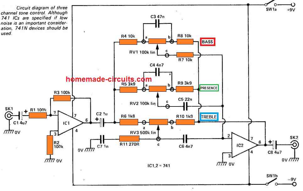
The first op amp stage needs to be kept isolated from the next stage due to prevent loading effects. The ICI output is applied through 3 frequency shaping circuit configurations to IC2.
The three tone controls are constructed around the pots RV1, RV2, RV3 which additionally form the part of the feedback path of IC2, which is configured like another inverting op amp stage.
The parts used around the three potentiometer are selected such that it delivers the intended frequency and tone control results.
Simple Transistor Tone Control Circuit
This simple transistorized tone control circuit can be easily included in any music system such as a stereo amplifier, disco unit or no matter what.
This is because it features a large input impedance (more than 100k), a minimal unity voltage gain and a low output impedance.
The standard bass and treble controls can be seen incorporated in the unit. These filters have around 12 dB of boost and cut at 100 Hz and 10 kHz respectively.
The noise and distortion levels involved in this transistorized tone control circuit tend to be incredibly low because of the massive amount of negative feedback utilized and due to the fact that the circuit is able to deal with output signal levels at many volts rms, without clipping.
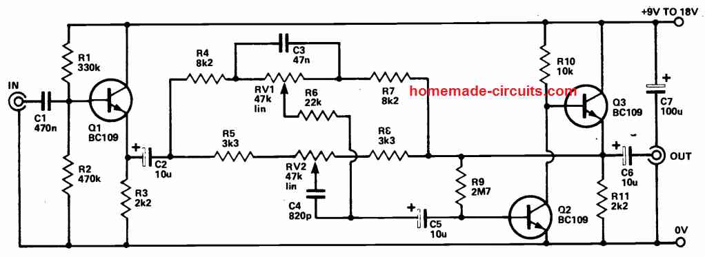
Transistor Q1 is configured in a simple emitter-follower buffer stage which provides the device an increased input impedance. Capacitor C2 connects the Q1 output with the tone control circuitry.
The design is an active tone control circuit that delivers frequency-selective negative feedback to an amplifier.
The amplifier using Q2 is wired as a standard common emitter stage directly connected to Q3 which is an emitter follower output transistor. The latter offers the device a low output impedance.
This tone control circuit is somewhat easier than the typical Baxandall setup, however it is still able to provide a highly realistic performance. Pot RV1 is configured to adjust the bass range of the circuit while pot RV2 controls the treble control.
Feedback is enabled to the highest levels when the potentiometer sliders is shifted to the extreme right, while the feedback becomes the lowest when the pot sliders are rotated fully towards the left.
Needless to say the tone control circuit gain is inversely proportional to the feedback level. Meaning when a maximum feedback is generrated it corresponds to the highest possible cut and not a full boost. The tone control's current consumption not more than 1mA per supply volt.
Treble Booster for Guitars
To increase the higher order harmonics and create a more dazzling sound, a treble booster circuit could be used with an electric guitar (and also musical devices).
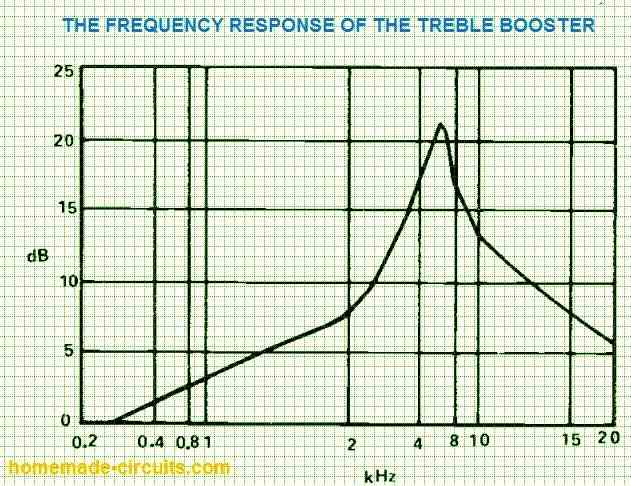
This sort of circuit has a reasonably flat response at bass and over a large section of the middle audio frequencies, with a significant boost at upper-middle and lower treble frequencies.
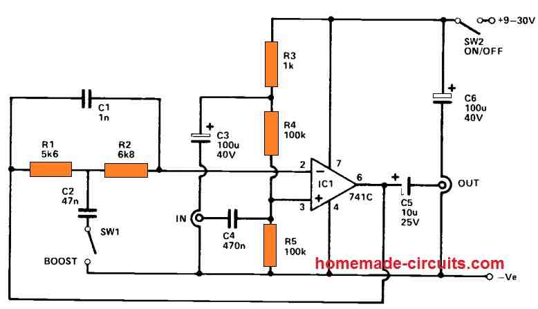
In order to provide high stability and a reduced noise level, it is common to place just a little amount of importance on the upper-treble. This also avoids the output from appearing excessively harsh.
The frequency response is seen in the graph below.
The design is essentially an op amp operating in non-inverting mode.
R4 and R5 bias the non-inverting input through a decoupling network consisting of R3 and C3. DC blocking is provided by C4 and C5 at the input and output, accordingly.
With SW1 in open condition, R1, R2, and C1 provide nearly 100 percent negative feedback, providing the circuit unit gain and a flat response. By closing SW1, part of the feedback via R1 and R2 is decoupled at frequencies greater than just few 100 Hz, resulting in the desired ascending response. At peak treble frequencies, feedback through C1 enables the response to fade away over around 5.5 kHz, preventing the extremely high frequency harmonics from getting over emphasized.
1800 Hz Crossover Network
The circuit below is taken from National Semiconductor Corporation's Application Note AN-346, which introduces the LM833 audio op-amp.
You can very well use another low-noise opamp in this circuit; if they're pretty easy to come by, grab a pair of TL072s or TL082s.
It's worth noting that a split power supply is necessary; it's listed as +15V and -15V, although split +/-12V or even +/- 9V sources would also suffice.
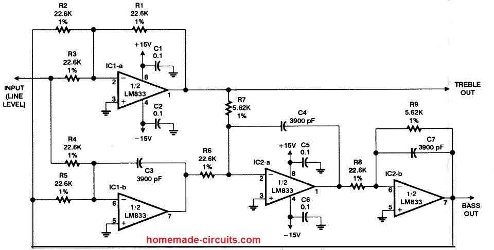
A pair of 9-volt batteries can be used for supplying power to the assembled circuit while testing the prototype. This is a "constant-voltage" crossover, according to National Semiconductor, which indicates that the total of the bass and treble output voltages will be equal at all frequencies. A simple formula determines the crossover frequency:
F = 1/2πRC
In this formula, R represents the resistance of R1, R2, R3, R4, R5, R6, and R8, while C represents the capacitance of C3, C4, and C7. The value of R is represented by resistors R7 and R9.
C1, C2, C5, and C6 bypass capacitors have no effect on frequency response. For the optimum performance, utilize precision parts such as 1% resistors and 1% or 3% capacitors.
The required capacitance, 3900 pF, is alternatively known as 3.9 nF or 0.0039 uF.
FET Tone Control Circuit
An FET based high input impedance tone control circuit with active bass and treble controls is shown in the following image:
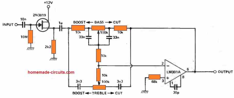
High Quality Stereo Tone Control Circuit using LM833 Op amp
A remarkable stereo tone control circuit can be constructed using just a single LM833. This dual operational amplifier boasts low levels of noise and distortion, making it exceptionally well-suited for applications of this nature.
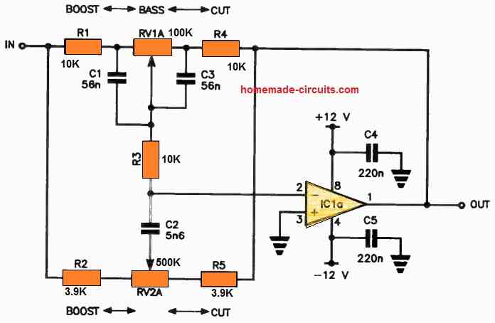
In this circuit, we employ conventional bass and treble boost/cut filters, with only one half of the stereo circuit depicted here. The controls, namely RV1 and RV2, are of the dual-ganged variety.
For the bass boost/cut, the rollover point at -3 dB occurs around 300 Hz, offering a maximum boost or cut of approximately 17 dB at 30 Hz.
Similarly, the treble boost/cut has a -3 dB rollover point at approximately 1 kHz, with a maximum boost or cut of about 17 dB at 10 kHz.