In the previous post I explained a piezo transducer element and learned how to use it with electronic circuits. In this article we will see how a piezo tranducer can be driven or operated using a simple circuit.
As discussed earlier a piezo transducer basically requires a frequency to vibrate and reproduce the required sound.
This property makes these devices typically suitable for buzzer related applications and in warning alarm devices.
So does this mean that if we apply a frequency across the terminals of a piezo transducer, it will start generating the intended sound outputs?
Partially this may be correct but might not be as easy as that.
Basic Working
A thin circular slice of ceramic piezoelectric material placed on a metal diaphragm serves as the fundamental constituent for all forms piezo transducers.
The manufacturer's selection determines the type of ceramic that is utilized. Titanate zirconate and barium titanate are two common substances.
The metal diaphragm is most often composed of brass or stainless steel and has a thickness of less than 0.5mm. Its thin shape guarantees that the metal diaphragm could be quickly activated into a condition of resonant mechanical vibration.
When an AC voltage is passed over the piezoelectric material's electrodes, the body expands and contracts in time with the voltage.
Consequently, sound waves are produced as a result of the metal diaphragm bending in harmony with the ceramic substance.
For best efficiency, keep in mind that the mechanical resonant frequency of the element must coincide with the driving voltage frequency.
Structural Characteristics
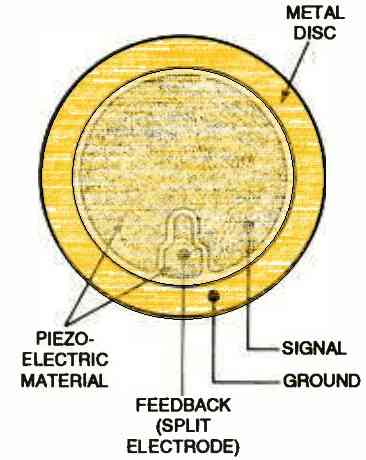
Two main forms of piezoelectric elements are available: two terminal and three terminal. The physical distinctions between the two forms of elements are depicted in the figure below.

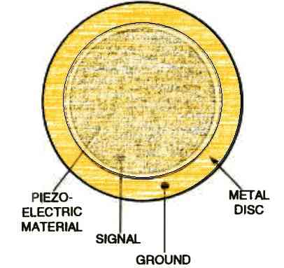
In a two terminal type of piezo transducer, the metal diaphragm works like one electrode, while the piezo element serves as the second electrode. An AC signal is applies across these two electrodes to operate a piezo transducer.
The piezoelectric element in the three-terminal type has a split electrode. When an AC signal is supplied to the primary electrodes, a phase-shifted signal is produced between the split electrode and the metal electrode.
The oscillator/driver circuit is provided feedback from the phase-shifted signal in order to make it resonate at the element's intrinsic frequency.
Piezo Driver using a Single Transistor
A basic "self-drive" piezo driver circuit is shown in the following figure.
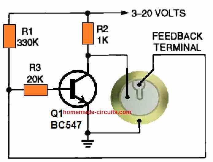
In this oscillator, the inductor and capacitor that typically make up a Hartley circuit have been replaced by a piezoelectric device.
The image provides common component values. The working voltage and resonant frequency can vary from 3 to 20 volts and 2 to 6 kHz, respectively, depending on the specific element and transistor utilized.
How to Operate a Piezo with Maximum Sound
The applied frequency will be required to be amplified very sharply or strongly before it can actually produce the intended effects in the piezo.
However the amplification procedure is not by using conventional amplifying circuits as used in systems incorporating speakers, but rather it is simply implemented through an inexpensive inductor.
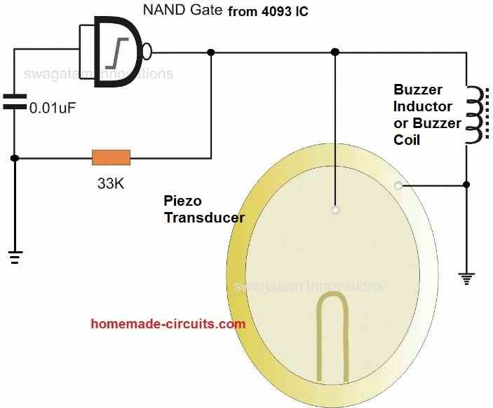
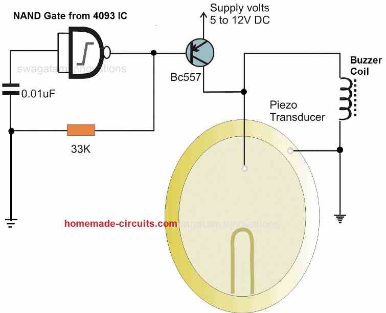
The low power frequency which may be available from a relevant circuit or an IC is first amplified using a transistor, and further more the transistor output is pumped up using an inductor. The use of a inductor becomes the most crucial stage for driving a piezo electric transducer.
The used inductor might not be critical with its value, but the value should as high as possible, the higher the sharper the reproduction from the piezo.
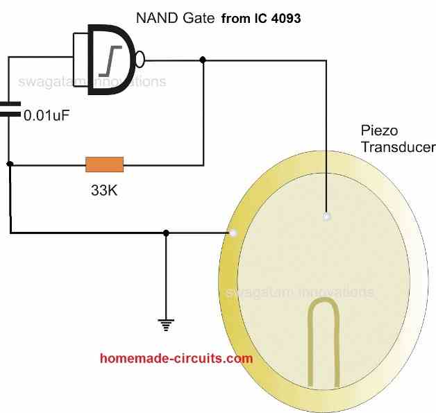
A simple piezo transducer driver circuit or a simple piezo alarm circuit is shown in the following circuit using a NAND gate.
Powerful Piezo Alarm Circuit
In the following piezo alarm driver circuit, a sole quad two-input NAND Schmitt trigger package, denoted as [74LS132], serves as the driving force for a piezo transducer, resulting in an exceptionally powerful output characterized by a piercing, undulating tone.
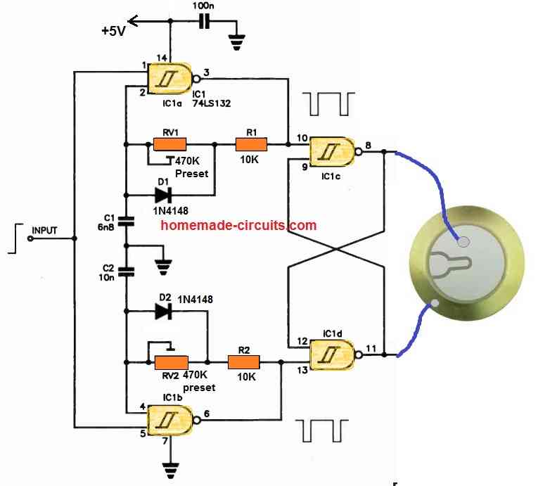
Two integrated circuits, IC1a and IC1d, are interconnected as gated oscillators, offering a mark-to-space ratio of approximately 4:1 through the utilization of diodes. RV1 and RV2 are responsible for enabling frequency adjustments.
These oscillators are meticulously tuned to distinct frequencies, thus generating complete interference between their respective notes, thereby yielding a highly urgent auditory experience when finely tuned.
The outputs from these oscillators are then directed into a flip-flop circuit, comprising IC1c and IC1d.
The push-pull outputs of this flip-flop, in turn, actuate the piezo transducer, or buzzer, delivering the desired sonic output.
The oscillators can be controlled by a high signal level to activate them, while a low signal level deactivates them.
Alternatively, a high-speed CMOS device like HCT can be employed as an alternative to achieve the same functionality.
Piezo Driver with Intermittent Beep Sounds
This piezo intermittent beep sound generator, driver circuit can be utilized as a building block in a wide range of projects.
The best example can be its application as a tone-burst oscillator to operate a piezo transducer directly, and using a transistor to sound an alarm.
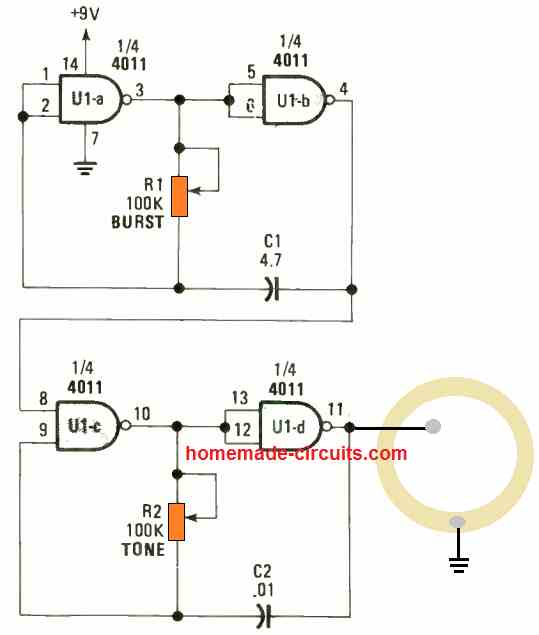
It may be also possible to use the above circuit modulate an FM transmitter so that it creates an intermittent beeping sound on reception. The circuit is made up of a single quad NAND gate, a couple of resistors, and a pair of capacitors.
The first 2 gates are configured as the "burst" oscillator while the third and fourth gates function like a "tone" oscillator. The burst oscillator is a lot slower compared to tone oscillator and is accustomed to pulse the tone oscillator with an intermittent on and off.
Using IC 555
A very simple yet effective piezo driver circuit could be build using a single IC 555 as shown below:
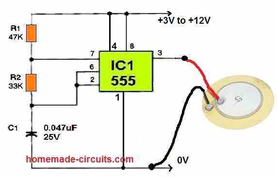
You can try adjusting the values of C1 and R1 for experimenting with the tone output of the piezo driver.
To get maximum sound output make sure to mount the piezo transducer inside a plastic enclosure with an elevated step and a 5 mm hole at the center.
Or you can simply buy a ready-made unit with the piezo fitted inside a plastic enclosure, as shown below:
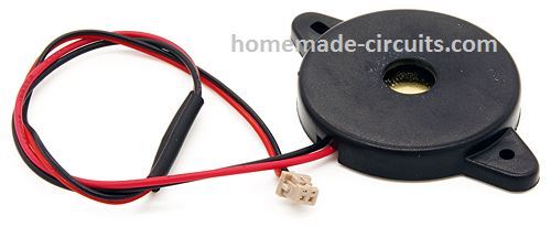
With the above assembly you may find the sound output to be quite impressive. However, if you want the sound to be extremely high and ear piercing, you may consider using a buzzer coil as indicated below:
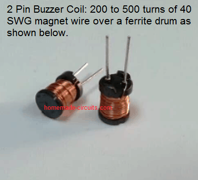
These can be easily procured ready-made from any electronic spare part retailer.
To connect this, simply attach the coil leads across the piezo buzzer wires, or parallel to the piezo buzzer wires. Once done, you may find the piezo driver sound output increasing drastically to an extremely high level.
I’ve got an electronic drum kit and the kicker pedal produces a a continuous steam of beats when the kicker is pressed down only once. I replaced the Pztio sensor but the problem still persists. There are 2 resistors in the pedel I guess a simple potential decider; any ideas what to check next
Hi, without seeing the schematic, it can be difficult to understand the fault and troubleshoot it, so the complete circuit diagram of the piezo stage will be required to diagnose the fault…
Thanks to the tireless electronics and circuit and programming professors
Sir Swagatam, Congratulate on managing this very interesting site full of excellent circuits. could you please explain if all following nouns are the same and denoting on one element? I am a little confused please apologize and help me
piezo buzzer transducer
Piezo electric speaker
piezo electric
piezo buzzer
Piezo electric buzzer
Thank in advance for your reply
Thank you Max,
All the names you have mentioned, they all refer to a single device: a Piezo transducer, which are built using piezo as the core material.
Let me know if you have any further doubts.
Thank you Sir Swagatm for so soon response and for permitting me to ask further questions. I have bought one which produces sound when connecting to battery and is different from those that is seen in your article. There are also bulky ones in the stores.
Thank you very much in advance for your reply.
Hi Max,
The piezo transducer basically should be without an oscillator, meaning it should make the buzzing sound when connected to DC.
Here’s an example of a piezo without an oscillator:
" rel="ugc">
However, since you have bought a piezo buzzer, you can try that in your 555 circuit and check the response.
There are a couple of other transistor circuits that can be used to drive piezo transducers for intermittent beeping. I sent you an email of the schematics.
Thank you so much for sending this intermittent buzzer circuit diagram: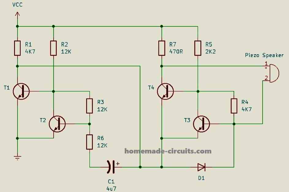
" rel="ugc">
However I could not simulate it in my mind regarding how the oscillator works to generate the beeping sound?
When you have time please check the circuit, whether it works or not,.
Many thanks again.
I have tried both circuits. I don’t know how but they defiantly work.
OK, great, so it is confirmed the above linked intermittent buzzer circuit works, thanks very much for your valuable feedback and contribution. I will update the diagram in a new post and will try to figure out the explanation.
The circuit diagram has an error. You have grounded the coil
No, it is correct. The coil goes between the collector of BC557 and ground, and the piezo is connected parallel to the coil.
looking for a device where a sound activates by wifi or a 110 vac input, to alarm me about 100 ft away by a 120 vac cable into the house, to a volume adjustable, by a pot, , driving a son-alert or ding dong bell, continuously, until input power is shut off
Your help is much appreciated
Hans
Sorry, I don’t have this circuit at the moment which can be triggered using a WiFi.
Hello,
Please could you tell me where i could buy piezoelectric sensor to test outputvoltage when this sensor would be pressed by feet or bikecycle?
Thanks. Gilles.
Hi, you can search the following phrase in Google, you may find many good sources
Try searching “Buy Piezo Transducer”
Hallo,
from an old CO sensor board I removed a piezo-speaker. Now I would like to know if it is an active one or needs a driver circuit like these mentioned above.
It has 3 pins labeld F H and G.
F and H are in the center, G is at the edge.
Thanks
Kinds Regards
Hello, How does the piezo device look like ? If it is same as the one shown in the above diagrams then it will need a driver to operate it.
Thanks for your effort,
the link you supplied did not show any piezo, but I found the partnumber. It is PT-3534FP. It is passive, it needs an external driver.
Thanks again, this is a very good service.
Kind regards
OK great! Got it! It seems it does require an external driver. Further details can be found in the following pdf link:
https://datasheet.octopart.com/PT-3534FPQ-Mallory-Sonalert-datasheet-49213673.pdf
What I struggle to understand is the excitation voltage for the ring. From the square wave file it seems to be 0.5 V with a -4.5 V offset. But the secondary voltage from the documentation is 111.4 V? Which end of the transformer is connected to the piezo?
The objective is under defined excitation voltage (0.5 V at 63.5 kHz with -4.5 V offset) simulate behavior of a PZT-82 piezo ring with defined dimensions attached to a 62% copper tank.
The input signal is a rectangular waveform
I will have to see the schematic to understand your question.
Hello dear Mr.Swagatam
First of all, I appreciate your Excellent website.
I want to drive a mist maker piezo bt86 with an operating frequency of 1.7 MHz, 30 watt and the max of operating voltage is 70v . please guide me. Thankyou
Thank you Ehsaan,
You can try the 3rd circuit from the above article, replace the transistor with a mosfet. You can use an N channel mosfet and connect the piezo at it drain side. The coil or the inductor can be removed if required. The IC must be supplied with 12V, while the piezo can be supplied with 70V
Hello again
I built the oscillator with ic 4011 and set the frequency to 1.7 MHz. But the output does not have the power to run MOSFET. Wich circuit is suitable to amplify the frequency ?Can I use the gate driver for amplification?
Hi, that is not possible, if the frequency voltage is 12V then the mosfet will definitely conduct in response to the frequency. Did you measure the 4011 output with a meter?
the inductor symbol used in the piezo transducer driver suggests a ferrite core choke. Can a simple wire wound inductor be used instead?
No, the inductor has to be a ferrite wound inductor, air core will not work.
how to store pzt genrated electric power
Very nice post, would you kindly explain how one can use a piezo transducer to measure liquid level from the bottom of container like how ultrasonic fuel level sensors work?
Thanks, Glad you liked it. for ultrasonic application, one piezo can be used for transmitting high frequency towards the target (liquid level), another piezo adjacent could be used for capturing the reflected vibrations, and then processing the distance.
Hi Swagatam,
I am looking to build a simple circuit which can light up a 12v LED strip using piezo. Basically trying to use a piezo attached to a drum and light up the LED attached to it. Please help me out.
Hi Rajtilak, It can be difficult to light up a 12V LED strip, since a typical piezo (27 mm) will not generate more than 3V at its optimal capacity.
even a boost charger circuit will not be able to help since the current involved with a piezo output could be relatively low
Hi,
I am not looking to power up the strip with the current generated from the piezo sorry if i had confused you. All i need is using this piezo as a trigger source and get supply from a 12V source. Im still not clear about what i am trying to tell you. I will have a separate 12V DC source, all i need is, when i hit this trigger(piezo) i want the signal to make this strip power up from that 12V source. Please help.
Hi, Swagatam hoping you are well.
Can a 555 timer be used to drive a driverless piezo and please provide a value for the inductors.
I would like to use it in the moisture detector.
I do have a small toy 8 ohm speaker would that be better, but I think it would require a sound generating circuit.
Unfortunately due the virus i cannot purchase directly, only online but the shipping costs are astronomical.
Eg. For 10 cents I’d be paying 100 cents shipping. Thanks so much and be safe.
Hi Moboy, yes it is possible to drive a piezo element directly through a IC 555 astable, by connecting the piezo wires across pin3 and ground, but you will also require a small 100uF inductor parallel with the piezo wires for proper amplification, an the frequency will also need to be adjusted to suit maximum volume.
Thank you Swatagam, I truly appreciate your prompt reply and advise.
I wish you all the best.
No problem, moboy!
Hello,
I need a circuit to produce ultrasonic vibrations. The vibrating element (piezo) has to attach the wall of a let's say glass and the vibrations should detach the bubbles attached to the glass wall at a frequency of about 80 kHz. Do you think this configuration will be helpful?
Hello, yes the last design can be used for the purpose but the piezo will need to be attached correctly so that the vibration do not get dampened
What value should be the coil for a 35Khz oscillator?
you will have to determine the frequency by trial and error method by varying the 33K resistor or the capacitor values and confirming the results with a freq meter
Can third high volume circuit be driven by microcontroller pin generating clock?
yes you can, feed the clock directly to the base of the transistor via a 1k resistor