A very simple yet highly sophisticated modified sine wave inverter circuit is presented in the following post. The use of the PWM IC TL494 not only makes the design extremely economical with its parts count but also highly efficient and accurate.
Using TL494 for the Design
The IC TL494 is a specialized PWM IC and is designed ideally to suit all types of circuits which require precise PWM based outputs.
The chip has all the required features in-built for generating accurate PWMs which become customizable as per the users application specs.

Here I have explained a versatile PWM based modified sine wave inverter circuit which incorporates the IC TL494 for the required advanced PWM processing.
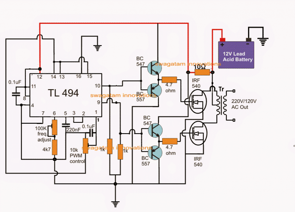
Referring to the figure above, the various pinout functions of the IC for implementing the PWM inverter operations may be understood with the following points:
Pinout Function of the IC TL494
Pin#10 and pin#9 are the two outputs of the IC which are arranged to work in tandem or in a totem pole configuration, meaning both the pinouts will never become positive together rather will oscillate alternately from positive to zero voltage, that is when pin#10 is positive, pin#9 will read zero volts and vice versa.
The IC is enabled to produce the above totem pole output by linking pin#13 with pin#14 which is the reference voltage output pin of the IC set at +5V.
Thus as long as pin#13 is rigged with this +5V reference it allows the IC to produce alternately switching outputs, however if pin#13 is grounded the outputs of the IC is forced to switch in a parallel mode (single ended mode), meaning both the outputs pin10/9 will begin switching together and not alternately.
Pin12 of the IC is the supply pin of the IC which can be seen connected to the battery via a dropping 10 ohm resistors which filters out any possible spike or a switch ON surge for the IC.
Pin#7 is the main ground of the IC while pin#4 and pin#16 are grounded for some specified purposes.
Pin#4 is the DTC or the dead time control pinout of the IC which determines the dead time or the gap between the switch ON periods of the two outputs of the IC.
By default it must be connected to ground so that the IC generates a minimum period for the "dead time", however for achieving higher dead time periods, this pinout can be supplied with an external varying voltage from 0 to 3.3V which allows a linearly controllable dead time from 0 to 100%.
Pin#5 and pin#6 are the frequency pinouts of the IC which must be connected with an external Rt, Ct (resistor, capacitor) network for setting up the required frequency across the output pinouts of the IC.
Either of the two can be altered for adjusting the required frequency, in the proposed PWM modified inverter circuit we employ a variable resistor for enabling the same. It may be adjusted for achieving a 50Hz or 60Hz frequency on pins9/10 of the IC as per the requirements, by the user.
The IC TL 494 features a twin opamp network internally set as error amplifiers, which are positioned to correct and dimension the output switching duty cycles or the PWMs as per the application specs, such that the output produces accurate PWMs and ensures a perfect RMS customization for the output stage.
Error Amplifier Function
The inputs of the error amplifiers are configured across pin15 and pin16 for one of the error amps and pin1 and pin2 for the second error amplifier.
Normally only one error amplifier is used for the featured automatic PWM setting, and the other error amp is kept dormant.
As can be seen in the diagram, the error amp with the inputs at pin15 and pin16 is rendered inactive by grounding the non-inverting pin16 and by connecting the inverting pin15 to +5V with pin14.
So internally the error amp associated with the above pins remain inactive.
However, the error amp having the pin1 and pin2 as the inputs are effectively used here for the PWM correction implementation.
The figure shows that pin1 which is the non-inverting input of the error amp is connected to the 5V reference pin#14, via an adjustable potential divider using a pot.
The inverting input is connected with pin3 (feedback pin) of the IC which is actually the output of the error amps, and enables a feedback loop to form for pin1 of the IC.
The above pin1/2/3 configuration allows the output PWMs to be set accurately by adjusting the pin#1 pot.
This concludes the main pinout implementation n guide for the discussed modified sine wave inverter using the IC TL494.
Output Power Stage of the Inverter
Now for the output power stage we can visualize a couple of mosfets being used, driven by a buffer BJT push pull stage.
The BJT stage ensures ideal switching platform for the mosfets by providing the mosfets with minimum stray inductance issues and quick discharge of the internal capacitance of the fets. The series gate resistors prevent any transients trying to make its way into the fet thus ensuring the operations to be entirely safe and efficient.
The mosfet drains are connected with a power transformer which could be an ordinary iron cored transformer having a primary configuration of 9-0-9V if the inverter battery is rated at 12V, and the secondary could be 220V or 120V as per the user's country specs.
The power of the inverter is basically determined by the transformer wattage and the battery AH capacity, one can alter these parameters as per individual choice.
Using Ferrite Transformer
For making a compact PWM sine wave inverter, the iron core transformer can be replaced with a ferrite core transformer. The winding details for the same may be seen below:
By using super enamelled copper wire:
Primary: Wind 5 x 5 turns center tap, using 4 mm (two 2 mm strands wound in parallel)
Secondary: Wind 200 to 300 turns of 0.5 mm
Core: any suitable EE core which would be capable of accommodating these winding comfortably.
TL494 Full Bridge Inverter Circuit
The following design can be used for making full bridge or H-bridge inverter circuit with IC TL 494.
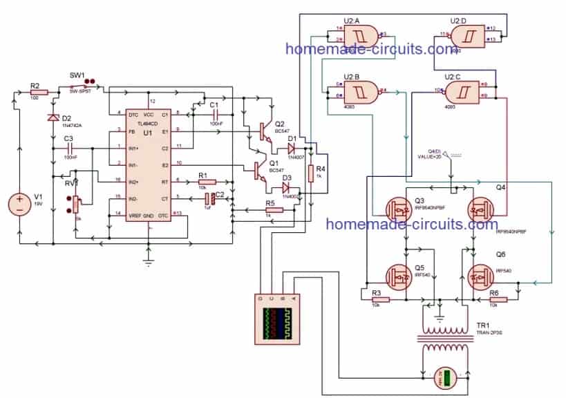
As can be seen, a combination of p channel and n channel mosfets are used for creating the full bridge network, which makes things rather simple and avoids the complex bootstrap capacitor network, which normally become necessary for full bridge inverters having only n channel mosfet.
However incorporating p channel mosfets on the high side and n channel at the low side makes the design prone to shoot-through issue.
To avoid shoot-through a sufficient dead time must be ensured with the IC TL 494, and thus prevent any possibility of this situation.
The IC 4093 gates are use for guaranteeing perfect isolation of the two sides of the full bridge conduction, and correct switching of the transformer primary.
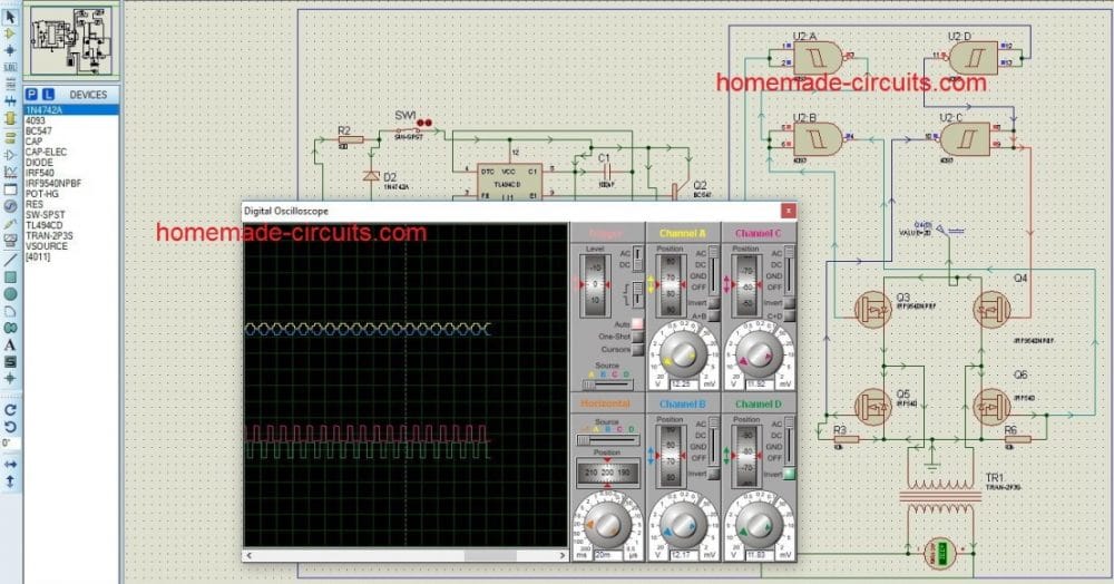
Simulation Results
TL494 Inverter with Feedback
A very simple yet accurate and stable inverter circuit using IC TL494 is shown in the below diagram.
The inverter includes a feedback control system for automatic output voltage correction, applied at the error amplifier pin#1 of the IC.
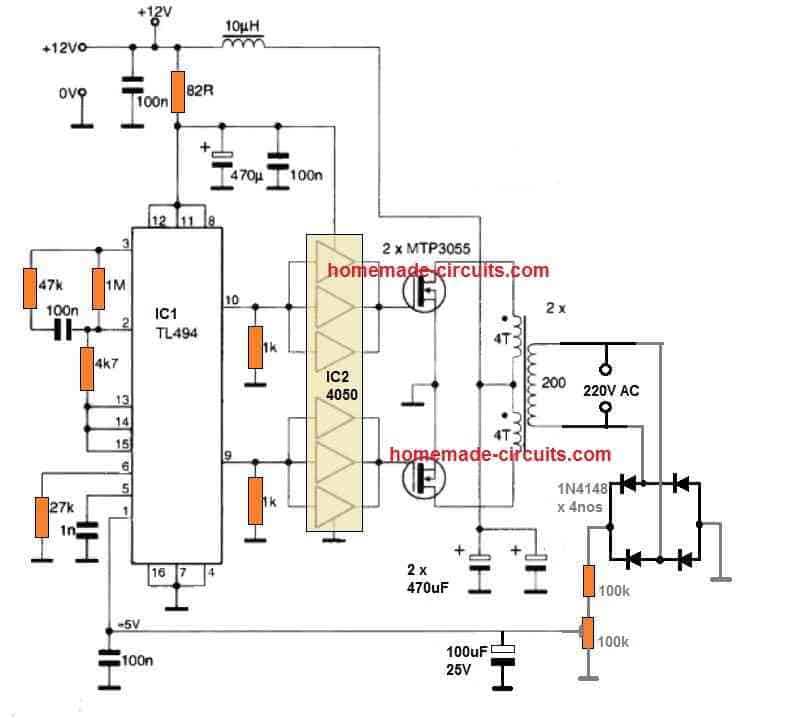
The 100k preset can be adjusted appropriately for setting up the required constant output voltage limit.
The transformer shown is a ferrite core transformer, and therefore the frequency is set at a very high level from the IC. Nevertheless, you can easily use an iron core based transformer and reduce the frequency to 50 Hz or 60 Hz for 120 V output.
Hi, I have built the circuit but get any output from pin 9 and pin 10. what must be the reason, for 50 Hz what must be the trimpot values. I have changed the trimpots from min to max but no output seen. can some one help , will be welcome. thanks a lot
Hi, please check and confirm that the IC supply pins are getting the DC voltage correctly. Pin#8,11,12 must get the +Ve supply and the pin#16,7,4 must get the ground supply.
Also please check the frequency across the pin#5 capacitor.
The formula for calculating frequency is: f = 1 / RT(ohms) x CT(Farads)
RT is the resistor between pin#6 and ground.
CT is the capacitor between pin#5 and ground.
Please what pin should I modify in a TL494 inverter to make to make the low battery 9V. The inverter turns off at 10.5 V but I have a 3S Li-ion battery which can still go as low as 9V.
Thanks.
TL494 can work with voltages as low as 7V, so 9V should not be a problem, you can use this IC with 9V supply also.
Sir, I have a question, Is it possible to generate bipolar pwm signal by using 555 timer ic?? If yes then how to get that
Hello Anupam,
You will have to connect a BC547 transistor with pin#3 of the IC 555, then pin#3 will generate positive PWMs, and the collector of the BC547 will generate the negative PWM
Yes, I made the circuit in simulation software according to what you said earlier but it is oscillating from 0 to positive high voltage. Maybe I am wrong. So, can you provide the circuit diagram or any other documentation for reference.
The output PWMs at pin#3 of 555 will be zero to positive, that cannot be changed. I did not understand your requirement. Please elaborate what exactly you are looking for?
Dear,
Please I have a question, can use TL494 for boost converter from 12 v to 5 v and the vice versa.
Thank you
Yes you can.
please can you provide me one circuit for boost up from 5v to 12v
You can try the following concept:
https://www.homemade-circuits.com/high-power-dc-to-dc-converter-circuit-12-v-to-30-v-variable/
I have other circuits also without using TL494
Con el tl494 no puedes aumentar de 5v a 12 v ya que este circuito requiere mínimo 7.5 v de alimentación
Sir, I have been trying to construct the atx using tl494 or sg3525 with ferrite from old TV’s but it used to burn my MOSFET and i.c, it works but with great heat. My RT and CT are 15k and 0.001(102). How can I solve the problem?
Emmanuel, the ferrite transformer is the main component in any smps circuit. If the transformer is not calculated correctly or has even the slightest amount of incorrect winding then the circuit will suffer and the devices will start getting hot.
Hi sir. I’m searching for a diagram of converter that will able to drive a motor pump about 2000VA or more. The out put is 220V. Thank.
Hi Jean, you can probably try the first design from the following article, and upgrade its mosfets and transformer accordingly:
Make This 1KVA (1000 watts) Pure Sine Wave Inverter Circuit
This is an easy and cheap design so the efficiency will be only around 70%
Hi sir. Thanks for quick answer, I’l try it
Sure! no problem…
Thank you for prompt response. Please, Can ferrite transformer high frequency inverter be used to safely power some equipment at home at KHz frequency?
Are there KHz frequency final output inverter in the market?
Can KA7500 or TL494 ic actually generate 50 or 60 Hz frequency(datasheets stated KHz) or how can frequencies of 50 or 60Hz be actually generated from the ic?
Actually the TL494 cannot generate 50 Hz, the minimum is 1 kHz. You can perhaps use a inductive/capacitive filter at the transformer output to clean the high frequency waveform and convert it to normal AC waveform.
You stated that ferrite core transformer can be used. What frequency would the ferrite operate in the inverter. Ferrite core transformer operates at high frequency(KHz) while iron core transformer operates at low frequency(50 or 60Hz) which is the main frequency. The frequency to operate ferrite core transformer is too high for main ac and ac motor etc can not work well at that frequency. Also Can KA7500 or TL494 ic generate 50 or 60Hz wave(datasheets state KHz). Thanks
If ferrite core is used then naturally the frequency cannot be in Hz, it will need to be increased in many kHz
Hi sir, want to build up a inverter using pic as the controller.please,can you give me an article on how to get started on pic controller coding and the ?pin out
Hi Eniola,
you can modify the following circuit as per your specific requirements
https://www.homemade-circuits.com/arduino-pure-sine-wave-inverter-circuit/
Sir,in the first circuit diagram, can I connect the feedback to pin 2 and pin3?since,pin2 is the inverting pin.
John, pin#3 is not the correct pin, you must select one of the error amp inputs. Please see the last diagram.
Hi sir, according to your first circuit diagram, you taped voltage from pin 14 to pin 1, what if I fixed it and compare it with pin 2 from the feedback voltage.because, I’m thinking of feeding pin 2 with feedback (non inverting pin) in order to stabilize the output.but, the last circuit diagram shows that pin 1is feed from feedback voltage and pin 2 is a fixed voltage feed from reference voltage (pin 14), but to my knowledge when the output is high obviously the comparator won’t low,it will also be high.but if the feedback voltage is feed to pin 2 it will obviously oppose the output.i I mean when high the comparator Will be low trying to stabilize the output.waiting for your quick response.thanks sir
Eniola, the last diagram with feedback is correct. Pin#2 is an inverting input. The inverting input (-) must be connected to a fixed reference, and the non-inverting (+) must be applied with the feedback signal. The error comparator output must become high to enable output PWM narrowing and output voltage control
Thanks sir,got the message.one more thing sir, can I then connect pin 2 and pin 3 to pin14 ?if yes at what voltage can I I supply them? And finally resistor value for dropping the voltage.thanks sir, looking forward to your quick response.
Eniola, you must do exactly as shown in the diagrams, any other configuration can cause unpredictable results
Sir, to protect the mosfet from emf voltage.the resistor value for discharge to ground and diode? Thanks sir
The resistor can be 1K across gate/source for 12V….10 ohms for the gate resistor, and 1N4148 parallel to the 10 ohms
Or just tell me how pin 1 correct the output.thanks sir looking forward to your quick response
Okay,I gave pin 1 feedback and pin 2.5v from pin14 using two 5ohm resistors.but, how can I connect pin 3 with pin2? And the resistor value?
Please see the last diagram for all the details.
Sir, the 1k resistors in the above circuit diagram,I think it should be connected to gate and source of the mosfet so as to make easy discharge of the mosfet capacitance, Or is it ok as it is.please sir I need quick response from you.thanks sir
Eniola, the indicated 1K positions are correct, however you can additionally connect them across the gate source of the MOSFETs, although it is not required because the PNP transistors are enough for executing perfect gate discharge during the low signals
Please sir,I want to wind up a iron core transformer for inverter at 9v primary and 220v secondary, but, for the turns ratio i don’t know the actual winding.please, can you just give me a link? Thanks sir
Hello Eniola, you can read the following artcles for all the required info:
https://www.homemade-circuits.com/how-to-design-your-own-inverter/
https://www.homemade-circuits.com/how-transformers-work/
https://www.homemade-circuits.com/how-to-make-transformers/
Hi Swagatam,
Can I use TL494 in an Inductorless sign wave inverter?
Can the output wave amplitude be varied from 0 to the maximum?
My supply voltage can be 17Vdc or any required voltage to produce a 12volt RMS ac
Hi Kazem, it is not possible to make a variable supply from 17 V to 12V using PWM, because although the average voltage may decrease to 12 V but the peak voltage of each pwm pulses will be always 17 V. You can vary from 0 to maximum, but peak voltage of each of the pulses will be always 17 V which can harm the connected load.
swagatham g i want 12vdc to 50vdc boost converter ckt diagram o/p current 10amp.
Sreenivasulu, you can try the boost converter design from the following article:
DC to DC Converter Circuits using SG3524 [Buck, Boost Designs]
Can you explain to me how do you get 10 windings of 4mm enameled wire into an EE container for transformer and then another 200/300 of 0.5mm wire? Either you’re wizards, or you’re kidding me! Third option, you made some apps do the math and then you threw a container there at random ….
Can you explain, why do you think I am a wizard?
If you Don’t like this data? you can feel free to calculate it from the following articles:
How to Calculate Ferrite Core Transformers
How to Design a Flyback Converter – Comprehensive Tutorial
Hi Swagatam,
Thanks as always for this awesome inverter design. I am making the ferrite transformer myself. I am just a hobbyist, so I need a little more info on it.
I’ve got a ETD42 Ferrite. Please let me know which SWG numbers (or diameters) of wire and how many turns should be good for primary and secondary and if any specific instruction on how to wind (direction etc).
I want to get 150-200 watt of power at the output, I will add up more Mosfets to boost input power. But please let me know what would be the specs for the copper wires.
Thank you Prithwiraj, I appreciate your interest! However, designing a ferrite based transformer can be complex, and may need some serious calculations. I have explained the details in the following article, which you can refer to:
How to Calculate Ferrite Core Transformers
Nevertheless, if you want to do it with some trial and error method, then you can probably try the last circuit from this article:
https://www.homemade-circuits.com/half-bridge-mosfet-driver-ic-irs21531d/
Good Day sir. Is it fine to add feedback circuit (consisting diode, resistor & trimmer). If its fine, Im planning to connect it to the pins 2 & 3. Love to hear your response as soon as possible.
Yes that’s possible…you can find an example design here
https://www.homemade-circuits.com/5v-pwm-solar-battery-charger-circuit/
Hello sir, thanks for the wonderful circuit, i have a question to ask:
1.i have mosfet irf1404, can i replace it with the mosfet in the circuit?
2. What is the appropriate resistor to connect at the of irf1404 mosfet?
3 how can we set the pwm
Solomon, Please check the VDS (max drain voltage) and ID (max drain current) of the MOSFET from the datasheet this will give you an idea regarding its maximm capacity and whether it is capable of handling the required load or not.
resistor will be same for all mosfets.
Adjust PWM by checking the output voltage… until you get the correct RMS output
Thank you sir, much appreciating
Just thinking out loud , I’m sure you have already done it but at the primary side of the ‘12 – 0 – 12 ‘ {example}
If one connected a half bridge type reasonably fast diode from each ‘12’ back to the ‘0’ so that when each switch occurred in the ‘on’ state it would not conduct but when each ‘12’ leg is in the ‘off’ state when the polarity reversed then in this case that reversed polarity would be returned to the source {in this case the battery}
I can’t add a pic but I’m sure you see what I’m saying ?
Thanks again
Regards
Yes freewheeling diodes are definitely recommended across the transformer center tap primary winding, to safeguard the MOSFETs although nowadays MOSFETs already have these diodes in-built.
Hmm interesting thanks for the reply
But isn’t it correct that any diode in a MOSFET can only be from the ‘source’ to ‘drain’ in the case I’ve outlined here I’m Picturing a diode from the transformer primary out back to the 0 or ‘center tap’
This would theoretically direct any reverse polarity back to the source ‘the battery’ I just built this circuit but haven’t tested it to the degree where I can say what polarity shift takes place, but i put in place the diode bridge and nothing exploded {yet} so I’m up for today.
Regards
The cathode of the diode will connect with the outer taps of the transformer, while the anode of the diode will connect with the center tap, this will quickly short circuit the back emfs from the winding, and will not send it to the battery.
– ‘Cathodes’ of half bridge to center tap ‘positive’
– ‘Anodes’ to outer taps.
If / when the polarity reverses in a dead time of PWM it would underline possibly, rectify back to battery.
That’s what I did, I haven’t been able to check the function as of yet but nothing is getting hot or melting.
Regards
If that happens, it will help to get the battery charged a little, so no problem with that.
Hi sir, please my requestion on the ic TL494 pin and pin 10 pls I want to know the voltage comes from them to the Gate of the mosfet. Thank you
Hi Saeed, the average DC on these pins will be half of the supply voltage provided the duty cycle is 50%. If you reduce the duty or the PWM to a lower value then the output will be less than 50% of the supply level.
Hey just want to reach out and say thank you for sharing, great explanation, and a very helpful design with specifics relating to this being both a Astable and PWM control .
Again thank you.
Regards
Thanks for liking the post, appreciate your feedback!
Halo sir, thanks for sharing.
I want to design a wireless power transfer device. and I want to use the inverter circuit that you have shared. specification: Frequency of 70 khz, to produce sawtooth waves Transformer = 12 v proportional to battery voltage. for TX and RX I use 2 different types of coils. I want to ask, how to connect the LC resonance circuit? Is it after the output of the transformer? Please help. thanks
Hello Anas, sorry I am not sure to you can get sawtooth from this inverter and why? Please elaborate!
Hello,
You have not mentioned about the sine wave which will be compared with saw tooth internally produced by TL494 IC. I would like to know if there is sine wave produced inside the IC and if so, how it’s frequency is determined.
One more thing, how do we determine amplitutes of triangular and sine wave if both are produced internally.
I have read your datasheet about TL494 but could not find answers to my question.
Thank you in advance!
Hello ,
the sinewave must be generated externally using a IC 555 oscillator and an integrator. The triangle wave from the TL494 and the sine wave from the 555 will go to the inputs of an external op amp which will then process these two to produce the required SPWMs. The frequency of the SPWM cycles will be controlled or synchronized by the triangle wave frequency from the TL494, while the number of voltage blocks in each SPWM cycle will be determined by the IC 555 frequency.
Hello swagatam I have not seen any circuit diagram in this article pls I would have love to view it
Hi Emmanuel, there are altogether 3 diagrams on this page which I can see in my computer, please check it again by refreshing your page or may be in another browser, are you using chrome? Please let me know if you see them.
Alright I can view it now
Thanks for the feedback!
Hi Swag. Could you please tell me which circuit simulator did you use? Thank you very much!
Hi Marco, actually the last two diagrams were sent to me by one of avid readers of blog, so i am not sure which simulator he might have used.
can this deliver up to 2500watts… the circuit seems easy but i wonder if i will fine TL494 in my area.
that’s possible with any inverter design, simply by modifying the mosfets, transformer and the battery
https://www.homemade-circuits.com/how-to-calculate-and-match-inverter/
Ok sir.
I got the parts like lucky, but what if i increase the amount of mosfets IFR540 And also change the size of the transformer, i guess i will be running the circuits now with 24VDC not 12VDC again, but if 12VDC can give me up to 2500watts i will be happy to do it that way because i will use two batteries in paralel.
I wait your advice.
If you use 12V, the current requirement will be approximately 2500/12 = 208 amps, with 24V it will be 50% less.
Hi
I built your circuit and connected it to a 40 Watt 0-7.5-0 transformer and I have 3 issues with this circuit now :
issue1) When I connect my laptop adapter, the output frequency is distort, and a hammering sound starts from Transformer. The re is no effect if I try to compensate with frequency Pot; only the tone of the sound changes.
issue2) The output voltage is changed if I connect different loads, and for every load, ex. lamp or charger, one should proceed to correcting with PWM Pot every time.
issue3) When I try to parallel Mosfet output stages with the same Mosfet configuration, the no- load current increases and Mosfets get hot, and I cannot increase the wattage of the circuit. How can I increase wattage?
Thank You.
Hi, please check the frequency that you are getting from the output of the transformer, it must not be high.
secondly I could not understand your transformer rating? what does 0-7.5-0 mean? I could not get it.
The transformer rating, the frequency and the load current must all be compatible with each for the proper functioning of any inverter, make sure these are all correctly selected.
I meant this type of a metal-core transformer : 7.5-0-7.5 in primary and 220 at secondary . Sorry that I made mistake when writing its specifications last time.
Also, in frequency section of the circuit, The only difference with your posted circuit is that I put 33k resistor between pin 6 of TL494 and ground instead of potentiometer and 4.7k in your posted circuit; all other capacitors and resistors are same as your posted circuit.
The laptop AC adapter is ASUS model : ADP-65GD B : input AC100-240V 50-60Hz 1.5 A & output : +19v DC 3.42A.
I do not have frequency meter, but clearly there is a sound difference when I connect this ASUS laptop computer adapter . and I repeat for you my 3 issues here:
issue1) When I connect my laptop adapter, the output frequency is distort, and a hammering sound starts from Transformer. The re is no effect if I try to compensate with frequency Pot; only the tone of the sound changes.
issue2) The output voltage is changed if I connect different loads, and for every load, ex. lamp or charger, one should proceed to correcting with PWM Pot every time.
issue3) When I try to parallel Mosfet output stages with the same Mosfet configuration, the no- load current increases and Mosfets get hot, and I cannot increase the wattage of the circuit. How can I increase wattage?
What is your transformers current rating and battery Ah rating?
You must check the results with a 100 watt bulb first, makes sure it illuminates smoothly.
Frequency is very important, you will have to check and make sure it is within 50Hz if the transformer is an iron, however a TL494 may not allow you to reduce the frequency below 1kHz…as per the datasheet.
power can be increased by increasing the transformer, battery and mosfet rating together.
I checked with 3 lamps totally around 100 watts and I gained exact 220V AC across them with no drop -down of voltage while my voltmeter shows 336 VAC at no-load.
The AH of the battery is 65AH ; a new typical car battery, no problem with that.
The transformer is a 40Watt 7.5-0-7.5 to 220 with a iron core size of 6.5cm-3.5sm.
Is it good to make an increase in number of Mosfets with a 100 ohm resistor connected to EACH gate of a single 100 ohm resistor for all mosfets is enough? can you put the suitable circuit showing how to increase the number of mosfets?
or any suitable LC filter at the output to stop the hammering sound when I connect this Laptop adapter to the output?
Thank you.
Power handling capacity can be increased by putting mosfets in parallel but here it won’t be useful, because your transformer is 40 watt, single mosfets would be enough to handle that much power.
You can think about increasing mosfets numbers only if your transformer is rated at 300 watts or 500 watts.
I think instead of TL494 you should try some other inverter circuit such as using 4047 or using transistors.
and if possible use a 12-0-12V transformer if the PWM function is not being used, that will give you around 220V output, the hammering sound could be due to high voltage from the transformer.
The operating of TL494 is I Khz to 100 kHz so , the frequency you obtain is obviously high and hence its humming
Sir can i connect 13,14,15 pin of ic to ground using 10k resistor?
So that i can use pin1 of ic for output correction
Loki, if you do that your circuit will stop working and mosfets will burn.
The circuit shown is correctly configured and nothing needs to be changed in it
for feedback control you can connect pin#1 with the output through a suitable resistive potential divided network, as show in the following example:
https://www.homemade-circuits.com/5v-pwm-solar-battery-charger-circuit/
Hie Sir
As for the feedback, how to calculate resistance of resistor divider network
Hi Thatcher, you can take the help of the following software
https://www.homemade-circuits.com/voltage-divider-calculator-software-potential-divider-calculator/
How can i fix the voltage drop issue please help me
I dont have 4. 7 ohm resistor can you please tell me the equivalent one
use 10 ohm or 20 any resistor below 33 ohm will do
Hie Sir.
Can you please help me with a complete schematic of the driver stage intergrated with bootstrap for high side switching that will drive h-bridge instead of this half bridge. I intend to use it with tl494 modulations ,the h bridge will be connected to 380vdc.
Hi Francis,
you can refer to this article, and try to implement the same in your TL494 circuit
https://www.homemade-circuits.com/sg3525-full-bridge-inverter-circuit/
greetings
I want to wind a transformer using the core area and ferrite core with 12vx2 input and 11v output with the frequency of 1.2khz.
can you please show me how did you compute for the sizes of magnet wire and the number of turns
sorry, I have no idea regarding the calculations of the inductor…this design was taken from the datasheet of the IC ready made. You can perhaps give it a try through some trial and error…
Can i avoid bc547 and bc557 transistor and directly connect the outpit of ic to mosfet
if you are not using pwm feed then you can do that….
please i need 12vdc to 320v dc boost coverter using TL494 its urgent please.. i want to use it to make smps inverter.
I’ll try to design it if possible…
Hi sir, you mentioned an how to use ferrite core, pertaining number of turn but you didn’t say about switching frequency, will it work the same with 50 or 60Hz?
Raymond, with a ferrite core, the frequency will need to be around 20 to 50kHz
Does this circuit requires oscilloscope for frequency adjust?
oscilloscope is mainly used for verifying waveform, frequency can be verified using any DMM with frequency range.
But I don’t have dmm can you give me the resistance value for 50 or 60 hz which I can use instead of potentiometer
without a DMM you cannot start with any circuit, you will have to buy it first for any circuit related project, and make sure it has a frequency measuring facility.
I have calculated the value of capacitor and resistance using an online calculator as you can see in the image in the link https://drive.google.com/file/d/0Bzt8mctLFz_6MDFPUGZSZWY4alk/view?usp=drivesdk can I replace the 220nf capacitor with this capacitance value?
I am not sure whether it is correct or not…you will have to verify it practically.
Hi! Thanks for your post
Do you have any other information that could help understand this circuit with more detail?
Hi, I’m glad you liked it!
you can refer to the datasheet of the IC for understanding the concept with greater depth:
http://www.ti.com/lit/ds/symlink/tl494.pdf
or if you have any specific questions you can ask them, I’ll try to solve!
hi swagatam,
it is possible to add such a protection circuit to detect if any short circuit on the secondary (220V) side , possibly add a relay to protect the mosfet ?
I am going to build these with 8pairs of mosfet IRFZ44N to drive the iron cored trafo.
Any advice really appreciate
thank you
Hi dedy,
you can try the concept explained in the following article:
https://www.homemade-circuits.com/2014/06/simple-current-sensor-circuit-modules.html
use the NPN version, and connect the collector with the mosfet gates via separate diodes or simply connect it with the “Ct” of the IC,…. for SG3525 you can use the PNP version, and connect the collector with pin#10 via a 1N4148 diode
Thank you Swag,
I’ll be using TL494 IC so what I Need to do is using the NPN version of Current Sensor and connect the collector of TR BC547(NPN) to the TL494 pin 5 (ct) am I right ?
yes that’s right dedy, do it exactly in that way
Hii ,, I am going to build these circuit but curious if it can be added such a protection circuit with these IC ?
Hi, what kind of protection do you want?
please upgrade thi cct for 500w out put.
give us the power circuit for 500 w out put
thanks
you just need to upgrade the trafo wattage, mosfets specs, and the battery AH for getting any desired output as per your requirement…
Hi Once again Swag,
i built this circuit every thing works fine but the frequncy is not stable it keep fluctuating up and down
Thanks Ferdimar, you can try using a 7812 regulator for powering the IC with a stabilized voltage, and also replace the frequency adjustment preset with an equivalent fixed resistor.
THanks for the quick respond,
i already with the power stage of this 48v inverter circuit https://www.homemade-circuits.com/2014/11/48-v-inverter-circuit.html
with the BC546 and fixed a 150k resistor at the frequency and also tried two different IC747 but still can figure out the cause.
any other suggestions might help again
thanks.
BC546 emitter follower example will not be stable enough, still you can try connecting a 12V zener at its base/ground with a 100uF cap parallel with the zener.
If still it does not stabilize then you may have opt for some other more reliable regulator which can work with 60V or higher supplies.
thanks much Swag.
i figured it out, was the cause of my pwm control pot,replaced and it working fine now with the BC546 which is stable now.
am now trying to use this IC494 to make a full hbridge since i dont have this IRS2453.
i know your much busy but hope you one day make full hbridge circuit for this.
thanks once again for your support.
that's great ferdimar…thanks for updating
yes I will definitely post one H-bridge design, but not with TL, rather with an SG3525 which can be easily applied for the TL494 also…
okay will find out from the store if i could get my hand on SG3525 whiles i work with TL494 H-bridge for now and await for the design.
Stay Blessed Swag.
you are most welcome!!
The transformer that you have mentioned is having 400 turns ratio.Considering 230v at secondary,primary will be less than a Volt. Am I making a mistake ? Pls guide.
sorry it seems to be a typo, it should be actually 200 turns and not 2000, I'll correct it soon
You have mentioned in the design that for compact design iron core can be replaced with ferrite core.My question is ferrite core is used with high frequency & iron core is used for lower frequency. How without making any changes in the design iron core can be replaced with ferrite core ?
obviously you will have to use high frequency for a ferrite trafo, that's an understood fact, I might have not mentioned it because it's not the main subject of the article, I have only given a optional suggestion.
…it could be done by increasing the value of either Rt, or Ct proportionately.
Dear Kaustav, I got the diagram from another site, it's not my design
The "recommended" minimum oscillator frequency (not PWM) is 1kHz, but you can try reducing it upto 100Hz….if it doesn't work normally then you could probably try a SG3525 based designs which has exactly the same features without restrictions.
hai boss
when i adjust pwm pot suddnly out put gone and one mosfet burnt
also i try three times to add two fets but failled.
now i m going to add two fets again by connecting two gates together and gives one gate signel both
using one resister
.what will happen
Hi Upul, the mosfet should be attached very close to the BJT stage, mosfets can burn due to many strange reasons, as I have explained below
https://www.homemade-circuits.com/2013/09/mosfet-protection-basics-explained-is.html
moreover mosfets should be used only in well designed PCBs and not on breadboards.
if adjusting the PWM is causing issues, I would recommend that you connect the mosfet after the adjustments are completed, and keep it disconnected while you are doing the adjustments.
Any other method may not be so effective.
Hello,
Really helpful post. Can I use this circuit for high frequency inverter (110V, 800 HZ). Should I use a high frequency transformer for it. Please suggest required changes if any.
Thank you.
yes you can use it for the mentioned frequency, for 800Hz a laminated iron core will work, no need for a ferrite core transformer.
except the frequency all can be exactly as shown
hello
we cannot add more mofets in parallea to this mosfet driver part.all bjt get burnt and fets also burnt
.so this cannot upgrade for higher wattages.
i connect two mosfets to driver cct using two 4.7 resisters.
but all bjt burnt /mosfets burnt /ic burnt
No that's incorrect!!
the BJT stage cannot get loaded or affected due to a mosfet because mosfet gates have a very high resistance, and on the other hand the BJTs cannot impact the gates of the mosfets again because of the high resistance of the mosfet gates
your mosfet could be getting damaged due to some other reason.
and mosfets in parallel can definitely be added with the shown BC547/BC557 stages.
instead of irf540 can replace with transistor like 2n3055 or 2n2955? please reply asap
you can use them, and in that case the BC547/BC557 can be eliminated, and their bases can be directly connected with the IC output pins….through a Darlington BJT stage.
let it say the BC547 and Bc557 are still intact without any modification.. but all i asking if is it OKAY to replace the IRF540 into 2n3055 or TIP3055…
thanks.. for now i am making layout.. replace reply asap thanks
No it won't work, unless you do the above mentioned modification
thank you for your response sir
and this is your original schematic
I made the layout
?oh=1eb409ed60856f61b46dd6a8a978563e&oe=5831C41E" rel="nofollow ugc"> ?oh=1eb409ed60856f61b46dd6a8a978563e&oe=5831C41E
may I ask sir what best mosfet to put on your circuit not lessthan 50 amperes. the size should likely IRFP064N
what best mosfet so I can buy in our Local market
THANKS
You can try STP60NF06 mosfet which looks most suitable for your application…PCB looks good, though I could not check it thoroughly
thanks sir
why mosfets damage when i connect 200 va transformer after few minutes. does it need to add resisters to gate and source.
also does it need diodes to prevent back emf.
It is not absolutely necessary to add resistor across gate and source but you can try it if you wish…the mosfet must be positioned as close as possible to the BJT buffer stage.
yes diodes could be crucial and is recommended across the source and drain of the fets.
i adjust 10 k pot
now both sides working
now i want to improve wattage of this cct
how can i connect more fet s.
to increase waattage either you can use high current rated mosfets such as this
https://www.homemade-circuits.com/2013/05/high-current-mosfet-irfp2907-for-wind.html
or use mosfets in parallel having modest current rating
thank you sir
can i parallel another same mosfet to this drive terminal
without adding other transisters
yes you can do that
thank you for reply. i made this cct and it works well two times .but after i put another mosfet in parell.then all transisters damage .after remove mosfet the cct not working now.
i replace transisters and ic .but now pin 9 output only occilating .pin 10 line not working.
how to correct this.
It will be difficult to judge the fault without a practical viewing, I would suggest you to build it afresh over a well designed PCB and with a IC socket for the IC…and then see how things go!
thank you
ic was the problem
i change ic and adjust 10k now ok
Hi Swagatam,
I am doing a project where I need to generate a pwm signal for a 35 V DC input using TL494. The output should be a wpm signal of same voltage. Can you please tell me how to use it to get a pwm signal? I have been stuck on this problem for quite some time now.
Hi Shuvam,
you can use the following circuit with some modifications:
https://www.homemade-circuits.com/2015/05/5v-pwm-solar-battery-charger-circuit.html
remove Q1, Q2, R12 and the associated inductor and the diode.
replace R10 with a 10k resistor, attach a NPN transistor with this resistor, with its emitter to ground and the collector to positive via another 10k resistor.
also replace R8 with 1K resistor and R9 with 10k pot, now altering this pot will produce a varying PWM at the collector of the NPN
Thank you for you help. I am planning to use this to control the brightness of an arrangement of led lights which operate in normal mode at 0.35 A and 35V, which comes to 12W. Is there any further things I should be careful about to avoid damage to the light?
you can include a current controller stage in the middle to ensure the LEDs operate safely during the full duty cycles.
you can refer the following article for this:
https://www.homemade-circuits.com/2011/12/make-hundred-watt-led-floodlight.html
I am slightly confused about the transistor connections. The base is connected to 10k resistor, emitter to ground and collector to + output terminal?
which diagram are you referring to?
There's no 10K in the above linked diagram, it needs to be calculated
2.bp.blogspot.com/-wrDlwFwtTZ4/Ub_cByhgJYI/AAAAAAAAEeM/C78ehqAubS8/s1600/100+watt+led+driver+circuit.png
Hi Swagatam,
I am doing a project where I need to generate a pwm signal for a 35 V DC input using TL494. The output should be a wpm signal of same voltage. Can you please tell me how to use it to get a pwm signal? I know the question is completely off the topic but I have been stuck on this problem for quite some time now.
SIR,
I HAVE 230V/12V-0-12V IRON CORE TRANSFORMER.CAN I USE THAT.
ALSO WHERE IS THE 22K POT IN CCT .HERE HAVE 10K AND 100K ONLY
Upul, yes you can use the mentioned transformer, actually it's a 100K preset not a 22k
Sir, Can you please explain the purpose of pin no 8 and 11 .
Although it's a nice article .
Thanks Kartik, although I had studied it earlier I do not remember it now, please refer to the datasheet of the IC you will immediately get the idea regarding it.
you may also refer to this article for the same:
https://www.homemade-circuits.com/2015/05/5v-pwm-solar-battery-charger-circuit.html
Ur circuit schematic working well on my bread board – thanks . I used a old 15v-0V-15V transformer removed from a old dead UPS thus i got 150V – 160V from a 12V, 2A battery. Tried and failed to shut TL494 down like her close relatives – SG3524/3525.. Perhaps i concentrated my experiment on Pin 4….. I got one IC damaged already… Please do u have any idea or suggestion how i could shut TL494 oscillation down??….Please u can reply me here or via sammytrench@yahoo.com
Samuel, try grounding pin#1 that will almost shut down the IC.
By the way the trafo rating must be always lower than the battery voltage for acquiring the correct optimal output voltage level.
I intend to use a 9V linear voltage regulating circuit with shut down and Soft start to power TL494… Since these two fixture are lacking in 494…
OK??…
sorry I have no idea about it…..
Hello Mr.Swagatam,ahmad from Indonesia I'm sorry if my english is very ugly I hope you can understand my situation, I have some questions:
1. whether the value of the capacitor on pin 5 it can be replaced, because I had trouble getting capacitor with a value 220nf
2. whether veriabel resistor on pin 6 (100k) and pin 1 (10k) it needs to be played back or regulated, how.
Thank you very much
Hello Ningrat,
you can try some other closer value for 220nF or use two 100nF (0.1uF) in parallel
I have explained the control and calibration procedure in the article, please go through it carefully
Hi looks so simple.i want to use a ups transformer without center tap.how cn i eliminate d center tap n stl use dis same circuit tnx
Hi, sorry you cannot use the above circuit without a center tap trafo, it may be possible but could make the circuit much complex
instead you can try full bridge driver IC for operating a transformer without a center tap.
Hi Mr.Swagatam
Thanks for your sharings. is it possible to modify this circuit for 14.8v dc input to 220v/ 110v ac output?
Thanks
Hi AD,
the above circuit is designed to work with a 14V supply, the output will depend on the winding rating of the trafo…could be 220V or 110V
i made this inverter exactly the way you designed it and it worked. I used it to power 100w bulb. I used a ferrite transformer i found in my damaged Chinese 12v 1000w compact inverter, though it was labelled 1000w but I doubt. Now, I want you to help me increase it to 36v 2000w. I know that the IC will be fed with 12v, I will use 7812 and 7824 regulators ic to regulate 36v to 12v for the circuit. What will be the turns of the ferrite transformer for 2000w? if i want to use a high frequency, i know that i have to select rt/ct network to obtain the high frequency. i want to know the frequency suitable for a 36v 2000w compact inverter using a ferrite transformer? Thanks
you can try by the rule of thumb and use 15 + 15 turns for the primary, and 330 turns at the secondary.
primary wire could be 2 mm thick, and the secondary 0.5mm
frequency could be anywhere around 20 to 50kHz, check by trial and error which gives the optimal response….use EE core for the transformer
Hi,
Great web site and you must be very busy with all these circuits.
I have what maybe a dumb question, when you say "primary configuration of
9-0-9V" for the sine wave PWM inverter, do you mean 9 turns to center tap?
I see you have 9V there, does that mean 9Volts? Or a transformer which would
be 9V if you were to connect 220vac to the secondary as if it were the primary
in a step down application?
Thanks!
Marc
Hi, thanks
It means that the primary should be rated at 9V-0-9V with reference to the 220V secondary.
yes that's right if 220V was supplied at the 220V side that's supposed to generate a 9V-0-9V across the other side.
Hello Sir!
Can I use a 48 Volt battery system here?
And is it a way to use a transformer without CT?
(hard to come by, that will fit the 48V, 20-0-20?)
Using one P-ch, one N-ch MOSFET. Maybe in pair's like in this:
https://www.homemade-circuits.com/2012/05/make-this-1kva-1000-watts-pure-sine.html
I find a lot of interesting things here,
Thank You.
Thanks baron,
yes you can use the design for 48V operation, just make sure the IC section is operated with a 12V stabilized supply, which can be easily implemented using an emitter follower transistor stage….you may refer to the following article and see how the BC546 is configured for the same.
https://www.homemade-circuits.com/2014/11/48-v-inverter-circuit.html
for eliminating the CT, you can incorporate the following design:
https://www.homemade-circuits.com/2014/01/simplest-full-bridge-inverter-circuit.html
the load is your trafo primary….and the AC rectified line may be replaced with 48V or the desired battery voltage.
Hi Swagatam,
I'm testing this circuit on breadboard. I'm using the same values as you have mentioned. I'm using a 12-0-12 10A transformer. When I check the output voltage, it's in the range of 300v. Adjusting PWM control has no effect in the output voltage. The output frequency is about 35KHz (checked after stepping down). When I adjust the frequency pot, it reduces a little. but not much. Shouldn't the frequency read in the range of 40 – 80Hz? Why it reads 35KHz?
When I look at the datasheet, I see that this is the formula for Frequency.
Single-ended applications:
f = 1/Rt*Ct
Push-Pull applications
f = 1/2Rt*Ct
I believe this is a push pull application and if we use the second formula with the values you have given:
1/2*15000*.000000001 = 33333Hz.
This is the frequency I measure after stepping down the output.
But if I make these changes according to the formula:
F = 1/2*45000*.00000022 ~ 50Hz. (100K VR set to ~45K and a 220nf). With these changes, I get correct 50Hz. Now my multimeter measures 250v but I'm still not able to adjust the voltage using the PWM pot. Should I add a feedback from the output?
please let me know if what I'm doing is correct.
Thanks,
Vijay
Hi Vijay,
the PWM pot is referenced to ground, please check whether you have connected the ground with the PWM pot or not, otherwise it will not work.
after connecting make sure the pin#1 voltage changes when this preset is adjusted….this is supposed to change the reference voltage for the error amp which in turn is supposed to narrow or widen the PWMs
or simply short the pin#1 with ground and see the response.
I'll the frequency components values in the diagram soon.
Hello Vijay, have you done the adjustment as posted by Swagatam? Please let's know the result.
very impressive circuit, its working on high freq. 16khz and low freq. 60hz. the only problem here is the pwm control, yes we can adjust the voltages in fix value. but when the source voltage up let say 12v to 15v the output voltages also increases. unlike my current pwm squarewave sg3524 has a perfect voltage control even we use 12v-24v supply the output voltage remain steady. sorry for my bad english, i will appreciate if our master fix or correct the pwm section thank you. God Bless!
OK thank you very much, in that case I'll request you to check the two designs and find out the what may be causing the two designs to work in slightly different ways, because I have configured he pinouts as per the datasheet of the IC and exactly as per the pinout functions of the IC.
By the way the above circuit does not include an output voltage correction circuit stage…that's an external ad-on circuit which may be required for controlling the output voltage, and may be that is why the above circuit is not controlling the output voltage.
my bad i though this design got output voltage controller. sorry for my comment earlier, pls help us to attach the voltage controller on pin 1. theres another question i would like you to know, why when we use the push pull transistor the transformer generate to much noise, yeah the gate voltage become high if we use push pull transistor but the waveform on oscilloscope become too small? my testing design none transistor.
you can refer to the following article and use it for the required application:
https://www.homemade-circuits.com/2014/01/automatic-output-voltage-regulator.html
remove the transistor collector diodes, and connect the collector directly with pin1
sir we design the above circuit but its not work. Actually I can't understand the working of the circuit. I have many troubleshooting problem. Kindly mention the working of the circuit..
Thank you
what frequency are you getting at the pin9 and pin10??
…I have already explained everything comprehensively in the article, if you have any specific questions, you can put them here.
Hi Mr. swagattam can i use IRF 3205 instead of the mosfet above and a Microwave Oven Transformer with its secondary removed and rewired using 10 gauge wire centre tap?
Mr. mach3z, yes you can use the mentioned mosfet.
the entire trafo prim+sec+size will need to be appropriately dimensioned for the specified load
Hi sir Swagatam, I want to ask one question; Sir, to 50hz what fixed resistor (RT) is needed instead of 22k pot.
Hi clickbirth, I have not yet researched this parameter so I have not idea about the formula for this, alternatively you can test it by adjusting the 22k pot and then verify the resistance value across the pot for determining the value
Hello Mr. swagatam I want to do this one again I have bought all the requirements now but I want to know how many volt and ahms transformer should I use to get 300watt or 500watt? Thank you sir.
If your battery is 12V then the trafo will need to be 500/12 = 41 amps ans 9-0-9V
battery will to be at least 100 AH
So basically sir what this means is that
1)the 10k pot can be used to adjust the output voltage.
2)even the modified sine wave inverters that employs the SG3524/SG3525 chip or even ur own SG3525 modified sine wave circuit you posted on your site earlier can eliminate the feedback transformer from the output inverter itself and all that rectification and all that will be eliminated and we can rig the SG3525 to work without all those diode rectication and the small feedback trafo,exactly in the same way the TL494 works in maintaining constant voltage under varying load conditions.?
By the way it's Michael not Alex.
That's right Michael.
Because, according to me as long as the 5.1V reference stays constant the PWM would also stay constant which in turn would make sure that the outputs voltage stays constant.
so yes even for SG3524/3525, the principle of operation looks alike and therefore an external feedback may not be required for the corrections.
sorry for the confusion, your questions are much identical to what Mr. Alex (another dedicated member) normally asks,,,that's why I mistakenly thought you to be him.
Sir does this mean the inverter does not need feedback from the output of the inverter.?
Does it mean that if it is a 1500w or 5000w inverter rated at 220v operating at full load it will regulate it self to steady 220v who operating at full load?
Mr Alex, that's correct, because the PWM is set by referring to a constant 5V generated at pin14 of the IC, once set, the PWMs will not change regardless of the output load, unless the load spec is too high and the reference 5V is disturbed due to a alarming drop in the battery voltage
hello janak,
the IC already has an internal oscillator, no external pulse is required here.
and yes without a frequency the fets will stall and instantly burn, a frequency is the only way to keep the inverter and the fets running….
hi @Swagatam,
thanks for sharing, btw i need modified the circuit to get high freq ( sawtooth ), what should i change?
pls help me. thnks
Hi Anas, if you want a sawtooth high frequency, you can simply get it from any IC 555 astable, across its timing capacitor.
hello……..mr Swagatam
had made circuit as above ,it run well when i give pulse but when m remove pulse circuit MOSFET(IRFZ44N) start to heat
it aslo work well in H bridge conf,
please solve my query please….
Mr Swagatam, please can I use IRL3713PBF OR IRLS3036 power MOSFET for inverters?
Hello ii,
you can use any mosfet with the above circuit, just make sure it's V and I matches with your load specs.
To get 50 Hz frequency, what will be the values of Capacitor and Resistor?
you will need to adjust the 22k pot and check the frequency at the output pins until 50Hz is achieved
Hi swagatam,
excuse me for all these questions, but 40 turns you mean of primary winding with central tap 20 turn + 20 turn?
For secondary winding?
Thanks
franco
Hi Franco, yes it should be 20+20 for the primary with a 12V supply, the secondary can be upto 1000 turns or even more, as per the required high voltage needs.The thickness of the wire can be about 0.2mm to 0.3mm
Begin with 1000V and check the output level, then you can increase the no of turns proportionately to any degree until the required level is achieved
Hi swataman majumdar,
can i build the circuit before on breadboard or this is a problem?
i wanted to swing the IC to high frequency and so i think to replace the resistor 22k + 4,7k with an fixed resistor 3,3k and the capacitor of 1 nf with another of 4700pf.
in this way the IC have a frequenzy (sawtooth) of 70khz about.
How can i do for building an toroidal transformer that work with 70 khz about?
the idea is to have an high voltage in output using a smaller toroidal transformer.
Thank you so much for your time.
kyu9971
Hi franco, yes you can make the trial version on a breadboard, no issues.
initially you can try around 40 turns of 1mm wire on your torroidal transformer, you can reduce or increase number the turns proportionately further, in order to achieve the intended high voltage level
hi franco,
can u share circuit for high frequebzy ( sawtooth ) i need for my riset.
pls help me
Thanks. Please how do I make use of this design to ensure automatic output voltage regulation and low battery cut-off protection feature?
once you set the output voltage to the required level by adjusting the PWM preset, the circuit will remember it and try to keep it constant
low battery cut is not included in this design, you may use the opamp circuit that's shown in the following design and apply the same for this circuit
use the second circuit from the following article:
https://www.homemade-circuits.com/2011/12/how-to-make-simple-low-battery-voltage.html
Hi sir, thanks for work done but am just requesting you to design for an INVERTER circuit diagram using IC SG3524 where the output voltage will be proportional to the input voltage.
Meaning if the output will be constant on a certain range of LOAD regardless of the dropdown of the input voltage upto a certain level. Thanks
Hi Kakooza, I already have this design in my website, you can see it here:
https://www.homemade-circuits.com/2013/01/modified-sine-wave-inverter-circuit.html
I have another question. Can i use an atx transformer connected in reverse way?
thank you
if it has 5 + 5 turns in the primary, and assuming the battery is 12V then it would possibly work.
Hi swagatam majumdar,
is possibible to use this circuit for get an output high voltage DC (about 310vdc), doing swing the tl494 to high frequency and using an ferrite core transformer?
thank you
Hi franco, yes surely the design can be used for generating high voltages to any desired levels.
the transformer will have to be designed as per the 310V spec for enabling the production of this voltage.
Thanks. Also at what value must the 10k PWM Control(10k variable resistor) be set to ensure efficient performance
you will need to check the output voltage from the transformer and simultaneously adjust 10k preset until the voltage is adjusted to the nearest normal level.
Thanks so much Mr Swagatam. Please what frequency will this Ct/Rt you used in the circuit give? 50Hz or 60Hz?
thanks II
you can adjust the frequency to any desired levels by using the 22k preset and by confirming it with a DMM across the output pins of the IC.
sir could u recommend a simple inverter circuit that is compatible with the appliances here in Philippines, I like to run a 230v led bulb and a 230v 40 watts fan. Thank you Sir!
Hi Jindro, you can try the following design for that
https://www.homemade-circuits.com/how-to-make-simplest-inverter-circuit/