The articles presents a simple water triggered switch which is effectively implemented as a super simple tilt sensor circuit. Let's know more.
Easy to Build Circuit
Ready availability of cost effective components can be deployed to fabricate tilt sensor alarm in ultra transistor based simple circuit.
The domestic version of tilt sensor explained here is just a simple small glass or poly bottle comprising two metallic needles penetrated through its lid containing a negligible measure of water.
One can even try through one’s own innovations to develop a tilt sensor with just a 9V alkaline battery to power the entire circuit.
Circuit Operation
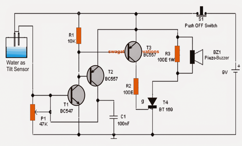
Referring to the simple tilt sensor circuit diagram below, transistor T1 is generally in dormant state and on tilting the water filled sensor assembly, the needles within the sensor container are subjected to a short-circuit caused by water with the availability of positive voltage at T1’s lower part triggering to get activated. T1’s activation triggers those of T2 and T3.
The next transistors stage which T2 provides static bias for T1 making it to be latched with T3 triggering T4 SCR which in turn powers the active piezo-sounder (BZ1). The activation once complete, the circuit can be neutralized using power push-off switch S1.
How to Setup the Circuit
For adjusting the sensitivity of circuit, preset P1 is compulsorily integrated which may be necessary if a different readily available tilt sensor is used.
In the same way, SCR(T4) besides piezo sounder (BZ1)can also be substituted with close comparable parts. Resistor R3 Resistor R3 (100-150 Ohm) is not compulsory.
Circuit Diagram

Another Tilt switch Circuit
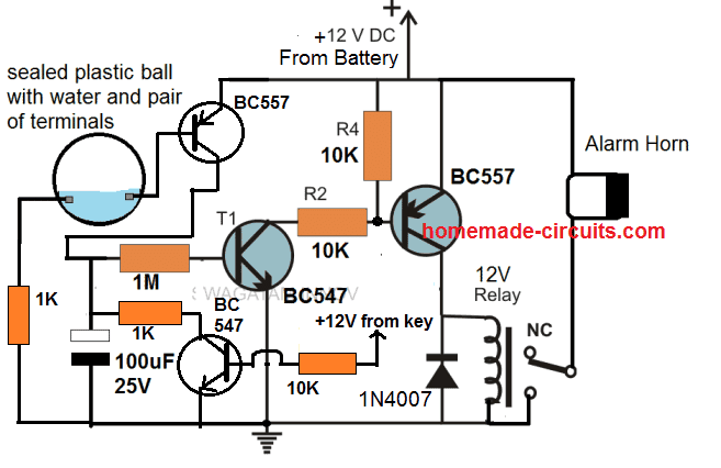
The above design could be much simplified as given below:

Using Tilt Sensor for Protecting a Motorcycle
The two blue transistors along with the 100uF capacitor and the 1M resistor form a simple delay OFF timer circuit.
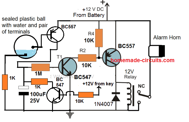
A water based sensor can be seen inside a sealed plastic ball with two metal terminals immersed around the surface of the water. The terminals are positioned in such a way that a slight tilt of the ball removes the water contact from one of the terminals.
When the motorcycle is on stand, the ball remains tilted breaking the water contact between the terminals.
However, if the bike is removed from the stand and attempt is made to start it, the water inside the ball is disturbed allowing an electrical contact between the terminals.
As soon as this happens, the upper BC557 is instantly activated which in turn actuates the blue transistors raising the alarm.
The 100uF capacitor ensures that the alarm does not stop for a few seconds even after the vehicle is restored to its original tilted position.
The lower BC547 is linked with a supply from the ignition key, which means that while the bike is running or active, the entire circuits remains disabled. It is enabled only when the key is removed or unlocked.
For Preventing Car Theft
For preventing car theft, the above design could be modified as shown below:
