In this post I have explained a single phase variable frequency drive circuit or a VFD circuit for controlling AC motor sped without affecting their operational specifications.
What is a VFD
Motors and other similar inductive loads specifically do not "like" operating with frequencies that might be not within their manufacturing specs, and tend to become a lot inefficient if forced to under such abnormal conditions.
For example a motor specified for operating with 60Hz may not be recommended to work with frequencies of 50 Hz or other ranges.
Doing so can produce undesirable results such as heating up of the motor, lower or higher than the required speeds and abnormally high consumption making things very inefficient and lower life degradation of the connected device.
However operating motors under different input frequency conditions often becomes a compulsion and under such situations a VFD or a variable frequency Drive circuit can become very handy.
A VFD is a device which allows the user to control the speed of an AC motor by adjusting the frequency and voltage of the input supply as per the motor specifications.
This also means that a VFD allows us to operate any AC motor through any available grid AC supply regardless of its voltage and frequency specs, by suitably customizing the VFD frequency and voltage as per the motor specifications.
This is normally done using the given control in the form of a variable knob scaled with different frequency calibration.
Making a VFD at home may sound to be a difficult proposition, however a look at the design suggested below shows that after all it's not so difficult to build this very useful device (designed by me).
How it Works
If you do not wish to read the whole explanation, then you can watch this video instead:

OK, so I have designed this simple, basic VFD controller circuit which can be used to control all types of 220V or 120V single phase AC motor, as per the desired specifications. Let's try to understand how the circuit is designed to work.
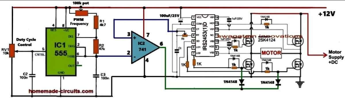
Referring to the above circuit diagram the proposed VFD circuit works in this way: The IC IRS2453 is configured as the basic full bridge or H-bridge inverter circuit which generates square wave output whose frequency is determined by the values of the Rt and Ct components of the circuit.
The output of this inverter is used to control the desired motor, whose speed need to be controlled as per the VFD rules.
In order to convert this square wave inverter into a sine wave VFD circuit, I have configured an adjustable SPWM generator stage using the IC 555 astable and an op-amp comparator.
The IC 555 is wired as a PWM astable circuit to generate the fast triangle waves as the carrier frequency which is fed to the non-inverting input of the comparator op-amp IC 741.
The slow triangle wave, which acts as the reference signal, is extracted from the Rt, Ct junction of the IRS2453 IC and is fed to the inverting pin #2 of the comparator IC 741.
The reference signal is intentionally derived from the Rt, Ct pin of the inverter IC to ensure that the SPWMs are perfectly synchronized with the set frequency of the inverter.
This frequency caan be set by adjusting the Rt resistor which can be a potentiometer.
The 741 IC compares the two input waveforms and generates an equuivaalent SPWM output waveform from its pin#6.
This output is integrated with the low side MOSFET gates of the H-bridge inverter IC so that the square wave operation of the inverter is transformed into an SPWM equivalent sine wave output.
Now, how does this basic sine wave inverter circuit turns into a variable frequency drive?
It is done by providing the adjustments for the frequency control and the RMS voltage control of the inverter output which controls the motor.
So with this sine wave inverter you can adjust the output RMS frequency by adjusting the duty cycle of the SPWM carrier wave and the frequency can be adjusted by adjusting the Rt resistor of the inverter IC which supplies the reference frequency for the SPWM.
How to Calculate Single Phase VFD Parameters
Input Power Calculations:
Power Factor (PF):
This is all about measuring how efficiently we are using AC power. It is extremely important for making sure we size the Variable Frequency Drive (VFD) correctly.
Apparent Power (S):
This represents the total power that’s supplied to the VFD, and it includes both real power and reactive power.
Formula: S = V * I
Real Power (P):
This is the actual power that the motor uses to do its work.
Formula: P = V * I * PF
Reactive Power (Q):
This is the power that bounces back and forth between the source and the load without doing any useful work.
Formula: Q = √(S² - P²)
Output Power Calculations:
Motor Power (Pmotor):
This refers to the mechanical power that comes out of the motor.
Formula: Pmotor = (Torque * Speed) / 9550 (for horsepower).
The constant 9550 is an important number we use in the formula that connects power, torque, and rotational speed when we’re working with the SI system of units.
Formula:
Power (kW) = Torque (Nm) * Speed (rpm) / 9550
What is its Importance
So, what is so important with the constant 9550? It comes from how we convert between different units of power (in kilowatts), torque (in Newton-meters), and rotational speed (in revolutions per minute). This number helps us to tackle the differences in these units, making sure that our equation works correctly.
- Power is measured in watts (W) or kilowatts (kW).
- Torque is measured in Newton-meters (Nm).
- Rotational speed is measured in revolutions per minute (rpm).
To get to that constant 9550, we need to think about a few things:
- Converting power from kW to W.
- Changing rotational speed from rpm to radians per second.
- Using the relationship that says power equals torque times angular velocity (power = torque * angular velocity).
When we do these conversions and simplify everything, we end up with that handy constant 9550 in our formula.
Remember:
This formula is specifically designed for the SI unit system. If you happen to be using different units, for example like horsepower or foot-pounds, then you will need to use a different conversion factor to make it work.
Motor Efficiency (η):
This is a measure of how well the motor converts input power into output power.
Formula: η = Pmotor / Pinput
VFD Sizing:
VFD Power Rating:
The power rating of the VFD needs to be higher than the apparent power of the motor's, so that it can handle any potential overloads without an issue.
Input Current:
We can calculate the input current based on the VFD's power rating and the input voltage specifications.
Output Current:
We also need to figure out the output current based on the power rating of the motor and output voltage.
Motor Speed Control:
Motor Speed (N):
The speed of an induction motor is directly connected to the frequency of the voltage we apply.
Formula: N = (120 * f) / P (where f is frequency and P is the number of poles)
Hi,
I have a bench drill Cthat will not go slower than 450 rpm approximately. I want to drill large diameter stainless steel holes and at that speed the bits burn out. Other than getting special expensive bits I think it may be a reasonable option to use less than 50 Hz input for the 700 watt single phase motor. I am thinking something around 5 to 10 Hz range. Can you advise and are there plans that you can supply for the project.
Cheers.
Hi, I won’t recommend reducing the frequency, instead you can use a back emf based dimmer circuit as explained in the following post:
https://www.homemade-circuits.com/how-to-make-versatile-closed-loop/
Hi
220V AC of main voltage increasing to 310V DC after rectifying by Diode & capacitor
i have question , with 310V how to control 220v motor ?
Hi, the SPWM chopping from the 741 output across low side MOSFET gates will reduce the voltage to 220V or lower.
Hello Sir, how do I control the full H-bridge( with 2110) using Arduino in terms of code and connection?
Hello Everisto, you can use the following Arduino code and integrate it with your 2110 IC for implementing an H-bridge inverter:
https://www.homemade-circuits.com/simple-arduino-sine-wave-inverter/
I wish you did a demonstration of a single-phase project in Multisim using P type and N type Mosfets
Want complete guidence 3 phase vfd circuit diagram pcb ? Parts from where to buy
3 phase VFD circuit is recommended only for the experts, it may not be suitable for newcomers.
how are VFD’s applied to BLDC motors and what are the limits of “overspeed” based on frequency limits?
Thanks
Doug
Hi, Can this very useful circuit be used to drive a syncronous 220-240VAC motor?
I think it can be used to drive the specified motor.
Hi, I have couple of questions…
I would like to control a 1/2 HP single phase pump. The pump uses a permanent capacitor. Could I use a two phase VFD drive eliminating the need for the capacitor?
I would need to know the phase shift that the capacitor introduces.
I would also like to use a solar panel to drive the pump, varying the speed (freq.) and hence power according radiation…. the panel outputs 9.85 Amps @ 45.2 Volts (@ max radiation). I guess I would need a step up transformer to bring the voltage up to 220 V.
Hi, Sorry, I am not an expert with motors, so I am not sure whether a capacitor start motor can be controlled with a 2 phase VFD or not, or whether the capacitor can be removed or not.
If you want to use a solar panel, then certainly you will need to use an inverter to convert the solar panel DC into a 220 AC for the motor
hello, the circuits are tested? I did a simulation of the last schematic and it doesn’t work, included with the optocouplers to drive the mosfets
Hello, you must do the simulation in a step wise manner, first try simulating the 555 section, then the 4017 section.
The 555 and the 4017 sections are perfectly tested OK, but the mosfet section has problems, which might need some corrections. I have added the necessary warning message with the diagram.
can updated circuit with irs2453 be directly used for 250-300 v. or it need to modify as stated in comments using 4N25 optocoupler
If you are using IRS2453 IC with 4 N channel mosfets then you can easily use 300 v directly with the mosfets, no optocouplers will be required.
Hi Swagatam,
thank you very much for this interesting article!
I’d like to build a VFD for a 240V universal motor of about 1 kW; it might peak at 40A during startup and at low speeds/high loads and I was not able to find suitable mosfets, since I’m also concerned that back emf can reach more than 600V.
Do you have any suggestion for suitable mosfets P/N (or mosfets configuration), and do you believe I should use some snubber network or the like?
I’d like very much to hear any suggestion from you, thanks!
Thank you LCU,
For the P channel you can try FQP4P40 mosfets and IRF740 for the N channel. However, there seems to be a mistake in the last diagram.
The source voltage for the P channel mosfets is 310V, and the gate voltage is 12V which cannot work. For switching OFF the P channel effectively, its gate voltage must be same as its source voltage.
Therefore we may have to modify the H bridge section in the last diagram through opto couplers for effective switching of the P channel mosfet as shown in the following example design:
" rel="ugc">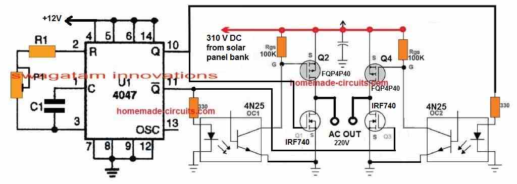
FQP4P40 has a max Vgs of 30V or -30V. When the optocoupler shorts the gate to ground you will have around 0V at the gate and 310V at the source. Would this not make Vgs -310V and destroy the mosfet?
You are right! I think this can be rectified by adding a 15V zener diode across the gate/source pins of the P channel mosfets.
whats the function of bc 557 in the last circuit ? can it or anything else be removed to simplify even more it ?
BC557 allows the IC2 555 to work with a constant current which ensures the PWMs are always consistent regardless of Dc supply variations
Dear Sir,
I wish to make your last drawing…..using 8 mosfet…it is simple from other…So pl give mosfets number…8 nos..
Hello Anilkumar, the upper mosfets can be any 400 V P-channel mosfets, and the low side mosfets can be any 400 V mosfets.
Sir,
I wants single phase 230v 50 hz 2800rpm circuit…is it possible for 2800rpm pump…
Yes that’s possible by adjusting the output frequency to 50 Hz.
Sir,
I will try this method Surely…..
Sure Anil, you can try it.
in the last circuit you changed again to the 4017 ic or is it worng ?
Nothing wrong, it is correct.
is it 10-500hz in 50hz line right ? in 60hz will be 12-600hz ? can’t it go lower like 3-6hz ? what modification it would need for that ?
Frequency can be adjusted by adjusting the R1 pot in the last circuit. It can be any value between 10 and 500 Hz.
and can it be lower than 10 ?
yes it can be lower than 10 Hz
can i reduce this pot to have less range like using 50k or 10k pot wil give what range ?
what pot can give 0-100hz ?
You can try a 100k pot
Hello swagatam
my fridge is 200watts . But because of high surge / starting current the inverter trips. What is the best solution to run the fridge? super capacitor , car battery , change to invreter compressor etc?
Hello JK, The only feasible way is to either to adjust the trip setting to higher level, r to replace the inverter with a higher power inverter. If existing inverter power can be upgraded by adding more number of external batteries then that is also a good option. Super capacitors might not be capable of handling this issue unless many of them are used.
hi sir, i have a problem similar to this project would you help me to answer my question? i want to make a vfd by using igbt instead of mosfet. in all full bridge circuits with mosfets we have both n & p channel mosfets but on internet there are only n-channel igbt s. for making a full bridge with igbt should i use only four n-channel igbt ? ( do igbts have p-channel or they are only in n-channel?).many thanks
Shapur, it depends on the driver IC. If the driver IC is built for driving only n channel deice then p channel cannot be used, and vice versa.
Hello Swagatam,
is this circuit able to run a single phase induction motor capacitor start-capacitor run type?
If not, is there a possibility to make this kind of speed control for this motor type?
Regards.
Hello Bursac, yes according to me the output can be used for operating a capacitor-start type motor, provided the output AC is filtered with some large non-polar capacitors.
I”m a student of University college
I have a project in a single phase variable frequency driver
what is the most accurate circuit diagram here .
The last circuit is the easiest one, but it will need to be built and verified stage-wise and is recommended only for experts who are well versed with electronic circuits, and exactly know how to proceed with the steps, with the help of an oscilloscope.
Also, please note that the various stages involved in the diagram are tested individually for other applications, but the whole unit as one has not been tested yet by me.
Your circuit are very interesting.
I would like to vary the speed of 1.5 HP induction motor.
Is it possible to have a complete circuit diagram including all the components value.
Thank you, I have updated the parts in the last diagram clearly. All the resistors are 1/4 watt, and all the non-polar capacitors are ceramic type.
MOSFETs will be as per the input voltage rating
Hello Sir,
Is this possible to start single phase induction motor without start capacitor using above circuit?
Regards
Manoj
Hello Manoj, I don’t think that’s possible with any circuit
i need full circuit diagram of Single Phase Variable Frequency Drive VFD Circuit
thanks
I am Dip. Elec. Engr.
I want to run variable frequency device for my sewing machine.
I want to use IGBT
which circuit I should use?
You can use the last circuit!
Hii sir..
Can I use this circuit for 1.5hp single phase motor…which is required to run in 10rpm..
For long duration..
And plz explain me how inverter circuit is formed in the above circuit
Thanks sir…im waiting for Ur reply
Hi Chetan, yes you can try it, but make sure you do it only once you have perfectly understood the working of all the stages of the circuit.
Please read the circuit operation for all the details.
Dear Sirs,
I have to control a pump driven by an induction asincron motor, single phase 220V AC, 200w. The motor is sealed and the only „connection” to it is the 3-wire cable: line, null and earth.
The VFD has to run between 20 Hz (say LF) and 50Hz (say HF). The time to increase from LF to HF is variable depending the application (up to minutes). Also the value of LF may be variable. The VFD control (time to increase the frequency)will be made by an Arduino Nano.
Another aspect is the size of VFD. The room is restricted and may depend on application, basically, the body has to be slim and long. So I have to design my own PCB to cope with the room available in each project.
Which might be the circumstances to have a wiring diagram for a VFD 220V single phase input-output, 200w (1/4 HP)?
Thank you.
Hello sir,
I have a my sweety vfd running my CNC Router spindle and it ran fine for months then all of the sudden errored out with a drive circuit error. I can get it to power up and run but the spindle longer turns on. Any ideas?
Hello Jason, most probably it could be due to damaged MOSFETs which are directly responsible for controlling the motor…
Hellow
I am curious and it did not say in the article that I saw. Is it 110 in and what out? Or is it 220 in? If it is 220 can it be altered? I hope so I live in a trailer park and 220 is forbidden by management. But I have a big 110 breaker just setting their unused waiting for me to run it to the shed/machine shop So I can fire up my old professional machines with the help of your VFD I hope. I have had a great deal of practice making my own circuit boards this one seems a lot bigger then what I am used to but I will not be a problem. I have a nice little CNC board etcher that I made sitting in my bedroom.
Hi, the concept can be used with 220V and 110V as well. However the design is indeed complex, especially for anybody who hasn’t built a full bridge inverter yet. I would rather recommend building the second circuit from the following link, and test it on a motor. If you succeed then you can alter the input side and replace it with the VFD control from the above article:
https://www.homemade-circuits.com/5kva-transformerless-inverter-circuit/
hello sir , i want make single phase vfd for a fan(i e. 230 v 5 A, 60-90 W) . I want generate PWM signals by ARDINO. So can you suggest me the simulation ckt & the hardware circuit . Please send me the information regarding that.
Hi Shiva, you can try this:
https://www.homemade-circuits.com/arduino-pwm-signal-generator/
Hello Sir .
How are you ?
Your VFD circuit is correct ?
It is because sometimes on internet some person adds incorrect circuits . Kindly give me a true Answer … I am very thanksfull to you .
Thank you Muhammad,
the concept is correct, but please build it only if you have understood everything correctly and have the required level of expertise, otherwise you may not succeed with this complex project.
Hi Swagatam ,
can you give me a simulation for the scheme,
I’ve tried proteus, but I can’t find ir2110 on my proteus. please help me sir
I have a project to control a single phase motor (VFD)
Please help … rakirebels@gmail.com
Thanks & regard
Sorry Raki, I can’t because normally I don’t depend on software simulation results, instead I believe in mind simulation and practical testing.
Thanks ..
I want to use your scheme for controlling a single phase motor.
1500 watt single phase motor
I have to use half bridge or full bridge ?
thanks & regard
You will need a full bridge circuit, a half bridge is mistakenly shown…..it is not recommended for any motor.
saya membaca artikel anda tentang ” Arduino SPWM Generator Circuit – Code Details and Diagram ” (// By Swagatam (my first Arduino Code)
bisakah code itu dimodifikasi ? saya membutuhkan pengendalian frekuensi untuk mengatur kecepatan motor satu fasa. saya menggunakan IC ir2110 sebagai driver
Thanks & regard
Yes it can be modified but it cannot be varied using a pot.
The total time of the two sets of codes is 20 ms, so each set is 10 ms long…you can adjust the microsecond values to increase or decrease the 10 ms value to any other desired value proportionately.
hello Mr. Swag,
I assembled a half-wave inverter. I experienced failure. i want to ask, what is the output voltage on pin 2 and 7 ic 4017? , what is the output voltage on the pin HO, LO,VB and VS ic ir2100. at no load condition .. thanks Mr.Swag
Hello Raki, you must build and verify the different stages separately, and then integrate them together. The voltages will not reveal anything because the outputs are sequencing at a high frequency. You will need a frequency meter and an oscilloscope to test the various points, and before that you will have to understand how all the stages and the ICs are designed to work, their specifications etc.
This project is not for the newcomers.
hello sir .
may i know your email
thanks & regard
Hello Raki,
please see the “contact” link at the top of the page.
hello sir,
in a half-wave circuit
Is the negative voltage on the motor connected only to the motor?
or also connected to ground (pin # source on LO mosfet)
best regards
Hello Raki,
All the ground symbols are common and should be connected with the each other.
Hello Sir …
in my halfbridge circuit
lf pin3 ic2 is not connected to the gate, the voltage at the source is measured 180V, and the lamp is on
but if pin3 ic2 is connected to the gate, the voltage at the source is measured 4V, and the lamp is off.
if all components are installed according to your design and soldered correctly. what else should i do?
please give me your advice
thank & regard
Hello Raki, If you assemble everything together then it may show many problems. So you will have to build and confirm the various stages separately, and then join them step by step.
First build the IC1 and IC 2 stages and check the pin 3 of IC2 for a varying PWM in response to a varying external voltage at pin 5 of IC2.
After this build IC 4017 stage and connect IC1 output with it and confirm the output of IC 4017.
After this build the half bridge, and connect it with IC 4017 and check how a load responds to this.
If everything work perfectly then finally connect the pin3 of IC2 wit the MOSFeTs.
Swag,
I would like to use your design for a lathe in my wood shop. My question is will this work for my application?
The motor is 3/4 hp, 115V, 1PH, 60 Hz, 1720 RPM (no load), 6.7 FLA.
Please let me know. Thank you.
Hi Paul, it will surely work for the specified motor. I would recommend the last circuit since it’s a full bridge circuit and will provide full control of the motor speed.
Thank you very much! I am anxious to give this a try and I’m sure I will be asking a few more questions before I am all done.
Thank you, wish you all the best!
What is the purpose of decade counter 4017 in this circuit?
It is for driving the IR2110 IC inputs
Hello Swagatam,
Very nice post. I was wondering if I can use this circuit to control the speed of an single phase capacitor run induction motor. For example one like those small fan motor of the evaporating unit of an Air conditioning
Many thanks
Thank you Steve, yes it can be definitely used. But I am wondering why can’t an ordinary light dimmer switch be used for the same purpose?
Hi Mr Swag i redesigned my H bridge driver and if i test it with motor ,my ic driver just brew up and the only pin that may course this problem is pin 5 since it connected to high voltage and there is no diode or resistor across it ,is it correct like this? im scared to put another one if it blow again i will be in short of them
Hi Ayanda, As you will understand that the H-bridge design is a standard design taken from the datasheet of the IC, so it has to be correct in every manner, pin#5 of the IR2110 is correctly configured, since it is as per the diagram in the datasheet.
Configuring an H-bridge using driver IC is always a little problematic unless it si done on a well designed PCB, and make sure to add 1k resistors across gate/drain of each mosfets, this might help to safeguard, but you can be never sure unless you have the most correctly designed PCB layout for the H-bridge.
If you want to avoid a driver IC, you can probably opt for the following H-bridge concept:
https://www.homemade-circuits.com/arduino-full-bridge-h-bridge-sinewave-inverter-circuit/
you can connect the NAND inputs to the IC 4017 outputs
thanks bro i will do that ,maybe there is a little infomation that i have missed but protecting it would help me
Wish you all the best bro!
Dear MR Swag,
i want to make this circuit of VFD but using arduino as the designed one in https://www.homemade-circuits.com/arduino-full-bridge-h-bridge-sinewave-inverter-circuit/
but i need to vary the frequency using the arduino itself.will be any need for the 555 timers and ic 4017 ?? and will be the arduino Uno effective in changing the frequency ?
Mohammad,
It may be possible to replace IC1, IC2 and the 4017 with an Arduino, but designing the program can be complex. However if you only want the frequency adjustment to be implemented from the Arduino, in that case you can replace IC section with any Arduino frequency generator stage
Thanks for the reply mr swag,
what i really need is to control motor speed using arduino and the power source for the circuit is from AC 220 volt which is available in any home not a DC batteries as implemented in https://www.homemade-circuits.com/arduino-full-bridge-h-bridge-sinewave-inverter-circuit/
Mohammad, for this you will have to have an adjustable PWM output from the same Arduino board, this pwm could be configured with the low side mosfet gates for implementing the required motor control action
thanks Mr Swag for your reply,
thank god , i found a code for varying the frequency using arduino but now i want to change speed for 240 v AC induction motor and the output of the arduino is 5 volt.
will the use of nand concept of ic4093 useful with arduino which now vary the frequency or not ?? and how can i reach to 240 v of the ac motor Will the transformer concept 12-240 will be useful and will be the output frequency from the transformer variable or fixed ??
Muhammad, please specify the pinouts and the configuration of your pwm control output. I may try to solve it
I just now remembered that the pwm control can be implemented through an arrangement that may allow the SPWM width control for this design:
https://www.homemade-circuits.com/arduino-full-bridge-h-bridge-sinewave-inverter-circuit/
Dear Mr Swag,
thank you so much for your support;
i just need two pins from arduino as 9 and 10 for pwm as you mentioned in
https://www.homemade-circuits.com/arduino-full-bridge-h-bridge-sinewave-inverter-circuit/
so that the arduino can change the frequency from 0 to 50 to control motor speed.
the AC induction motor specification 250W 1.5A 240 V. by varying the output frequency of the motor from 0 to 50 hz the speed of the motor will change but i do not want to use a battery as a power source for the circuit i just need to get its power from home ac electricity(220 V).the speed control of the motor will be by arduino. will the nand concept mentioned in
https://www.homemade-circuits.com/arduino-full-bridge-h-bridge-sinewave-inverter-circuit/ be helpful for my case?
Mohammad, I was asking about your Arduino circuit which you found from another source. I wanted to know about it, since you said you found the PWM control codes.
OK, I understood, you are referring to my recommendation, regarding varying of 8 and 9 pin PWM widths…let me think about it.
Dear Mr Swag
the source for varying the frequency in single phase motor
https://github.com/Terbytes/Arduino-Atmel-sPWM
https://www.youtube.com/watch?v=3DjKxDL_Qc0&t=925s
OK, but this will need to be included in the Arduino system which is explained in the full bridge Arduino article??
ok mr swag but my question is will be the output frequency of transformer fixed or variable and i read that the current will step down in the case of using transformer and i don’t want to use a battery how can i achieve this using AC as the power source for the circuit ??
frequency would be fixed because we won’t be using V/Hz principle, we would be using a PWM control based principle. You can use AC by feeding rectified DC 220V to the mosfet supply lines.
Thanks sir for your response.but if i connect pin 3 of ic1 automatically to ct of IRS what will be the benfit of ic2 ?? and i could not find IRS2453 in my city are there other replacements ?? and what about the previous circuit which uses IR2110 is it synchronized with the SPWM from the IC 555 or has the same issue ?
Hi Mohammad, IC2 is for generating the SPWM, IC1 is for generating sample triangle waves for IC2, all are interdependent with each other.
You can Google “full bridge driver IC”, or half bridge driver IC, and see which one is available in your area.
The previous one is synchronized through IC 4017.
hi sir,
if i have AC 220 V 1/4 hp compressor of household refrigerator and i want control its speed what is configuration suitable for Rt/Ct associated with the IRS2453 and R1 associated with IC1 ??
Hi Muhammad, the full bridge stage is actually not synchronized with the SPWM from the IC 555, therefore the output may not be correctly optimized AC. Therefore I would suggest to eliminate Rt/Ct, and feed the Ct pin of the IC with frequency from pin#3 of IC1.
IC1 frequency may be set at the desired output frequency by measuring the output of IRS IC with a frequency meter and simultaneously setting the R1 220K preset…this will allow the full bridge stage to be synchronized with the SPWM control frequency and also allow to get the required 50Hz frequency at the output
Thanks bro,one more question ,why is it necessary for Drain pin in HO side is connected to power while the other one is connected to load. will this not affect the mosfet ?,just asking i did read about the mosfet from the page you shared yesterday.
Ayanda, actually you have asked a very important, I am sorry I think the half bridge configuration which was taken from the datasheet itself is not correctly connected. The connection should be in the following manner, I’ll correct all the diagrams soon
" rel="nofollow ugc">
Thank you very much Swag we appreciate your help bro.i have learnt a lot now and i’m hoping to get this done before the second of may which is two weeks from now and i will be presenting my project but i’m still working on it.
You are most welcome Ayanda, I have done the necessary correction in the design, you may check it out now.
Hey swag .
Plzz give me a motor rating …??my project is 1 phase vfd for 0.5hp induction motor can I used your circuit in my project ..??? Plzz help me broo
Hi Satyajeet, the motor rating will depend on the mosfet rating and the applied voltage to the drains of the mosfets, or vice versa, meaning the mosfet and the supply voltage could be selected as per the motor specifications.
Hi Mr. swagatam.
can u help me with single phase VFD run with arduino . MATLAB/SIMULINK code has been done to drive the bipolar full bridge PWM signal to MOSFET with variable frequency and modulation and will upload to the arduino.
So, my problem is how to make circuit for gate drive the MOSFET to drive the 240V 70W ceiling fan.? can u give me any suggestion. Thanks..
Hi ISZ, An exactly similar question was asked many days ago by one of the readers and I had provided him and appropriate diagram for implementing the same, now it may be very difficult for me to search that particular comment.
Anyway if you are trying to feed the bipolar pulses into a n-channel based full bridge mosfet configuration then you might require a bootstrapping mechanism for the high side mosfets, right? Without this you won’t be able to drive the high side mosfets, so have you taken care of this??
hello sir ,i made a simulation for this circuit in multisim program but it doesn’t work for me.i can send you a photo from the simulated circuit if you wish sir :).
Hello Mohammad, Simulators can produce wrong and misleading results, how can you confirm it is giving you the right results? If you build this circuit step wise with proper understanding the circuit will surely work…
Ok,thank you so much sir.I will do my best with god permission.
Hello Mr. Swagatam, could you explain why the output (pin3) of the second 555 is connected to the HO and HI outputs with inversely polarized diodes? regards
Hello Mr. Benjamin, that is not correct, and I have mentioned about this and have presented the finalized design at the end of the post….the diode links must be connected with the mosfet gates.
Hello Mr. Swagatam, would you be so kind as to send me the image of the last scheme that has the corrections to my email? Since when downloading the image you can not see the values of the components well. Greetings Benjamin
Hello Benjamin, I’ll try to update the diagram in the article soon with larger component numbers.
Okay,thank you.
Thanks man
Welcome dear!!
Hello again .
With all due respect brother I have one more question .
1. Why 2nd 555’s I mean ic2 output is directly going to mosfet’s gate ?
Please clearify this what’s purpose of it . If we remove ic2 from circuit it’s still working .
Hi, If you are not including R8 pot and not integrating the IC2 output with the mosfet gates, then you won’t be able to control the speed of the motor, the option will be simply lost.
IC2 helps to transform or chop the mosfet gate drive into an SPWM format, and R8 allows the PWM control of this SPWM, meaning by rotating R8 you can reduce or increase the SPWM duty cycle or the width of the pulses. narrow width will cause decrease in motor speed, wider pulses will allow higher speeds.
hello sir,
we have completed this project and i have a few questions please answer these questions it will be a great help 1.why we are using 2 555 ic’s ?
2. why we using pin 2 and 7 of 4017 ?
3. we have used ct also for protection i will share the pictures .
Hello Farhan,
The two IC 555 are used for creating SPWMs in response to the 100Hz sinewave ripple sample achieved from the bridge at pin#5 of IC2
The actual sequencing of IC 4017 is from pin#3 > 2 > 4 > 7…by skipping pin#3 and pin#4, we are trying to insert a good “dead time” for the mosfets, although this can also result in significant amount of voltage drop at the output.
Also, the use of a half bridge at the output could result in further drop in voltage.
so the above things must be considered….
the half-bridge could be replaced with a full-bridge driver circuit for ensuring the correct level of output for the motor.
sure, the images will be greatly welcomed here,,,keep up the good work.
We have hooked up the vfd in stages and began testing with and oscilloscope. We are getting a square wave coming out of pin three of ic2 and 1c1. We also looked through the previous comments and removed the 557 and other components as you stated. What should we be looking for on the oscilloscope going to the 4017 and further more on the ir2110?
isolate the IC1/IC2 entirely and test it separately, connect the upper arm of the R8 pot at pin#5 of IC2 with the positive line.
varying this pot should create a variable PWM at pin#3 of IC2. The frequency of this PWM can be varied by adjusting R1.
Once this is confirmed, connect the R8 upper arm with 100Hz from the bridge, and check whether pin#3 of the IC 2 is producing an SPWM or not, it should.
Once this is confirmed you can integrate the IC4017 with this stage and verify the alternating pulses across pin#2 and pin#7.
similarly confirm the motor half bridge driver separately and finally integrate it with the IC 4017 output
I have hooked up the whole circuit and i am able to vary my current. The problem is i am feeding the top mosfet with 170 v dc to run a 120vac motor but I’m only seeing about 4vac across where the motor would go. Any thoughts on the possible issue?
Hooking up the whole circuit is not the right way to go, you must build it stages-wise and confirm the stages separately, once confirmed then you can integrate them together for the finals results….as you can see there are many stages in the design, unless you are sure each one of them are doing their job correctly you cannot be sure of the output performance.
please check the mosfet gates with an oscilloscope, check what waveform you get here? If it’s an SPWM then it is fine otherwise you may have to go right back and begin investigating from the IC1, Ic2 stages.
Okay, to Know, in what frecuency ranges can you works
you can set the frequency by adjusting R1 to the correct range, this can be set using a frequency meter.
Thanks for answering Mr. Swagatam. Excuse me I thought the circuit was for that purpose (vary the speed). But could I use it for that purpose or not?
Benjamin, you should only use the voltage control pot for varying speed, not the frequency pot
Hello Mr. Swagatam, first I wanted to thank you for all your contributions to fans like me.
I have a doubt about the circuit, by reducing the frequency of the motor this consumes more current, how do you solve that problem. As far as I know, the voltage applied to the motor must be reduced, but I do not see that system in the circuit. Greetings Ben.
Thank you Benjamin,
The frequency adjustment here is not for controlling speed, it is for ensuring that the motor operates with the correct frequency as specified by its manufacturer. It is specifically used when a 60Hz motor is being used with a 50 Hz source and vice versa, and then the pot may be used for correcting the frequency as per the spces.
the voltage output can be varied by adjusting the pot at pin#5 of IC2
Good morning sir. Pls, after putting up the circuit, I realised that there was no signal entering into pot 14 of IC4017. Sir, pls, wat do u think could be the problem? Thanks in anticipation as I await your response.
Good morning stephen,
if you put up the whole circuit together, it is never going to work for sure, and that’s true for most of the circuits which have different stages.
you should build and confirm them stagewise, and this will require some serious understanding regarding the various stages.
anyway, by pot 14 you mean to say pin#14?
from where is pin#14 getting its signal? it is from pin#3 of IC1 right?, so check whether your IC1 is oscillating or not…keep verifying all the stages in the same manner.
by the way the following parts can be removed from the last diagram
T2, R9, R10, C7, C6, and connect pin#16 of IC 4017 directly to the positive line
I have done what u told me to do but what I realized is that it is only the pin Ho dat has voltage on it while the pin Lo does not and variation of the two potentiometer does not have effect on the Ho and Lo voltage. Sir, what else do u think I can do.
did you check whether IC1 was generating the oscillations or not…. in response to these osculations at pin#14 of the IC4017 it is supposed to generate alternating ON/OFF voltage across its pin2 and pin#7, isolate the respective stages and first confirm them separately….checking HIN and LIN can be done later on…
IC2 pin#3 should be generating varying PWM in response to a varying voltage at its pin#5, this is the next possible thing that you must confirm
Thank u sir, will give it a trial and get back to you.
you are welcome?
when the R8 potentiometer is adjusted, what is the variable parameter here? its variable the voltage or variable the ripple frequency 100Hz to pin 5?
the variable parameter is the voltage of the ripple input, or the amplitude of the applied ripples…
Good day sir. Pls, I don’t know if you can help me with a mathematical analysis of how you arrived at the values of each of those components used in the circuit. Thanks in anticipation.
Stephen, sorry, that will be a lot of explanation, won’t be possible at this moment.
Will a 1HP, 230V motor work with this circuit? Please reply ASAP cuz i am making this as my project and need to submit it within a couple of days. Thank you.
motor power rating can be matched by suitably upgrading the mofet rating, so any desired motor rating can be used…
however make sure you have understood the circuit and stages perfectly before you try it.
the circuit will need to be built stage-wise, by confirming and testing each one step-wise, and then integrate them for the final outcome
So if I use a 230V motor, I will have to give the ‘motor voltage’ as 230V too?
actually It should be 330V DC for a 220V motor
If we supply it with 330V DC, won’t it affect the circuit? Cuz the voltage will get supplied to other parts of the circuit too right?
330V DC must go only to the mosfet drain, not to any other section of the circuit.
We are getting a DC output across where we are supposed to connect the motor for output….around 200mV, we haven’t given any motor voltage yet….So basically without motor voltage and motor….we are getting a 200mV DC output…is it working that means? And also….we are using a bred board so how are we supposed to make the ground connection to 0?
sorry, that’s not the right way to check…you must verify the various stages separately.
using an oscilloscope first confirm whether the IC 555 stage is delivering the PWMs or not ( by varying the respective presets)
then verify whether the IC 4017 is responding accordingly or not, and then finally verify the output from the half-bridge and check if it is producing the PWM based chopped square cycles across its output pins…all these will need to be done via an oscilloscope.
ground connection refers to the negative line from the power supply, all the negative lines must be connected in common, including the motor supply’s negative line.
Thanks, Mr.Swagatam.
this single phase VFD is controlled by R8 pot. So, I’m planning to replace the 555 timers with a microcontroller. If I use (https://www.homemade-circuits.com/2017/04/arduino-spwm-generator-circuit.html) method, is it going to work?
Daniel, yes that may be possible, however R8 is also synchronized with the mains cycles, so your Arduino will also need to be configured to do this…
If I didn’t use 240v/12v transformer (but use direct supply with 12V adapter), how I can variable for voltage adjustment at potentiometer R8 ?
transformer is required for this project, smps supply will not work
this circuit is tested? where the triangular & sine wave come from?
It is tested, the triangle waves comes from the 555 IC, the sine comes from the mains transformer secondary.
thanks. how about the motor voltage ? 310vdc ?
you can apply the 310V separately to the point labelled “motor voltage”
Hi sir, many thanks to you for doing a great job. Pls, what is the importance of the capacitor with rating 1uf/1kv in the circuit?
Thanks Stephen, it is positioned to control high voltage spikes across the lines.
Appreciate sir. Pls, why is terminal 5 of IC IR2110 connected to the source of the Ho mosfet? Won’t the motor voltage destroy the IC IR2110?
Stephen, it is to enable the bootstrapping process, otherwise the high side mosfet will not conduct.
Thank you sir, appreciate.
My pleasure!!
sir… what kind of diode “2V7” that are use in the circuit?
It is a simple zener diode, you can replace it with a 3V zener, or a 3,3V zener
hi again sir,
what the value capacitor of C11? 10uF/1kv or 20mF/450v ?
Hi ai,
the uF can be as high as possible, and the voltage value should be at least 100V higher than the motor peak voltage supply level.
hi dear swagatam
I have a question about drive half bridge circuit IR2110
in half bridge source pin upper conected to drain pin The bottom ؟
Thank you
Hi Reza, the lower line or the source line is connected with the common negative of the supplies…..
hi sir, good day.
Im not familiar with the 555 timer ic and 4017 ic. can you explain more details about how its works for both type of ic in this circuit. can we control LN & HN at IR2110 ic with microcontroller ?
Hi Bryan, it can be a long explanation, not possible to do it here.
Basically 555 IC2 is configured as a PWM controller, for this it requires a clock at its pin#2 and a modulating voltage at its pin#5…when this is implemented a correspondingly varying PWM is obtained at its pin#3
an elaborate explanation is given here.
for the IC 4017 explanation you can read this article:
https://www.homemade-circuits.com/2011/12/how-to-understand-ic-4017-pin-outs.html
hi,
can i change the K2837 mosfet with another type? from your opinion, what type/brand of other mosfet that can be use because i cant find this type of mosfet in my county.
thanks….
Hi, the voltage and current rating of the mosfet should be a little higher than the load’s V/I rating, as long as this is satisfied any equivalent type of mosfet can be used. you can confirm it through the datasheet of the selected device
hi,
can i use this circuit to control my ceiling fan? where the adjustable PWM located? i want to replace it with microcontroller…
Hi, R8 is the speed control knob, however for fan a BLDC motor circuit will work better.
https://www.homemade-circuits.com/2017/07/bldc-ceiling-fan-circuit-for-power.html
thanks for reply. but im want to control an AC ceiling fan. can this circuit perform it?
It can be used for controlling any AC motor including a fan, but fan can be controlled using a simple dimmer switch
Hi Mr. Swagatam,
I wonder how do we know if we have the correct v/f ratio since it doesn’t automatically change the frequency or voltage when we turn the potentiometer. And what will happen if we don’t get the correct ratio.
If i put resistor parallel to R1 and R8 is it possible to make it auto adjusment for v/f? I mean i put fixed resistor for R1 and R8 in a v/f ratio and put another potentiometer in parallel to those so i only need to adjust 1 potentiometer to get the speed.
Hi Ari, The correct V/F ratio can be obtained from the motor specifications, and in the circuit these two parameters can be fine tuned using the R1 and R8 pots.
auto adjustment is actually not required because the supply from the grid will be relatively constant and will not disturb the settings.
if you don;t get the correct ratio your motor will not be able to run at the optimal range, however accuracy is not critical here…
Hi Mr. Swagatam.
Thanks for you reply.
I mean how do we tune the R1 and R8. If we turn R1 to get a speed then i should adjust the R8 too to get correct V/F ratio. How do we know we adjust it to correct ratio. My motor is 220V 50hz, it means ratio is 4.4. So do we just measure the resistor R1 then adjust R8 accordingly to ratio?
Thank you.
Hi Ari, R1 can be used for adjusting the frequency, for example say from 50Hz to 60Hz etc.
R8 can be used for changing the voltage level, R8 will basically change the PWM which will in turn help to change the output voltage. changing R1 will impact the waveform slightly as it will alter the number of “pillars” on each output wave when viewed in the PWM mode, but this will not affect the load
…you just have to measure the output frequency and voltage and make sure it matches the motor’s technically specs….calculating ratio is not required
Thank you for your information Mr. Swagatam.
God bless you.
you are welcome Ari…
I’m sorry. One more question.
Will it reduce the torque when i reduce the speed?
torque is directly proportional to speed, so yes torque will be reduced at lower speeds.
Hi Mr Swagatam, i’m sorry i’m back with a question since i had a doubt.
The input 12V power supply, it should the same watt with my motor watt that i use, right?
Hi Ari, the 12V is meant only for the circuit, and for modulating the IC2, it has no relation with the motor specifications, the motor supply is supposed to be separate and applied at the mosfet drain, indicated as “motor voltage”
the 12V could be rated at 100mA or 500mA….
Oh. Ok. So if i read from others whom ask here. I just need to rectified ac to dc and maybe put up a capacitor for flat the ripple and no need complex circuit for it. Isn’t that right?
yes that’s correct, but remember the modulation feed must come from the unfiltered point of the network as shown in the diagram
So i feed rectified ac directly to pin 5 ic2? Should i reduce it to 12V first before get into pin 5 ic2? As i know ic555 maximum voltage is 15V.
yes feed the 12V 100Hz rectified AC at pin#5…. if the trafo is 12V rated then no need to reduce it
…to be on the safer side simply use a 0-9V trafo instead of 12V
I planned to use smps power supply to feed the 12V actually. And make different circuit for mosfet.
SMPS will not give you the AC ripple sample for the pin#5 assessment.
dear brother i want to ask how we are varying voltage and one more thing. is mosfet acting as an inverter ?
Dear Anshdeep, the voltage is varied by adjusting R8, mosfets are acting as half-bridge motor driver.
i want to ask if you connect the circuit and get a result
hi iwant to ask if you get agood result
hey!
I have got a problem. Circuit is not working for me. I am using single phase AC motor 0.35A 230V. I also measured signal on load – nothing else except around 12V peak to peak distortion. I used the same parts as you. For motor supply I used rectified mains voltage: 310 V DC. Also with oscilloscope I noticed, that PWM signal going out of 4017 and also driver is okay.
It seems your driver IC has problems and is not responding to the processed signals from the IC 4017, please check whether the 4017 output is feeding the signals to the driver IC LIN/HIN inputs or not, and check whether the driver IC output is feeding the signals to the mosfet gates….you can confirm these by temporarily disconnecting the PWM diodes across the gates of the fets.
initially use a 220V filament bulb for testing the response
Hi swagtan . well i really like your articles on this tech stuff. well i did make the circuit and i have no oscilloscope or fancy lab test equipment but then i managed to hook a incandescent bulb to test it first. There was a bit of success on the dimming effect or something like blinking cause of the lower frq. but then.. i actually used a mosfet that is 500v and 20A but and all i did is to do away with the ir2110 and i drove the mosfet directly. The bad news is that when i hooked a 750watt induction motor to test, there was the magic smoke from the first 555 timer and then i also noticed that the mosfet to was gone… damn i couldnt tell wat exactly went wrong since from my math the 20 A FET was good to handle the motor!
Hi Paul, Thanks for updating your experience with the design, although I am not exactly sure of the problem you faced, nevertheless the last design certainly needs a correction, I'll update a few improved designs soon in the above article which according to me will make more sense technically. kindly bear with me.
…I have updated the corrected version at the end of the post, you may check it out and analyze the same..
Thanks for your quick reply.
As I know, when intensity of sunlight increases, the voltage output from the solar panel will also be high, to maintain speed of the motor, VFD will adjust Voltage/Frequency ratio. And these job will be done by VFD automatically. (Correct me if I am wrong)
But, from your circuit diagram, it looks like, there no option to change the frequency. It is fixed to a single value by placing a capacitor.
OK got it, what you are suggesting could be a solar VFD, or a VFD enhanced with MPPT for working with solar panels.
The above circuits are not featured to do this automatically however an MPPT feature could be integrated with the above design by including an opamp follower stage with pin#5 of IC2 as shown in this MPPT circuit:
https://www.homemade-circuits.com/2015/11/simple-solar-mppt-circuit-part-2.html
Thanks a lot
That means i have to cascade these 2 circuits i.e. the 1st one is above circuit and at the pin no.5 of IC2 of above circuit, i have to connect the 2nd (simple solar MPPT circuit).
Or something else?
Thanks & Regards,
Nitin A Kallole
yes that's right, if possible I may post the idea soon in my blog.
First of all Thank U Very Much Sir…
I have some doubts regarding above circuit.
1. Can we use same circuit for solar powered pumps. In solar powered pumps/motors that draws water from bore well, the job of VFD is to control speed & torque of the motor.
2. If yes, does it use MPPT (maximum power point tracking) algorithm.
3. As intensity of sunlight is not same throughout a day, the job of mppt draw maximum power. So that, these VFD's will work in cloudy climate also.
Thanks & Regards,
Nitin a Kallole
Thanks Nitin,
yes you can use it for varying the speed of the motor.
A VFD is not related to MPPT according to me, so MPPT is not relevant with this device.
Said that, you can surely employ an MPPT externally for ensuring maximum efficiency from the solar panel.
respected sir,
i have single phase induction motor which has spec. 1hp,7 amp.,50-60hz frequency, 1440 r.p.m
this motor i used in power press machine now i required to control the speed of motor, i had been used dimmer switch which was rated 3000watt but motor run on full load dimmer was failed so now i required to control motor speed from frequency control method so which kind of replacement is need in this circuit. when motor run on full load that time amp goes to 8 to 10.5 so which component is need to control this high amp. also i can not effort readymade vfd drive.
hope you will help me as possible as soon
regards,
kishan s ghetia
Hi Kishen,
A VFD may not be suitable for your application, you will need either a dimmer which you have already tried, may be due to low power triac your dimmer got burnt, I think you can try a dimmer with a 40 amp triac such as a BTA41/600, and mount it over a big heatsink.
you can also try a PWM version for the same.
I have explained the circuits in the following article which you can probably try.
But these are relatively complex circuit and only experts are advised to work with the.
https://www.homemade-circuits.com/2012/12/high-current-triac-bta41600b-datasheet.html
dear, sir
i have SINGLE PHASE INDUCTION MOTOR 1HP, 7AMP, 50-60Hz frequency , and r.p.m is 1440 which is use in power press machine .
now i want to control speed of motor by using this circuit so which kind of modification will required. when motor run on full load it's amp was 7-10 so what kind of component is replaced in this circuit. please give me the list of component
in past i had been used dimmer switch which is rated 3000watt but it had been failed in full load of motor so i want to control by frequency method.
Hello sir, my team has purchased all the components for this project. We have also assembled the circuit on breadboard. Now, we have some doubts. Please help us out with them.
1. In the diagram drawn by Mr. Vuleek Unteeluv, it is said that we have to connect "motor voltage" at the drain pin of "HO MOSFET". I assume it to be the single phase voltage. If I connect the phase wire at the drain pin of "HO MOSFET" then where should I connect the neutral terminal? Should I connect it at the source pin of "LO MOSFET"? If I do so, I fear that the negative of DC voltage (Ground symbol of diagram) and neutral of AC will get shorted.
2. Is it compulsory to give rectified 12VAC or can I connect 12V battery.
Please help sir. It's urgent. Thank you very much for your support.
Hello Akbar,
NOT the phase, you'll first need to rectify the mains 220V AC into DC (330V)using a bridge rectifier, and then connect the positive with the mosfet drain, and the negative with the source….
the 12V can be any form of DC…the word "rectified" refers to the conversion of a 12V AC to DC that's all nothing critical about it.
Thank you so much sir for your quick reply. I understood the circuit now. Just for verification I am mentioning what we will do:
We will connect 12V battery for 12V DC power
We will rectify AC (by using our own external bridge rectifier) to 330V DC and then give positive to MOSFET (HO OUT) Drain and negative to MOSFET (LO OUT) source.
So this basically means we need to design our own simple 330V rectifier. After reading other comments I believe that this rectified voltage must not be pure DC but should have some ripples in it to act as sampling.
Am I correct Sir?
Also, second doubt I have is:
Ground of 330V DC and 12V DC will then be same if I connect negative of 330V DC to source of LO OUT MOSFET. Will it be safe? I mean, it will not cause any circulating current?
Thank you again for your quick reply to my previous doubts. Do reply soon.
You are welcome Abrar!
the 310V DC can be a pure DC, it need not be with ripples, although ripples might not affect the motor performance.
but pin#5 of IC2 will need a 100Hz sampling…so I think the last diagram has a mistake, it's not as per the second diagram (pin#5 needs to be connected to 100Hz ripple separately)….I'll correct it soon
yes the negatives of the two voltages (310V and 12V) should be connected in common, there's no danger in doing so and is necessary to make the circuit work correctly
Thank you again sir for quick reply.
1. Sir how would I provide 100Hz sampling to pin 5. Is there a separate circuit? If yes, then which circuit?
2. Can you please recommend us a 230VAC to 330VDC rectifier circuit?
Sir do reply soon because we have to build the pcb footprint by tomorrow night.
I know, I don't need to mention again and again to reply soon because you are very fast in helping. Its just that we are in urgency. Sorry for disturbing you.
Thank you Abrara,
A rectifier can be built by using 4 diodes as shown in the diagrams above….I have corrected the last diagram you can check it out
But I wonder if you don't know how to build a rectifier how you would be able to succeed with the above fairly complex circuit?
Hello, can help me with some schematics for a power supply to run my tattoo machines
please provide all the electrical specs of your tattoo machine
i did work little bit on VFD ,but my requirement is to run Air Conditioner Compressor motor of 1 ton . i tested above circuit ,it showed Pure Sine Wave at the output but this Sin wave remains stable just on 50 HZ frequency , on slight variation in potentiometer value ,it shows various noises .My aim is to vary frequency in between 20 to 50 hz with sin wave. The above circuit is feasible for 1 hp and i need to upgrade it to 4.7 hp ,3.5kv and 15 amp let me know sir how could i do that .
I did work little bit on VFD ,but my requirement is to run Air Conditioner Compressor motor of 1 ton . i tested above circuit ,it showed Pure Sine Wave at the output but this Sin wave remains stable just on 50 HZ frequency , on slight variation in potentiometer value ,it shows various noises .My aim is to vary frequency in between 20 to 50 hz with sin wave. The above circuit is feasible for 1 hp and i need to upgrade it to 4.7 hp ,3.5kv and 15 amp let me know sir how could i do that .
You can upgrade the power of the circuit by connecting more number of mosfets in parallel.
50Hz is for 220V…and 60Hz for 120V and so on…so the frequency should be in terms with the voltage level as per the standard specs…..and by the way noise can be filtered by suitable LC filter circuits
I see the question of 'have you built this circuit and tested' was a no. Has "anyone", successfully, made this work? I just finished drawing it in eagle cad. When my dad asked – is this a tried design or just another Internet postling. So, I have to know is there a working board out there?
Im using 200 volt supply, and need frequency range from 0-50 Hz or around it. It can be less than 50Hz but i need low frequency. Which circuit will help me from these three? If not then can you provide me one?
you can try the last circuit shown in the above article.
I really need to use AC main to power my DC motor instead of battery. I have 19amps 27v 2200rpm permanent magnet DC motor which consumes 36v 200ah battery anytime I want to test run it. Help me design an AC input/DC output that will handle 19a 27v DC motor without voltage drop.
The best and the safest way would be to use a 24V 25amp transformer, and rectify its output for the motor…this could be made by anybody safely and with 100% results…any other option could be risky and might require advanced knowledge regarding the concept.
Can I use this circuit to control induction motor 1 phase?
yes you can do it…
I think a simple PWM controller for the field winding would also do the job…….
actually brother My requirement is to run single phase 2hp 220v 50hz 12amp motor using solar power, i am having 800v dc 4800watts solar panel int that i want to use mentioed single phase motor and also want home purpose, can i use this circuit as for my req.? What model mosfet iwant to use?
yes brother definitely you can use the circuit, make sure to select the mosfet as per the load specs.
however you must have the assistance of an expert electronic engineer while building the proposed circuit because the circuit could be too complex and not suitable for the newcomers.
Got it brother, the borewell submercible pumb having three wire system 240v single phase, in that case how the circuit is used to run the motor ?
I think one of the wires out of the three could be for "earthing" purpose…while the other two for LIVE and NEUTRAL connections…you will need to find the Live, and the neutral wires and connect these between the mosfets, as shown in the diagram.
Hello 🙂 i'm back.. 1 month has passed since i posted. Couldn't work on the project because school started,had some exams at another course,and i had driving license exam..soo i didn't had much time to spend on the project. I worked on my PCB these days,and there are good news and bad news. The bad news are that i missed something,and some components heated up. I solved the problem but my circuit has no output. I tried to ask some help ,found that i had my IC3 output was messed up and tried to fix the problem ,but then i found other things and so on… My worst nightmares. Tried to solve everything,and in this point my PCB has many jumpers and looks horrible but i have an output,with the Hz meter i read from (if i remember) 10 to 1100 Hz aprox. but if i connect a load it doesn't do notting. Forgot to mention,i rectified 220v ac with rectifier and caps. and i supplied the circuit with 310vDC to see if i have an output,and my AC output voltage varies from 0,9V to 2V but it's somehow instable(sometimes shakes from 1.8v to 2.1 by itself) And unfortunately,i dont have an osciloscope so i can't test if my 555's work fine,or if i have a stable 1kHz output. But the good news are that i won't stop untill i make this circuit work. And i have a good ammount of spare parts,so no problem. I learned something about the IC's from the datasheet's and i understand a little bit more how the circuit works. I focused on your 2 first images,the one with the 555's and the one with the mosfet driver,checked the datasheets,found some errors with my pcb desing,and in these days when i have some free time,i will change the PCB design ,make a circuit diagram and correct the errors,hope this time it will work. I'll update the DropBox link content as soon as i correct all the errors,but i really can't be sure if i will not miss something again,because i allways miss something…for now. Anyways, if you have some time to answer some questions please. For IC2 555 at pin 5 ,like in the second image, we can use the positive 100hz dc ripple(if i say it right) , and you suggested that we can use instead a 1KOhm potentiometer like in the final circuit diagram from Mr. Vuleek. But how a potentiometer can transform a 12v DC powersupply into 100hz ripple for the pin5 ? Have you tested the circuit if it works? Some good advices? Hope i didn't missed some word,because it's late and i'm a little tired. Really wish i could understand this circuits concept from the core,because as you warned,it is frustrating sometimes but it doesn't matter,eventually it will work. Thank's again 🙂
I appreciate your interest and determination and wish you all the best!
This circuit can be difficult even for an reasonably expert engineer like me, so it can be definitely a huge thing for a school student, so whatever you could achieve so far is commendable.
Anyway, the right method to build a complex circuit is to go about stage-wise…..never try building the whole thing at a one go….in that way even an expert engineer might end up with flaws and fumes.
My advise would be to first disconnect all the interconnecting loops….
disconnect the IC 555 from the IC 4017…and IC 4017 from the motor bridge driver
power the IC555 section separately and make sure the 4017 and the motor driver do not get any power DC
After this, check the output of the IC2 pin3 by adjusting the 1K preset….1K preset changes the potential level on pin5 which is compared by the triangle waves at pin7 of the same IC internally for generating a proportionately varying PWM at pin3.
As pin5 potential drops…the PWMs at pin3 get narrower and vice versa.
You can check the following post for the details
https://www.homemade-circuits.com/2012/12/how-to-use-ic-555-for-generating-pwm.html
check and confirm the pwms using a scope or simple a DC voltmeter at pin3.
once this is confirmed, you may connect the stage with the 4017 IC and check its output whether or not it generates the required sequencing output across its selected output pinouts.
And finally you may integrate the 4017 output with the motor driver IC for verifying the final results.
I hope you understood how it needs to be implemented…if you have more doubts feel free to express them here….
I'm back, finished at last the PCB in sprint layout and i uploaded everything to DropBox https://app.box.com/s/yzlqg67ei0y8o6nulic19aj56in3leu3 with the updated schematic, .LAY file and everything that i found to be useful for me. I double-checked the PCB to be sure and in 2-4 days will arrive to me,so i can start soldering. Hope i didn't missed something, i have nightmares when random components start to heat with no reason… i'll make an update when i finish and test the PCB 🙂
thanks mtn, I wish you all the best!!
Waw… 600V DC input,that is something… It will be hard to reach such volts. If i recify a 220V AC supply with filter capacitors it will reach 310V DC,is that enough to power my 1A 220v AC single phase motor? i know we have a potentiometer for V and Hz but how it works? if i have 310V DC supply i can change the output voltage from 0 to 310V AC to power the motor? And on top of that i have problems with the parts list, i have to buy equivalents for the IC's. I have CD4017BM SMD for the decade counter/divider, IR2110PBF for mosfet driver and SA555N for astable/monostable timer. I can buy only from TME. Thinking they are fine withs specifications,what do you think? Ooh,and thanks for the reply 🙂
600V won't be required if you intend to control a 220V motor…yes 310V would be just right for your application, and you would be able to adjust the RMS right from 0 to 310V
The numbers of the parts you have mentioned are all OK according to me, and should work as specified.
…but please be warned….this project is not for the noobs, it's only for the hardcore experts :-]
Let's say i'm not an hardcore expert,but for my level,this project looks fine to do,still it's a demanding one…My weakest point is to understand how the circuit works,how the IC's works and how to combine them to make a magic output ;P. Got all those fancy terminologies in the description that drive me crazy, but i have years to learn. For now i just follow the diagrams,make the pcb's,solder everything and make them work,one day i will learn the theory behind the hardcore circuits that i encountered. Just got the information that my K2837's can't arrive,so i'll use FDA50N50 for the power MOSFET's,they have low Rds=89mO, Vds=500V, Vgs=+-20v and Id=48A,they must also be fine. As soon as i finish the PCB in Sprint Layout i will post some images for the others too see it,an image with the updated schematic from Mr. Vuleek Unteeluv with the 310v DC input correction and upload the .LAY file of PCB for the others to use it. Thanks :).
There are too many things to be learned and digested in the shown design, one explanation could need a subsequent explanation to be understood and the strings of such explanations can be quite long.
however If you are confident then you must go ahead.
The mosfets are not so critical, it just needs to be matched with the load specs for preventing it from heating up too much.
certainly, would love to see the images:)
wish you the best!
Hello Swagatam, nice project you have here. I just started to make the components list and pcb to order so i can build your VFD,it's perfect for my 250W ac single phase motor. Thank you for sharing the project :). I have some questions if you dont mind. In the first picture we have an IC IR2110 and the drain side of the mosfet goes to an electrolytic 10uf/1KV capacitor and to: Up to 500v or 600v, but in the third picture the drain side of the mosfet goes only to the electrolytic capacitor . so the question is how the ac single phase motor powered? and where we have ac or dc because its a little confusing,the up to 500v or 600v is ac or dc ?. Many thanks!
thanks mtn, in the last diagram the drain of the high mosfet needs to be connected to the desired high voltage DC bus source,,,yes it's not shown in the diagram, if possible I'll tru to update it accordingly soon.
please note that the design is a manual VFD so the V and Hz will need to adjusted manually through the indicated pots.
Hi Sir.., my project is upon Single phase Induction motor of 60W,230V,0.28A rated…My query in this circuit is that at the Inverter output terminal is that possible to achieve 230V ac with 12V battery as input. or I supposed to put step-up transformer..
Hi Hemanth, if you apply 230V at the mosfet drain side then the output will be optimized for 230V, so basically the output will depend on what input is fed to the drain side of the upper fet.
dear sir i am getting problem in half bridge driver circuit part in this circuit…control part is working well….can u make me understand hoe this part is working…
dear anshdeep, the input HIN and LIN should be connected to the 4017 outputs, thus when HIN is high, LIN should be low and vice versa, as long as this is happening the output of the IC will switch the mosfets and the connected load….the shut down pin is not relevant and may be kept open.
alternatively you can simply eliminate the entire 4017 stage and the half bridge, and connect a mosfet directly with the pin3 of IC and drive the motor through it.
sir then why we are using this stage 4017 and half bridge
i.e not connecting directly
Anshdeep, I was wrong when I said the 4017 can be directly used for driving the motor…it cannot be used because it cannot replace a half bridge driver IC, that is why we have to employ the indicated IR2110 IC
Dear sir please provide me any circuit for solar 500-600 vdc (9amp) to 220 ac
Dear Ups, can you provide some more details about the application and the requirement, it will help me to design the circuit in a better way.
Please specify the type of motor to be used. May I use a split phase capacitor start fan motor? And also specify the frequency range of first IC for satisfactory operation of this project. I am doing this circuit as a project for my students and have to design the transformer based on your reply.Please reply.
I have no idea which motors typically require an VFD, I have only tried to present a suitable circuit based on the studied concept
the frequency range can be between 10 and 500 Hz if 1uF is selected for Cx
Hi sir im having a same problem with the circuit its not working ,and when i connected it to 230 AC V my high side mosfet just burned.and the following is my motor specification
This unit will handle all high voltage (220VAC) and drive the motor.
Drive 24W 230VAC induction motor.
The speed of the motor should be determined by the Speed Reference unit.
the motor to be drived is “Mellor Electric AC1000 Reversible Shaded Pole AC Motor, 24 W, 1 Phase, 2 Pole, 230 V ac”
please help bro i connected the circuit as it is but i used IRF460 in the beginning also tried IRF540 as my mosfet both of them burned.
Hi Ayada, how did you build and check the stages? If you build the whole together it is never going to work.
You must build the different stages separately, test and confirm them separately, and once all these stages are verified, then you should go for the final integration step by step.
Here first you must check the the IC1/IC2 555 stage separately and make sure the PWM is working in sync with the bridge rectifier ripple input and also make sure PWMs are varying with the 1K pot, then test the full bridge driver separately with a motor, then finally integrate all of them to check the motor speed variations.
hi sir thanks for your patient but i did that and my PMW is working very perfect my output is very good i checked it using oscilloscope i will share the results when i get to LAB and i did my PMW stage in breadboard and the high side stage which compromise the two mosfets i built them in veroboard, and if i check it separately my mosfets just burnt that why im confirming from you sir and i first tried it using the 12v but i was unable to read the change in frequency using oscilloscope then i applied 230 v then the mosfet burnt 2 times i used IRF460 and IRF540 separately and the first once made a big noice and the second ones just burned and followed by smell so i dont know yet but im going to double check my veroboard again but tell me in which way i should build and test the The Half-Bridge Driver Circuit should i put them all in veroboard including IR2110? lastly sir what can cause the mosfet to burn in this design specifically?
Thank you.
Thank you Ayanda, if the IC 555 PWM stage is working perfectly, that means the half bridge stage is giving problems. However the half bridge design is a standard design taken from the datasheet of the IC, so it has to work.
Yes the mosfet placement is crucial. The IC and the mosfets must be assembled on a PCB by soldering and very close to each other.
Also connect a 1K resistor across all the mosfet’s gate/source leads. For more info on this you can read the following article:
https://www.homemade-circuits.com/mosfet-protection-basics-explained-is/
i noticed here that you there that tried was using IRF460 and IRF540 i just consulted and those mosfet are both rated to only 100v . and youre using in 230v (so more than 300v peak) . thats probalby why they are burning
I may have mentioned it mistakenly….all the mosfets must be rated at 400 V or 500V to handle 310V input DC
this circuit is not working……can anyone help me to understand working of all major components in this circuit….plz
oi59.tinypic.com/2ai1mcn.jpg
pin5 of IC2 should be connected to an AC source, for example a 100Hz ripple from the a bridge rectifier.
This is for setting the amplitude of the PWMs in accordance with the mains AC value.
However this can set using a 1K pot also.
remove the pin5 (IC2) link entirely.
take a 1K pot and connect its center pin to pin5 of IC2, the other two outer pins should be connected to positive and negative of the supply respectively.
Thank you Swagatam Majumdar for your help. I appreciate it.
I hope now all is correct. i61.tinypic.com/2nkj6le.jpg
What about resistor wattage and c11 capacitor? Am I right about them?
It looks perfect to me now.
All resistors are 1/4 watt……C11 could be an electrolytic, or 10nos of 1uF/1KV (MKT)connected in parallel
Hi sir ,you once mentioned that c11 will avoid the voltage spikes accross the lines,and its seems imposible to get 10uf/1kv but i managed to get 103/2kV there is a problem if i use it or its must have a big value or smaller than?
Hi Ayanda, yes that’s right C1 is very important, but it should be at least 1uF in value, 103 will simply not work because that’s equal to 0.01uF, too small to cancel any spike effectively.
….yes two 20mfd/450V in series could also be tried for C11
R14/15 can be also 0.25watt rated…no issues.
Thank you Swagatam Majumdar!
I hope I'll try it in february.
I drew one single circuit (connected 2 circuits together) and I'd like you to confirm that all is correct in it, if possible.
I cant post images in the comments.
you can send it to my email which is given in the "contact" page, or upload to any free image hosting site and provide the link here.
I'm going to build this circuit but I'm wondering what cx do I use?
you can use 0.1uF and adjust the adjoining 180k pot for refining it to the required levels
Igbt number?
Can i sent my observation to u?
I used this ckt.
sure you can send it.
mosfets could be IRF840
i have some irf630 theyre rated for 200v can they be used ?
in 127 rms here 180v peak seems good right , but im seeing that it always have 2 in series when conducting so can i assume that so the irf630 being 2 in series can be good for up to 400v ? so its safe for 220v too ?
and also can i use this circuit in a biphasic line , 2 phases of 127 giving 220 ? i mean use without the neutral , both phases, will it work or blow ?
In the last circuit using one mosfet is p channel. I am not sure if two n channel mosfets will be able to handle 400 V or not. Neutral is required for the above circuits, 2 phase input will not work.
How are you maintaining volts per hertz relationship in circuit?
it will need to be set manually by adjusting the 180k pot and the voltage across the mosfets.
But as per my information, VFD's basic work is to automatically maintain V/Hz ratio to keep constant current but variable speed to the load…!
the word "variable" suggests that it has to be done manually, so in the above diagram also it's manual not automatic.
Sir,
Its speed variation is manaualy..??…how to control it automaticaly with hz meter or speed display
You will have to set the speed and frequency manually, automatic may not be possible in this simple design.
Hello Swagatam…
Have you tested this circuit? What kind of motor have you tested? With which motor voltage? Did have the motor capacitor? Did the motor heat to much? The control of spinning was quite linear…? Sorry for too many questions, but I intent to build it with Microcontroller in the control part, for a Fan… If it works , i could share with your website…
Hello Julio,
I have not tested it yet, but everything looks correct to me in the design… you are welcome to share your design here, I'll publish it with your credentials
Julio, I also want to use it to control the fan motor. I'm more interested in controler (AVR) use. Could be used and the temperature feedback to prevent damage to the motor. For this case, use only the power control scheme. There remains a number of issues:
– What should be the PWM frequency? Low frequency noise is larger, poorer control, excessive frequency may cause heating of the parts, as well as might not be able to close the transistors and the scheme shall be burned.
– Galvanic isolation and would preferably otherwise remains electrical injury.
What I shoud to conect to HIN, SD, LIN
connect them with the outputs of the second diagram.
Please tell me what are the mosfets we can use for this project?
It will depend on the power requirement specs of the load…
ok, forget the Arduino. I will use optocouplers HCPL-314J. I want to know what the PWM frequency?
PWM frequency can be such that chops each square wave into 4 blocks, multiply the basic frequency with 4 or 5, that will give you the PWM frequency.
Hi,
how to use the Arduino (as a PWM generator). It must also be insulated phase (eg. Optocouplers). What do you think? How to realize this?
With respect Evaldas
Hi, I am more used to with discrete electronics, can't say much about about Arduino stuffs.
No i want to use the AC motor for my project, thats why i was looking for a self-built VFD, but without variable Cx it not be suitable for my project. And do you want to have the rectified AC from the transformator on pin5 at ic555 no.2 or could it be dc aswell?
VFD stands for variable frequency drive, meaning the frequency should be variable as per the motor requirement, you could make Cx fixed and use R1 as a variable resistor for the same, if the frequency is not variable the purpose of the circuit would become meaningless.
the input is taken from a 100Hz bridge source to make the AC mains input cycles synchronized with the circuits PWM output cycles.
Hey, i have a few questions, is the resistor next to the ic4017 a 1kOhm too, and which ranges should Cx be, and also is it possible to run this setup with dc input only, cause i would like to power a RC-car running with an asynchronous single phase motor.
Hi,
The pin14 resistor of the IC4017 could be a 100k.
for a DC motor you wouldn't require such a complex design since DC motors are not frequency dependent.
If you are looking for a PWM speed controller circuit, you could probably try the one given in the following link:
https://www.homemade-circuits.com/2012/05/make-this-pwm-based-dc-motor-speed.html