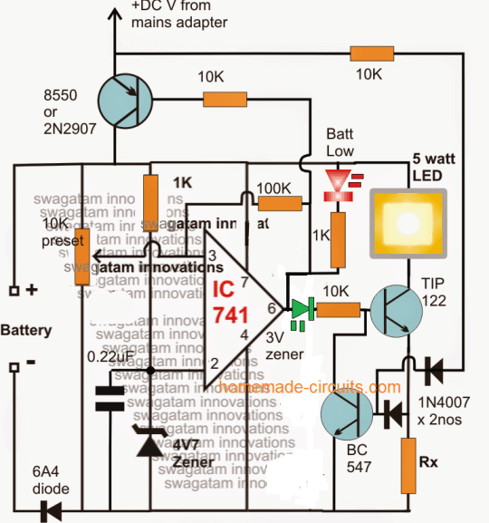
In this post I have explained about a simple yet sophisticated automatic emergency light circuit which can be considered "smart" due to the involved advanced features and an inexpensive design. The idea was requested by Mr. Lokesh.
Technical Specifications
Hi sir, I am so glad to see your interest towards electronic circuits. So eagerly waiting for circuit which will be having following (few or all) feature.
- Low Battery Cut-off
- Overloading protection
- Short Circuit protection
- Reverse current protection
- Reverse polarity protection
- Thunder protection
- Over discharge protection
- Auto battery shut-off at Low voltage detection
- Overcharge protection
- Auto charge stop/ High Volt Detection
- Battery capacity level display(SOC)
Making this circuit for underprivileged location as donation for poor via charity So hope I can have one ckt diagram with some or all features mentioned above or lts link..
Looking for your reply ..
With full excitement
Thank you
Regards
Lokesh
If successful I am in plan to put ur & website name on my device 🙂
As part of tribute to you sir
The Design
Amongst the many interesting features requested above only two are not included in the proposed smart LED emergency light circuit which are: 1) Battery Capacity level indicator, and 2) thunder protection.
The battery capacity level indicator is eliminated to keep things simple in the design, and the thunder protector feature is not considered in the circuit since it may be included in the form of an external attachment and cannot be a part of the electronic circuit.
Apart from the above all the remaining features are included in the design making it a truly impressive and a smart.
So I have explained the simple yet advanced design in detail with the help of the following description:

Referring to the above shown smart automatic emergency light circuit, the IC 741 forms the battery level detector and the cut off stage.
How it Works
The 10k preset is adjusted such that the output of the IC goes just positive whenever the "full battery" is reached at the selected level
This is indicated by the illumination of the green LED and the shutting off of the red LED. When this is detected the IC goes into a latching mode due to the presence of the 100k feedback resistor.
Since this 100k resistor also forms the hysteresis control and becomes responsible of restoring the charging process at the desired low battery level, it must be so selected that it executes this low charge restoration process at the correct preferred low battery level.
During the absence of mains power, when the low level is detected by the opamp, the TIP122 is instantly switched OFF to prevent over discharging of the battery.
The transistor TIP122 becomes the LED driver device, which triggers ON into a standby mode as soon as the battery gets fully charged, and switches ON the LED in case the mains power fails.
Calculating the Current Limiter
The associated BC547 transistor ensures a safe, restricted current to the LED as set by the value of the resistor Rx.
Rx is calculated with the help of the following formula:
Rx = 1.2 / LED max safe current (in amps)
The PNP transistor on top is positioned to supply the charging voltage for the battery. It is enabled in the switch ON position whenever the battery voltage is detected to be below the lower threshold and while the opamp output is rendered negative or low, on the other hand this PNP transistor is instantly switched OFF when the battery is detected to be fully charged and the opamp output toggled to a high or a positive potential.
The supply voltage at the collector of this transistor may be derived from any standard SMPS AC/DC adapter unit.
The feed back link from the collector of the PNP transistor to the base of the BC547 takes care of the emergency LED changeover action, which ensures an immediate, automatic switch ON of the LED whenever the grid voltage fails and vice versa.
If you have any further questions regarding the design, you may feel free to use the comment box below to jot in your valuable feed backs.