This can be a perfect circuit project for Halloween, although sound activated gadgets likewise may have plenty of other applications.
When somebody enters the Halloween house, a sensitive MIC detects the sound vibrations and spins the eye balls of the scary looking beard man, as if it was waken up by the sound, and is not happy with it.
A pair of green LEDs inside the nostrils of the head enhance the creepy feeling, especially in a dimmed illumination.


Working Concept and Block Diagram
The circuit engages a tiny mic which flips a couple of eyes within a scary looking head, to snap them open for a short period of time, and then close them again.

Referring to the above block diagram, sound vibration is detected through the mic, and boosted through a basic opamp pre-amplifier. The the op-amp output is rectified (meaning transformed from a.c. to d.c.) and applied to control a Darlington power amplifier. As soon as the power amplifier triggers on, a substantial amount of current moves through the solenoid and the LEDs.
Circuit Description
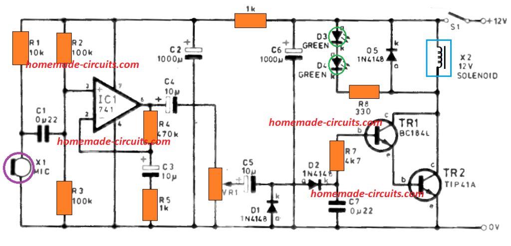
The mic is undoubtedly an electret type, which is tiny, low-cost, and specifically very sensitive. As opposed to regular dynamic varieties this works with a d.c. supply, which is supplied through R1 as shown in the below figure.
The low alternating electric current coming from the mic is supplied through C1 on the non inverting input of IC1.

Because resistor R4 feeds back the output signal of the op amp with the inverting input, the AC content gets eliminated. On the other hand, capacitor C3 gives an AC connection to 0V through R5.
At this point the only portion of the a.c. output shows up on pin 2, and the output is therefore moderately lowered. The R4 to R5 divider fixes the average optimum a.c. gain reached by the circuit.
Solenoid Driver Working
The a.c. frequency travels through C4 to VR1 . The setting of the VR1 slider fixes the signal level fed across the following stage.
Diodes D1 and D2 work as a voltage doubler and rectifier, which charges the capacitor C7 to some d.c. voltage point, depending on the voltage level of the a.c. signal moving through C5. The C7 value decides the amount of time for which the Halloween eyes stay open once the sound has ended.
Resistor R7 controls the C7 discharge into the transistors TR1 and TR2, configured as a Darlington couple. The gain attained is calculated by the product of TR1 and TR2 gain.
Once the Darlington pair activates, current begins flowing through the solenoid, and by means of TR2 to 0V. The D3 LED is connected in series with D4 and current limiting resistor R8.
Diode D5 inhibits harm induced on the transistors by way of back e.m.f. created by the solenoid.
Decoupling Solenoid Back EMF
The solenoid for this sound activated Halloween eyes project works with a rather huge current, which can lead to voltage imbalances disturbing the functioning of the vulnerable pre-amplifier.
Resistor R6 is introduced to partially segregate the power lines from the pre-amplifier and power amplifier sections. Capacitor C2 guarantees a stable source voltage for the pre-amp, and C6 delivers basic decoupling for your circuit.
Construction Hints
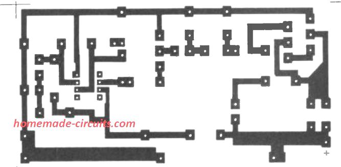
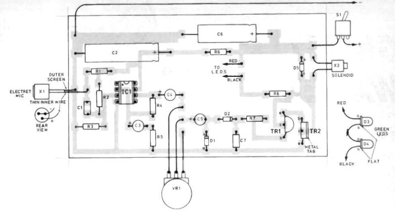
The circuit is built over a PCB presented in the figure below. Start by soldering the small sized elements and IC socket.


Verify that the diodes and transistors are installed the right way round, and a BC184L is employed for TR1, instead of a BC184 which contains pinouts in some other order.
Capacitors C2 and C6 are usually axial forms, that rest flat on the PCB surface. Make sure that capacitors C2, C3, C4 and C6 are fixed the right way round. Attach wire pins for the mic, LEDs, solenoid and power accessory.
Switch S1 could be avoided in case the circuit is to be driven from a mains adapter device. Last but not least press the 741 IC straight into its socket, making certain that pin#1 sits in the right spot. This IC is not really sensitive to static electricity, and therefore could be touched without having any safety measures.
The Enclosure
Almost any form of casing could be used for this sound activated Halloween project; many constructors could choose to bracket the circuit over a wooden block, having the mask completely covering the circuit.
Nevertheless, the prototype had been structured around a typical plastic-type case, that enclosed the circuit, solenoid and batteries. Each of the cumbersome mechanized components had been subsequently bolted, allowing the disguise to be fixed afterwards.
Start by drilling holes for your solenoid armature screw, solenoid installation wedge, axle clamps, VR1, S1, and the pins for the LEDs and microphone.
The PCB could be mounted by using self-adhesive p.c.b. holders. The majority of solenoids facilitate a screw (e.g. size M6) to be appended into the soft iron armature.
Solid nylon string can now be employed to join the screw with the axle that encloses the "Halloween eyes" set up using table-tennis balls.
The solenoid should be installed very cautiously, by using a compact wooden block as indicated. It should afterward be hooked up to the circuit, using the wires without paying attention to the polarity.
Making the Halloween Eyes
The eyeballs are created using table tennis (ping-pong) balls which must be connected with the solenoid mechanism as displayed in the following figure.

Slots must be created on the table tennis balls, to ensure they generate a snug fit around the solenoid axle. The chord or the string tied to the solenoid armature results in the balls to turn in one particular direction, while the elastic string drags them back again. Selfadhesive tape could be used to attach the chords to the axle.
The Halloween "eye" movement limit is determined by the solenoid shaft sitting alongside the upper surface of the box. While the eyes are in the closed position, the shaft should be completely drawn into the case and with the eyes in the open position the shaft should be extended upward.
Long insulated wires must be soldered on the PCB on the LED points, and inserted via the drilled holes in the enclosure for connecting the LEDs. Make sure the LEDs are attached with the right polarity. Using colored wires which might help prevent connection faults. The LEDs may then be pressed into the slots drilled on the mask, right before the mask is mounted into position.
MIC Specifications
The mic could be inserted inside the enclosure, although there can be a risk that it could detect noises from the solenoid causing the mechanism to be continuously activated.
The best possible placement may be under the enclosure, just at the rear of which is supposed to be the beard of the Devil.
In this situation a shielded cable must be employed to link the mic with the circuit. A number of vendors supply microphones with shielded wire fitted by default, yet normally stick to the details as shown above very carefully to make sure that the microphone is attached in a perefct manner.
Power Supply Specifications
A group of 8 nos 1.5 V (AA type) cells can be used for the power source.
Having said that, for long usage a mains adapter may be utilized; however make sure to pick an adapter that may provide sufficient CURRENT to push the solenoid. Approximately 500mA had been used in the prototype.
The adapter does not need to be regulated type, considering that virtually any voltage from 12V and 20V is acceptable. Nonetheless, voltage variations could cause the circuit to be unpredictable, causing the devil's eyes opening and closing randomly!
This can be remedied by making use of either a correct voltage regulator, a power supply with a much larger current output, or a very big filter capacitor along the DC supply lines. Try things out to reach the most effective results!
Need Help? Please Leave a Comment! We value your input—Kindly keep it relevant to the above topic!