Many a times we find it crucial and handy to possess a true three phase signal for evaluating many different electronic configurations such three phase inverters, three phase motors, converters etc.
Since it's not so easy to incorporate single phase to three phase conversion quickly we find this particular implementation difficult to acquire and enforce. The proposed circuit enables the above discussed well calculated spaced and positioned sine waves outputs to be generated from a single master input source.
Circuit Operation
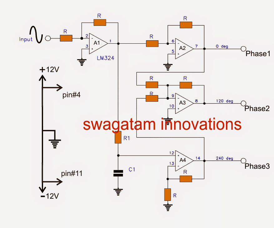
The circuit functioning of the three phase waveform generator circuit may be understood with the help of the following explanation:
An input sine sample waveform is fed across the point "input" and ground of the circuit.This input signal gets inverted and buffered by the unity gain opamp A1. This inverted and buffered signal acquired at the output of A1 now becomes the new master signal for the forthcoming processing.
The above buffered master signal gets once again inverted and buffered by the next unity gain opamp A2 creating an output with zero degree initial phase across the points "Phase1"
Simultaneously, the master signal from A1 output is phase shifted by 60 degrees via the RC network R1, C1, and fed to the input of A4.
A4 is set up as a non-inverting opamp with a gain of 2 in order to make up for the signal-loss in the RC configuration.
On account of the fact that the master signal is phase shifted 180 degrees from the input signal, and further shifted to an additional 60 degrees by the RC network, the ultimate output waveform gets shifted by 240 degrees, and constitutes the "Phase3" signal.
Now, the next unity gain amp A3 sums up the A1 output (0 degrees) with A4 output (240 degrees), creating a 300 degree phase shifted signal at its pin#9, which is in turn inverted appropriately, shifting the phase to an extra 180 degrees, creating the intended 120 degree phase signal across its output indicated as "Phase2".
The circuit is intentionally wired up to work with a fixed frequency in order to yield better accuracy.
Fixed values are used for R1 and C1 for rendering the intended, accurate 60 degree phase shifts.
For specific customized frequencies, you may use the following formula:
R1 = (√3 x 10^6) / (2π x F x C)
R1 = (1.732 x 10^6) / (6.28 x F x C1)
where:
R1 is in kohms
C1 is in uf
Circuit Diagram
Parts List
All R = 10 kohms
A1---A4 = LM324
Supply = +/- 12vdc
| Frequency (hz) | R1 (kohms) | C1 (nf) |
|---|---|---|
| 1000 | 2.7 | 100 |
| 400 | 6.8 | 100 |
| 60 | 4.7 | 1000 |
| 50 | 5.6 | 1000 |
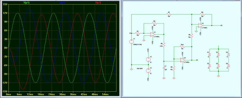
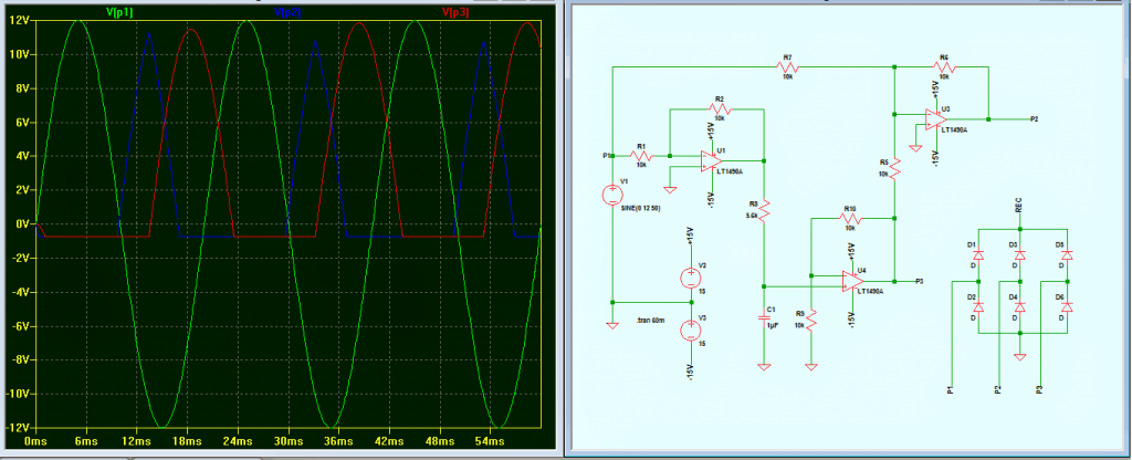
The above design was investigated by Mr. Abu-Hafss and appropriately corrected for obtaining legitimate responses from the circuit, the following images provide a detailed info regarding the same:
Feedback from Mr. Abu-Hafss:
I needed a 15VAC 3-phase supply to test 3-phase rectifiers. I simulated this circuit the other day but failed to get proper results. Today, I made it work.
IC A2 and resistors connected to pin 6 could be eliminated. The resistor between pin 7 and 9 could be connected between the main input and pin 9. Phase-1 output can be collected from the original AC input. Phase 2 and 3 can be collected as indicated in the circuit.
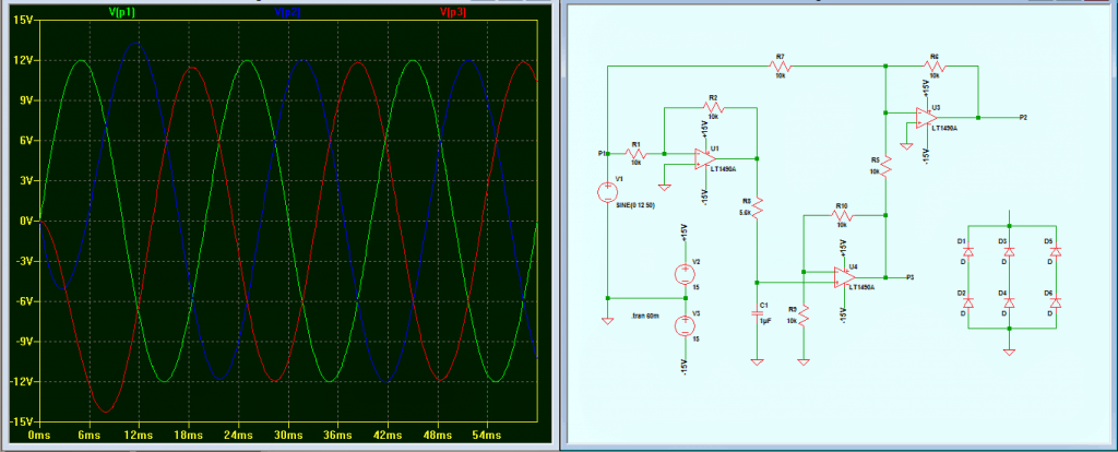
However, my actual requirement could not be fulfilled. When these 3 phases are connected to a 3-phase rectifier, the wave form of phase 2 and 3 gets disturbed. I tried with the original circuit, in that case all three phases gets disturbed
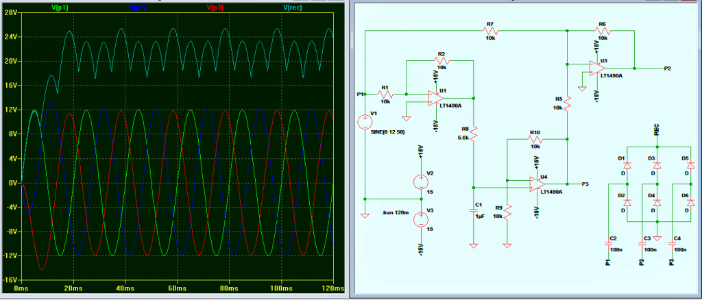
Finally got a solution! A 100nF capacitor connected in series with each phase and the rectifier solved the problem to a great extent.
Though the rectified output is not consistent but, it is quite acceptable
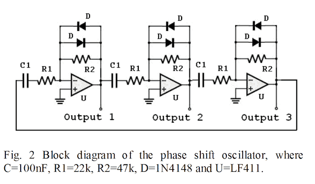
Update: The following image shows a much simpler alternative for generating 3 phase signals with accuracy and without complicated adjustments:
