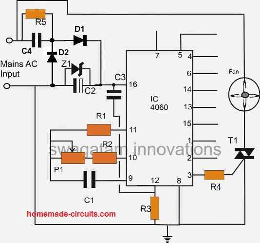
This simple timer oscillator circuit can be used for automatically switching an exhaust fan ON/OFF as per a fixed predetermined period. The circuit was requested by Mr. Anshuman.
Technical Specifications
Here is a suggestion for the circuits on your blog. The idea is to have a very simple Oscillating circuit will delays of 5-10 minutes to turn on and off exhaust fans which would otherwise go bad if left on by mistake.
Ideally this circuit should be small enough to fit behind the switch itself …I was thinking of a couple of RC delays with a transistors to do the oscillation and a simple relay to be operated which will operate the AC Fan itself.
Of course we will need a very very basic rectifier to make the DC to power the circuit…unless somehow this can all be done ALL in AC and I'm missing something.
Please drop me a reply if you are able to find the time to work this or let me know if you post it on the blog.
Regards,
Anshuman
The Design
As shown in the figure below, the proposed exhaust fan timer oscillator circuit may be understood as follows:
D1, D2 along with C2, Z1 and C4 forms a standard transformerless power supply which provides the circuit with the required operating DC voltage.
D1 rectifies the AC half cycle while D2 allows the C4 capacitor to discharge during each AC half cycles so that the capacitor can deliver the power on the next half cycle. Without D2 the capacitor will charge once and get permanently blocked.
Z1 regulates the voltage to a constant 15 V.
C4 helps to limit the AC current to 20 mA and C2 filters the regulated DC into a smooth DC.
The IC 4060 is a counter, divider chip which has a built in oscillator. Here it is configured as an oscillator whose timing is determined by the setting of P1 and the value of C1.
When power is switched ON, the circuit receives the required DC supply for initialization.
Current through C3 instantaneously resets the IC pin#12 so that the timing can begin from zero and not randomly.
Pin#3 which is specified to give the highest delay switching is wired as the trigger output for the connected triac load assembly.
Initially as the timer counts, this pin is held at logic zero.
As soon as the timing elapses, the above pin goes high triggering the triac and the connected load which is an exhaust fan here.
The situation persists until the ON time of the circuit elapses reverting the output to zero and switching OFF the load.
The above cycle repeats, switching the load ON/OFF at the predetermined time rate as long as the circuit remains powered..
The circuit can be made into a one-shot timer by inserting a 1N4148 diode across pin#3 and pin#11 of the IC (anode to pin#3, and cathode to pin#11)

Parts list for the above exhaust fan timer/oscillator circuit
- R1, R3 = 100K
- R2, R4 = 1K
- R5 = 1M
- C1 = 1uF/25V
- C3 = 0.1uF disc
- C2 = 100uF/25V
- C4 = 0.33uF/400V
- Z1 = 15V 1watt zener
- D1, D2 = 1N4007
- T1 = BT136