The TIP122 is an NPN Darlington pair transistor that is commonly used in power switching applications. It has a high current gain and can handle up to 5A of continuous current.
Here is the complete datasheet for the TIP122 transistor:
Electrical Characteristics (Do not exceed these specifications):
- Collector-Base Voltage (VCBO): 100V
- Collector-Emitter Voltage (VCEO): 100V
- Emitter-Base Voltage (VEBO): 5V
- Collector Current (IC): 5A
- Base Current (IB): 5A
- Power Dissipation (PD): 65W
- DC Current Gain (hFE): 1000 (min) at IC=3A, VCE=4V
- Switching Speed: 3MHz (typical)
Package Type:
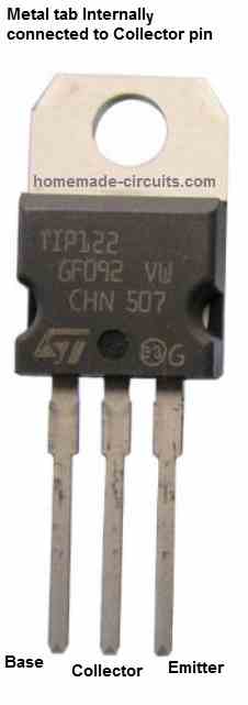
The TIP122 transistor is available in a TO-220 package, which is a standard three-lead package with a metal tab for heat dissipation.
Pin Configuration:
As shown in the diagram, the TIP122 transistor has the following three pins:

- Pin 1: Base
- Pin 2: Collector
- Pin 3: Emitter
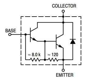
The internal Darlington configuration of the transistor is as shown below:

Applications:
The TIP122 transistor is commonly used in power switching applications such as:
- DC motor control
- Solenoid control
- Lamp control
- Relay control
Simplest Solar Charger Application Circuit
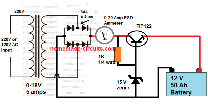
The following image shows how TIP122 transistor can be used to build a simplest solar charger circuit:

The output voltage is calculated using the following formula:
Vout = zener value - TIP122 forward drop
= 15 - 1 = 14 V
The TIP122 here is configured as an emitter follower, therefore its forward voltage drop will be approximately equal to 0.6 + 0.6 = 1.2 V. The double 0.6 V is due to the Darlington transistor, each dropping around 0.6 V.
Note: This datasheet is for reference only. Please refer to the manufacturer's datasheet for complete specifications and characteristics of the device.
Need Help? Please Leave a Comment! We value your input—Kindly keep it relevant to the above topic!