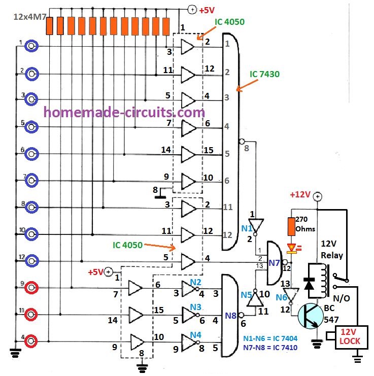
This touch operated electronic door lock can be used for locking any entrance through a touch keypad. The lock's touch feature is foolproof and impossible to crack since the touch function is required to be on 3 programmed pads together or simultaneously, otherwise the lock doesn't respond.


It is a lot convenient to open a door using a code lock as compared to carrying weighty metal keys with us. Aside from this, traditional keys can easily get misplaced, but this cannot happen with code locks.
Advantage of Touch Operated Code Lock
The circuit diagram below exhibits a code lock that enables it to be opened through an effective three-digit code. But, this specific lock performs this function in a somewhat unconventional and unique technique. In this system, 3 digits has to be touched concurrently, meaning three fingers must touch 3 designated code buttons simultaneously.
Any one finger touching the incorrect button would simply not allow the relay to actuate. As the diagram distinctly indicates, it is actually out of the question for an intruder to speculate from the lock's layout exactly how it can be decoded.
This particular characteristic, alongside the huge range of combination possibilities, causes it to be extremely hard for an onlooker to crack the lock code. Another advantage is, involving 3 fingers together helps to cover the keyboard and hides the code operation from an onlooker, and the person finds it extremely difficult to understand which 3 pads were tapped by the owner.

How it Works
In all 5 CMOS ICs are used here. All the gates from the IC 4050 are used as buffers whose inputs can be seen connected with the touch keypads.
These buffers ensure that the touch operation are effectively converted into logic output signals without any malfunction. Because our finger may have varying resistance levels and pressure causing the output to oscillate and generate fluctuating outputs. The buffers ensure this never happens regardless of the touch variation.
The only criterion being the code number which must be touch simultaneously without fail for the lock to open.
The output from the buffers are further wired with Hex Inverter IC 7404 and the processor ICs 7430, 7410 which finally execute the relay activation when the code is correctly tapped. An electronic door opener may be configured with the relay contacts for implementing the lock opening and closing operations.
The code for the shown circuit illustration is 9-11-4. Any time this program code pads are simultaneously tapped with fingers, the inputs of N2, N3 and N4 turn logic '0'; consequently, the three inputs of N8 and the output of N5 create a logic '1'. Assuming none of the other keypads are tapped except the coded ones, all inputs of gate N7 remain logic '1', which results in the relay to become activated and the LED to illuminate. The relay can be employed to operate an electric door opener mechanism for opening the lock.

Have Questions? Please Leave a Comment. I have answered over 50,000. Kindly ensure the comments are related to the above topic.
sorry i pushed the wrong sequence of buttons, it works
the combination of the push buttons for activating the relay do not work, but the led stays on
Sir, could you please give a more detailed explanation of the above circuit, with more input cases…
Saptarishi, sorry more input buttons cannot be added in this design
Sorry sir, I just need some more details about the above circuit. For instance how does the touch mechanism work? Do we use some sort of a sensor for all 12 input ports? I can imagine using switches to create logic signals. But how do I implement touch? Also when the user touches all three keys simultaneously, how is the input logic 0?
I am using this circuit design for my college project, looking forward to your response!
Saptarshi, no sensors are required at the touch-pads, rather sensing is achieved by bridging the ground line and the gate input point together through our low finger resistance.
Grounding the three sensors with fingers will cause the inputs of the buffer gates to be almost zero voltage, or logic zero….this will be further transferred by the buffers to the inputs of N2, N3, N4 as perfect logic zeros
Hi, please forgive me for sending my question through this page if not on topic. I went to your Contact page but I didn’t find a comment text box.
I would like to ask for links to projects you have already done that will help me build a simple burglar alarm. My alarm should have an arm/disarm/ circuit, an alarm loop with simple magnetic contacts and a 12 VDC output to drive a relay. I plan to use a radio transmitter to toggle the Arm mode on and off. I already have a 3rd party transmitter/Receiver to use as the remote arming.
I am sure you already have a project that I can adapt to my project. Please send links to any project that can help.
Thanks, Stephen Hammock
Macon, Georgia
USA
I appreciate your concern, and I will try my best to solve your query. Presently i do not the exact circuit specified by you, but I will try to design it for you soon and let you know once it is completed.
Hai Sir,
What is to be considered when using a peizoeelctric sensor as a switch? I want to develop a circuit for peizoelectrc sensor based touch switch.
Thankyou
Hi MTech, piezo electric transducer will generate a pulse output of a few volts when knocked sharply. The voltage output will be proportionately lower depending on the power of the knock. So based on this you can build an amplifier and a flip flop for the switching action.
thankyou