Connecting transistors in parallel is a process in which the identical pinouts of two or more transistors are connected together in a circuit in order to multiply the power handling capacity of the combined parallel transistor set.
In this post I have explained how to safely connect multiple transistors in parallel, these can be BJTs or mosfets, I will elucidate both.
Why Parallel Transistor become Necessary
While making power electronic circuits, configuring the power output stage correctly becomes very crucial. This involves creating a power stage that can handle high power with least effort. This usually is not possible using single transistors, and requires many of them to be connected in parallel.
These stages primarily may consist of power devices like the power BJTs or MOSFETs. Normally, single BJTs become sufficient for getting moderate output current, however when higher output current is required, it becomes necessary to add more number of these devices together. Therefore it becomes necessary to connect theses devices in parallel. Though using single BJTs is relatively easier, connecting them in parallel needs some attention due to the one significant drawback with transistor characteristics.
What is "Thermal Runaway" in BJTs
As per their specs, transistors (BJTs) need to be operated under reasonably cooler conditions, so that their power dissipation does not exceed the maximum specified value. And that's why we install heatsinks on them to maintain the above criterion.
Moreover, BJTs have a negative temperature coefficient characteristic which force them to increase their rate of conduction proportionately as their case temperature increases.
As its case temperature tends to increase, the current through the transistor also increases, which forces the device to heat up further.
The process gets into a kind of chain reaction heating the device rapidly until the device becomes too hot to sustain and gets permanently damaged. This situation is called thermal runaway, in transistors.
When two or more transistors are connected in parallel, due to their slightly differing individual characteristics (hFE), the transistors in the group may dissipate at different rates, some a little faster and others a little slower.
Consequently, the transistor which may be conducting slightly more current through it might start getting heated up faster than the neighboring devices, and soon we may find the device entering into a thermal runaway situation damaging itself and subsequently transferring the phenomenon to the remaining devices as well, in the process.
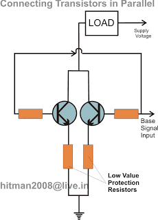
The situation can be effectively tackled by adding a small value resistor in series with the emitter of each transistor connected in parallel. The resistor inhibits and controls the amount of current passing through the transistors and never allows it to go to dangerous levels.
The value should be appropriately calculated, as per the magnitude of the current passing through them.
How to connect Bipolar Transistor in parallel
The following circuit diagram shows how to correctly connect two or more transistors in parallel. The emitter resistors make sure that the current sharing across the transistors is uniform and thus a thermal runaway situation is avoided.

How to Calculate the Emitter Current Limiting Resistor in Parallel BJTs
It is actually very simple, and could be calculated using Ohm's Law:
R = V/I,
Where V is the supply voltage used in the circuit, and "I" could be 70% of the transistor's maximum current handling capacity.
For example let's say if you used 2N3055 for the BJT, since the max current handling capacity of the device is around 15 amps, 70% of this would be around 10.5 A.
Therefore, assuming the V= 12V, then
R = 12/10.5 = 1.14 Ohms
Calculating the Base Resistor
This can be done using the following formula
Rb = (12 - 0.7)hFE / Collector Current (Ic)
Let's assuming hFE = 50, Load current = 3 amps, the above formula could be solved as under:
Rb = 11.3 x 50 / 3 = 188 Ohms
Considerations
To calculate the parameters safely we must take care of the following considerations:
Current Sharing with Emitter Resistors:
- The voltage drop across each emitter resistor is supposed to be approximately equal.
- The value of the emitter resistors can be calculated with regards to the desired current and the voltage drop across them.
Thermal Considerations:
Power Dissipation: Calculate the power dissipation of each transistor using the formula:
P = VCE * IC
Junction Temperature: Estimate the junction temperature using the thermal resistance of the transistor and the heat sink:
Tj = Ta + (Pd * θJA)
- where:
- Tj: Junction temperature
- Ta: Ambient temperature
- Pd: Power dissipation
- θJA: Junction-to-ambient thermal resistance
How to Avoid Emitter Resistors in Parallel BJTs
Although the use of emitter current limiter resistors looks good and technically correct, a simpler and a smarter approach could be to mount the BJTs over a common heatsink with a lot of heatsink paste applied to their contact surfaces.
This idea will allow you to get rid of the messy wire-wound emitter resistors.
Mounting over a common heatsink will ensure quick and uniform sharing of heat and eliminating the dreaded thermal runaway situation.
Moreover since the collectors of the transistors are supposed to be in parallel and joined with each other, the use of mica isolators no longer become essential and makes things much convenient as the body of the transistors get connected in parallel through their heatsink metal itself.
It's like a win-win situation...transistors easily combining in parallel through the heatsink metal, getting rid of the bulky emitter resistors, a well as eliminating the thermal runaway situation.

Connecting MOSFETs in Parallel
In the above section I have explained how to safely connect BJTs in parallel, when it comes to mosfets the conditions become entirely the opposite, and much in favor of these devices.
Unlike the BJTs, mosfets do not have the negative temperature coefficient problems, and therefore are free from the thermal runaway situations due to overheating.
On the contrary, these devices exhibit a positive temperature coefficient characteristics, meaning the devices begin conducting less efficiently and begin blocking current as it begins getting warmer.
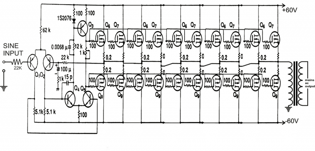
Therefore while connecting mosfets in parallel we do not have to worry much about anything, and you may simply go ahead hooking them up in parallel, without depending on any current limiting resistors, as shown below. However using separate gate resistors for each of the mosfets should be considered....although this is not too critical..

Important Considerations for MOSFETs
For connecting MOSFETs in parallel we must consider the following parameters for increased safety and higher efficiency from the devices:
Power Dissipation:
P = Vds * Id
- where:
- P: Power dissipation (Watts)
- Vds: Drain-source voltage (Volts)
- Id: Drain current (Amps)
MOSFET Parameters:
On-Resistance (Rds(on)): The combined on-resistance of parallel MOSFETs is:
Rds(on)total = Rds(on)individual / N
- where:
- N: Number of parallel MOSFETs
Gate Charge (Qg): The total gate charge can be found by adding the sum of the individual gate charges:
Qg(total) = N * Qg(individual)
Conclusion
In the above post we elaborately learned how to connect transistors in parallel. We can summarize the procedure as I have explained below:
When bipolar transistors are connected in parallel, always make sure to add a calculated emitter resistor for each transistor. This resistor enables the BJTs to share the load current and thermal dissipation uniformly, which solves the thermal runaway problem in BJTs
If you want to avoid the emitter resistors, you can consider mounting the transistors closely, over a single common heatsink, so that the heat dissipation is shared uniformly and a thermal runaway situation is avoided.
For MOSFETs no source resistors are required because MOSFETs are negative coefficient transistors and a thermal runaway situation is not applicable to these devices.
However still, to ensure high efficiency from the parallel MOSFETs it is recommended to mount them over an adequately rated heatsink.
