In this article I have explained how to make any BJT or mosfet based circuit free from stray signal pickup and false triggering by simply attaching a filter resistor or a capacitor across their base/emitter or gate/source terminals. The problem was raised by Mr.Henrik.
Solving a Circuit Problem
I have an issue I don’t understand. please check out the following diagram.

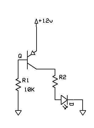
If I connect the Base of a PNP transistor through a 10K resistor to ground the LED lite up. If I disconnect the Base from ground the LED light up weakly. I would have expected the LED to be completely off.Can you explain me why this is the case. I have tried with other transistors also.
If I use a NPN transistor to switch a PNP transistor (Darlington) do I need a resistor from the Base of the PNP to Collector of the NPN transistor?
Thank you,Henrik
The Reason behind the Fault:
The mentioned problem of false transistor triggering while its base was unconnected to a triggering source may be due to stray signal pickup by the transistor base causing the slight illumination on the LED.
Because as we know that when a small current flows through base emitter of a BJT, forces a relatively more stronger current to pass through collector/emitter of the device. Here too the stray signal at the base of the BJT could be forcing the device to trigger albeit fractionally, but enough to cause a faint illumination on the LED.
The Solution:
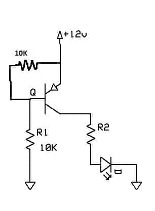
The problem could be easily remedied by adding a compensating resistor across the base emitter of the BJT, the value could be anything which allows a 1V across the base emitter when the actual trigger is connected with the base. This value could be evaluated using a resistor potential divider network calculation.
Or simply a matching value resistor could be included similar to the existing base resistor value, as done below.

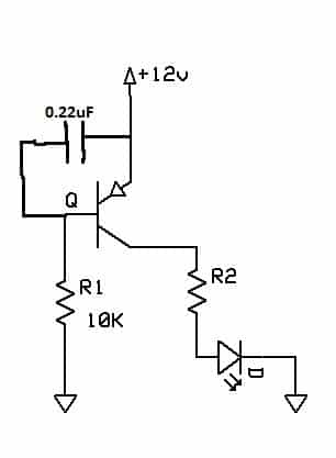
Another simple way to eliminate stray pick up while its base was not associated with any form of input logic or trigger is to add a small value capacitor across its base and emitter, which would help the BJT to effectively ground any possible stray input signal and prevent it from causing the device to conduct spuriously.

please give difference of pull up and pull down resistance and above theory.
I want theory to prevent false LED indication of
any circuit diagram. So circuit would be work proper ON and OFF.
Pull-up resistor is connected from positive supply to base of a BJT, when the base of this BJT is connected to a sinking source via the collector of another BJT or through a diode from a logic IC output.
Pull-down resistor is connected between base of the BJT and its emitter supply. It’s basically to add a potential divider network at the BJT base.
Please provide your LED application details, if possible I will try to solve it for you….
Can i connect 220v AC line to base of BC546 through a 5M ohm resistor to trigger the transistor ON/OFF.
The main question is: since the C, E and load is going to b on a DC circuit with a 9V battery, will the domestic line which will not have common ground with this DC circuit trigger the transistor?
Thanks for your advice in advance
You must have the other unused line of the mains connected with the common (-) of the 9V DC otherwise the transistor will not switch. You will have to use a 1N4007 diode in series with the base resistor so that only +DC is able to reach the base.
5M is too high, you can safely use 100K.
This design will be non-isolated from mains so extremely dangerous to touch.