This tiny and simple transmitter, receiver set will allow you to communicate over 100 of miles across the world, by tuning to 80-meter amateur ham radio stations.
What is 80-meter Band
The 80-meter uses 3.5 MHz frequency band for radio communications, which gets the permissions under amateur radio use
Between 3.5 to 4.0 MHz in IARU Region 2 (which mostly come under the range of North and South America), and also typically between 3.5 to 3.8 or 3.9 MHz in Regions 1 and 3 (which accommodates the other countries of the world) respectively.
The upper spectrum of this radio band, is commonly used for phone (voice) communications, and it is often known as 75 meters. In Europe, 75-m is actually a shortwave broadcast band, which may include several national radio stations transmitting between 3.9 and 4.0 MHz frequency spectrum.
If not as ham radio, the discussed designs could be simply tuned up with each other to work as personalized long range walkie-talkie circuit.
How the Transmitter Works
The transmitter circuit is every bit as simple and employs just 3 low-cost BJTs. The input power specs (and therefore the output power specs) is determined by the voltage with which driven. 6 volts input supply might allow an overall input power of 1.2 watts.

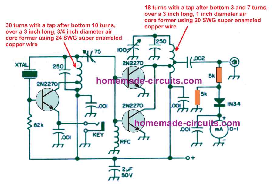
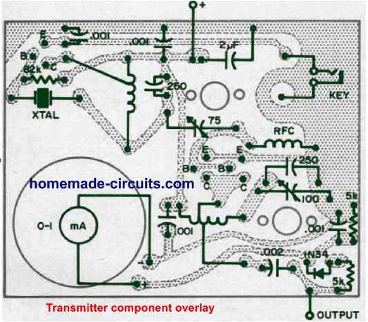
The output Power can be expected to be around 50% of the input power. If you operate the unit with a 12 V supply would allow you get an output of 4 watts power; with 24 volts it will increase to an impressive 10 watts; and in case 40 volts is applied which is maximum that can be used with this design will enable the unit work with a massive 20 watts power output. The transmitter circuit really is easy.
It's a crystal oscillator is configured to work at 3725 kHz accompanied by a class C output amplifier. No heat sinks are needed for the transistors. You can find just a couple of adjustment controls: the oscillator tuning and output tuning. Each of them basically have to be tweaked for optimum reading on the meter.
How to Set up
The transmitter is practically as effortless to use as the receiver circuit. You will have to hook up a resonant antenna to the antenna connector.
An appropriate antenna can be any half wave dipole (12.5 feet in length and separated at the center through an insulator) attached through 50-ohm coaxial cable like the HG-58.
Connect a 6 V to 40 V Dc supply source rated at 500 mA across the power terminals, taking care of the polarity.
Next, plug-in a crystal in the 80-meter amateur band (between 3705 and 3745 kHz). Switch ON the supply and fine-tune the a pair of controls swiftly to obtain highest meter reading, and this will simply put you on the air, transmitting your voice across the 80-meter band, across many miles.
The least difficult strategy to make use of the transmitter and receiver collectively is by using independent antennas. The transmitting antenna should be resonant at the frequency with which it is being operated, however the receiving antenna doesn't need to be too critical with its spec.
Once built and set up you can have lots of fun with this amateur ham receiver and transmitter set, for communicating with your friends miles away.
How the Receiver Works
The receiver circuit covers the portion of the 80-meter band usually intended for transmitting morse code signals, such as the 3700 to 3750 kHz Amateur band.
It actually works great and can easily catch ham stations 100s of kilometers away using a any standard ham antenna. It isolates the signals remarkably effectively, however obviously cannot match up against the higher priced receivers.
The original author checked it with stations across 200 miles apart using this tiny receiver and its partner transmitter. The two are entirely built using just BJTs to get minimal power drain, high consistency, low cost, smaller dimension and ease-of-use.
The receiver is an advanced model of a design which used to be pretty popular in the older times of hamming. It basically consists of a regenerative detector and an audio amplifier.
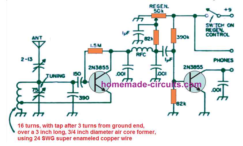
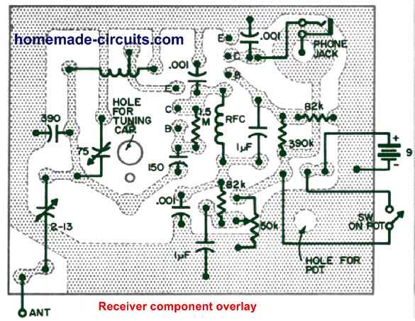
The detector stage is very sensitive and selective with its characteristics. This stage will receives not just code impulses but additionally SSB and AM phone. Any individual accustomed to sophisticated receiver systems, could be amazed with the working ability of this simple receiver circuit.
How to Set up
The receiver unit is also a snap to use. We recommend magnetic headphones of 500 to 10000 ohms impedance. Low impedance headphones built for pocket radios and crystal sets may not do the job effectively.
A length of wire around 30, 90 or 125 feet long could perform like an exceptionally good antenna. Although not found in the circuit diagram, a proper earthing hooked up to the box is suggested for most effective outcomes.
You may tune on the receiver by rotating the regenerative switch control pot clockwise ahead of switch ON "click", until a small whistling audio is heard.
Now, keep tuning around until you start catching some ham stations. If you do this during night time will give to best results and you might quickly begin listening to many of these stations.
Code stations can be heard most commonly, having the regeneration control is adjusted to a point where the detector stage hardly oscillates and every dit and dah becomes audible loud and distinct.
You should be able to listen to numerous very slow stations close to the middle of the tuning range.
These stations will be mostly the amateur radio bands. For those who have a crystal in the amateur band range, it is possible to track down your own personal signals, by broadcasting it from the discussed transmitter. Voice stations on 80 meters are normally available in 2 types: AM and SSB.
AM is ideally received by adjusting the regeneration control pot until the detector stage judt begins oscillating, and allows you to tune in to the SSB quite like the code stations, with the detector stage oscillating.
In case the tuning is done inaccurately, the SSB signals might sound funny, practically like sound of ducks quacking,
The little adjustable capacitor or the trimmer joined between the antenna and tuning coil could be just about any value from 2 to 13 to 3 to 40 pF. The value is certainly not very important, however needs to be tweaked a bit if you find the receiver failing to oscillate correctly.
Another Simple 3.5 MHz Receiver Circuit
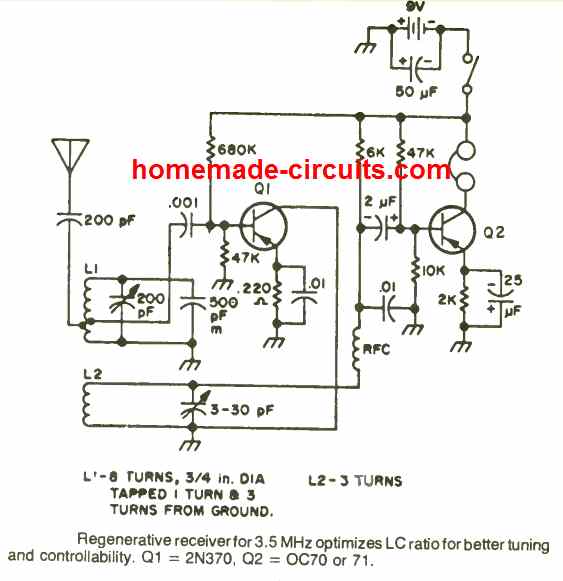
This 3.5 MHz regenerative receiver is designed to self optimize and adjust the LC tank circuit ratio value resulting in an enhanced tuning ans selectivity.
Hi Mr. Swagatam;
When I check the transmitter circuit (like FS1000A) I see the few parts like oscillator 433MHz, 2 coils (3 and 8 turns) and pcs of the transistors etc. Which part is the most crucial for the distance, oscillator or the coils(turns or the diameter)?
Hi Suat,
The output transistor and the antenna are the two elements which mainly determine the range and distance of the transmitter.
Can this unit be used to send and receive morse codes?
Thank you!!
Yes it can be used, according to me.
An impressive share! I’ve just forwarded this onto a coworker who was conducting a little research on this. And he in fact ordered me lunch simply because I stumbled upon it for him… lol. So allow me to reword this…. Thanks for the meal!! But yeah, thanks for spending the time to discuss this matter here on your web page.
Congratulations Swagatam for your contributions. Is the 80 meter transmitter audio or just morse? What modifications must be made to the transmitter and the receiver to use them in 40mts.
Thank you
very much Victor from Chile, South America
Thank you Victor, according to me, the circuit can be used to transmit and receive music signals also. For 40 meters you may have to modify the respective antenna coils which can be slightly difficult.
Hi Swagatam;
I will chechk the details and try the above circuit in practice. I think by adding the pic IC loaded like 16f628a it is possible to transmit various commands to receiver. Meanwhile please advise if it is possible to solve tv remote control protocol codes.-Thanks
Hi Suat, you an surely check the details, and hope it works for you! Since I am good with microcontrollers so can’t suggest much about the question that you have asked
i feel tv remote control can be used for program code and and decode but it needs joint effort to study codes it generates then advance