In this post I have explained a simple, accurate, high torque treadmill motor speed controller circuit which may be effectively installed in similar units for acquiring PWM controlled variable speed feature. The idea was requested by Mr. Samuel.
Technical Specifications
I've a treadmill whose power failed completely...it had been imported from china and it's like they can't help after negotiating with them..guarantee is only meant in their x-try.
So, am asking, how would you assist me in designing a power supply that will control speed and change of direction of the treadmill movement as well. I'm and forever will be glad for your work.
Looking into the specs of the unit, the switching relays are specified with 10A ratings. I also had a view of the motor and it was written 180Volts on it.
This is the information i got sir. They also had a cautionary notice that the T.Mill shouldn't be run beyond 2hrs continuously. I hope I've given the best for the best.Thanks sir. Stay blessed now and forever! best moments!
The Design
Here's a simple PWM based motor speed controller circuit which can be used for controlling a treadmill speed right from zero to maximum.
The circuit also provides an instant bidirectional stop and reversal of the motor rotation by a single flick of a given switch.
Another interesting feature of this circuit is its capability of sustaining and balancing optimal torque even at lower speeds ensuring a continuous working of the motor without stalling it during extreme low speeds.
The circuit of the proposed treadmill motor speed controller may be understood with the help of the following points:
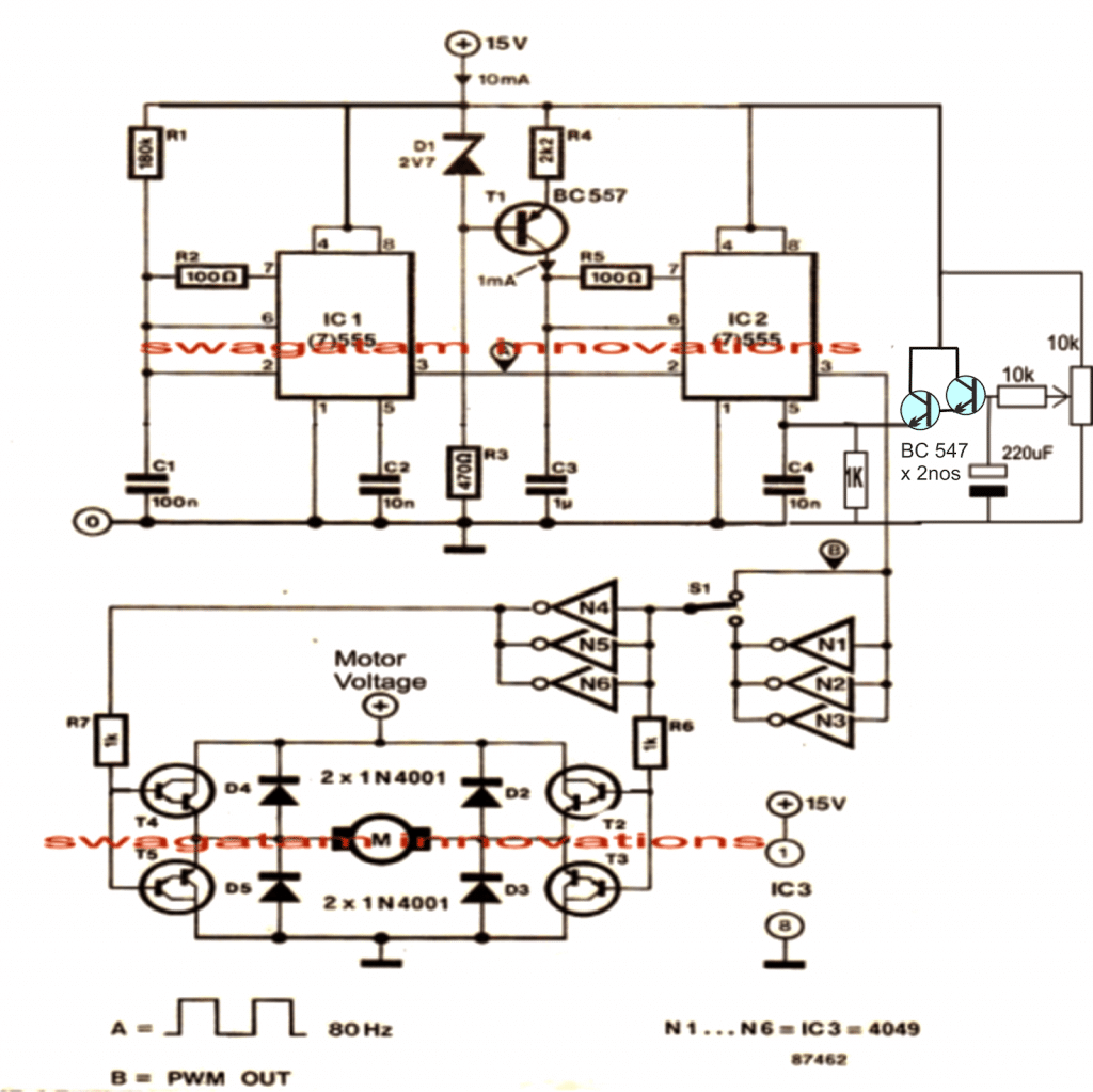
Here the two 555 ICs are configured as PWM generator/optimizer for acquiring the required speed control of the connected motor.
Circuit Operation
IC1 works as a frequency generator and is rigged at around 80Hz, any other value would also do and is not anyway critical.
The above frequency from pin#3 of IC1 is fed to pin#2 of IC2 which is wired as a standard monostable. IC2 responds and starts oscillating at this frequency, forcing equivalent triangle wave frequency at its pin2/6.
The above triangle waves is instantly compared by the set potential at pin#5 of IC2 creating an equivalent level of chopped PWM at its pin#3
The preset or a pot positioned at pin#5 of IC2 forms a potential divider network for a selectable fixing of any voltage from zero to maximum supply voltage at pin5 of IC2. This level is directly translated through optimized PWMs at pin#3 of the same IC as explained above.
The PWMs are fed across two sets of NOT gates via an SPDT toggle switch.
The NOT gates which act as inverters provide the feature of instant toggling of the motors rotational direction by a mere flick of the SPDT switch.
The resultant PWMs from the selected NOT gates finally reach the transistorized bridge network that holds the motor between them for implementing all the specified features discussed above.
These transistors should be rated as per the motor specifications, and the voltage across this bridge should also be as per the motor requirements.

Video Clip:
Simplified Design
If you do not wish to have the reverse forward facility, then you can much simplify the above design by eliminating the lower section of the circuit entirely, as shown below:
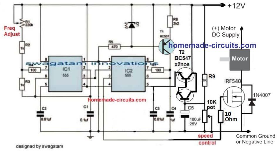
The 10K pot can be used for the speed control, while the 220uF determines the soft start feature. Increasing the 220uF value increases the soft start effect and vice versa.
Controlling Through an External Power Supply
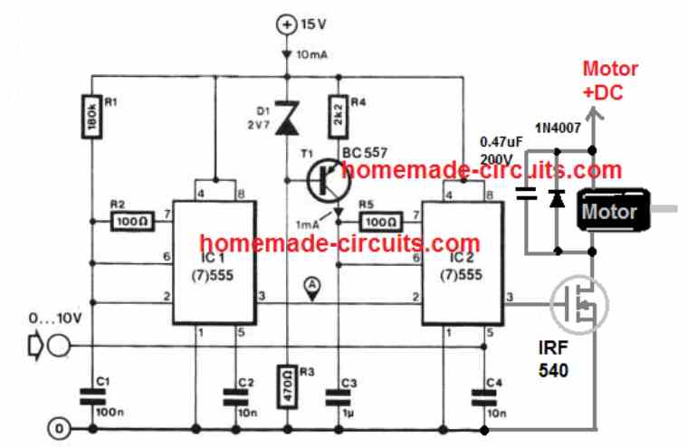
The above design could be also modified for enabling motor speed control through an external variable power supply, as shown below.
Pin#5 can be seen driven from an external 0 to 10V variable power supply, for example from a LM317 based power supply
If you do not wish to use an external power supply, the above treadmill speed controller design could be simplified even further, by adding a 1k pot at pin#5 of IC2, as demonstrated below:
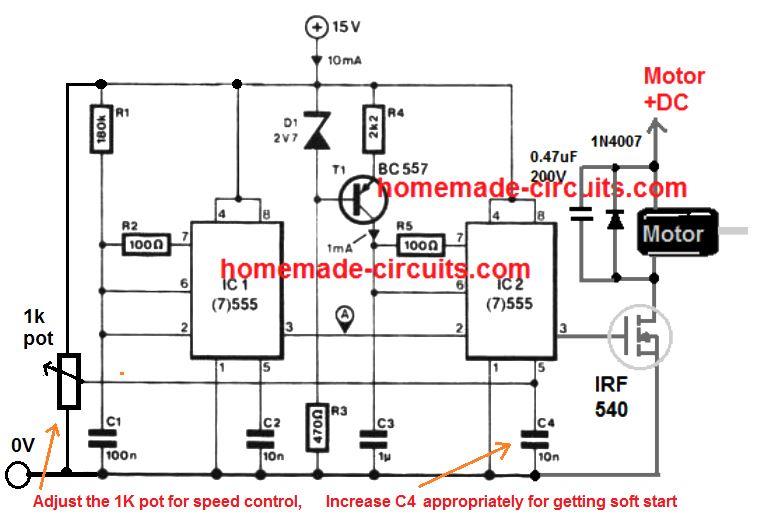
The 1k pot will allow you to adjust the treadmill speed from 10% to 90%, and the C4 value could be experimented to add a nice soft start to the treadmill motor during the switch ON.
Construction Guide
Power Supply Section
15V DC Supply:
Ensure that the input power source delivers a stable 15V DC, because it is critical for the 555 timers and the IRF540 MOSFET operation.
Use a well-filtered power source to avoid the noise interference.
Zener Diode (D1 - 2.7V):
Provides a fixed reference voltage for the base of T1 (BC557 transistor) which gives stable operation.
PWM Generator (IC1 - 555 Timer)
The first 555 timer (IC1) is configured as an astable multivibrator, to generate a pulse-width modulated (PWM) signal.
Pin Connections:
Pin 1 (GND): Connect to the ground.
Pin 8 (Vcc): Connect to +15V supply.
Pin 4 (Reset): Connect to +15V to enable the IC.
Pin 5 (Control Voltage): Add a 10nF capacitor (C2) to ground to stabilize the PWM signal.
Pin 3 (Output): Outputs the PWM signal to the base of T1 (BC557 transistor) via R4.
Frequency Control:
Use R1 R2, and C1 to set the frequency of the PWM signal.
Formula for frequency:
f = 1.44 / [(R1 + 2R2) * C1]Where:
R1 = 180kΩ
R2 = 100kΩ
C1 = 100nF
PWM Adjustment (1kΩ Potentiometer):
The 1kΩ potentiometer varies the duty cycle of the PWM signal allowing the speed control of the treadmill motor.
Soft Start and Motor Driver (IC2 - 555 Timer)
The second 555 timer (IC2), is configured as a monostable multivibrator to implement the soft start feature.
Pin Connections:
Pin 1 (GND): Connect to the ground.
Pin 8 (Vcc): Connect to +15V supply.
Pin 4 (Reset): Connect to +15V to enable the IC.
Pin 5 (Control Voltage): Add a 10nF capacitor (C3) to ground.
Pin 3 (Output): Drives the gate of the IRF540 MOSFET.
Soft Start Capacitor (C4 - 10nF):
This capacitor determines, the ramp-up time for the soft start feature.
Larger values of the C4 increases the soft start time.
Adjust C4 using the formula:
t = 1.1 * R6 * C4Where:
R6 = 10kΩ
C4 = Soft start capacitor
Motor Connection:
The motor is connected to the drain of the IRF540 MOSFET with the source connected to the ground.
D5 (1N4007): Protects the MOSFET from back the EMF generated by the motor.
Working Principle
PWM Speed Control:
The duty cycle of the PWM signal generated by IC1 provides the average voltage applied to the motor.
Adjusting the 1kΩ pot, changes the PWM duty cycle effectively, controlling the motor speed.
Soft Start:
When the circuit is powered ON, the IC2 gradually increases the gate voltage of the MOSFET due to the charging of the C4.
This ensures that motor starts smoothly without jerks.
Overvoltage Protection:
The 2.7V zener diode (D1) ensure the PWM output voltage doesnt exceed safe levels for the transistor T1.
Relevant Calculations
Frequency of PWM Signal (IC1):
f = 1.44 / [(R1 + 2R2) * C1]For the given values:
R1 = 180kΩ
R2 = 100kΩ
C1 = 100nF
Substituting:
f = 1.44 / [(180k + 2 * 100k) * 0.1µF]
f ≈ 34.3 Hz
Soft Start Time (IC2):
t = 1.1 * R6 * C4For the given values:
R6 = 10kΩ
C4 = 10nF
Substituting:
t = 1.1 * 10k * 10n
t = 0.11 ms
If a larger value for the C4 is chosen (e.g 1µF):
t = 1.1 * 10k * 1µF
t = 11 ms
Assembly Tips
Use a Heat Sink for the IRF540:
The MOSFET can heat up under heavy motor loads so Attach an appropriate heat sink.
PCB Design:
Keep the ground connections of the IC1, IC2 and the motor driver separate to avoid noise.
Testing:
Test the PWM output with the multimeter or oscilloscope before connecting the motor.
Safety Precautions:
Ensure proper insulation for all tthe high-current connections to prevent short circuit.
Using A Dimmer Phase Chopper Circuit
As rightly suggested by one of the dedicated readers of this blog, Mr. Ivan, a 180 V treadmill motor can be simply controlled through mains phase chopping concept, normally incorporated in all commercial dimmer switches for regulating home fan speed.
Shown below is a modified dimmer switch circuit design which can be effectively used for regulating a 180 V treadmill motor from zero to max:
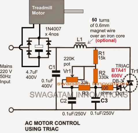
Please make sure to use a non-polar capacitor for the one shown between the bridge rectifier.
Use the following type, 10 in parallel
10nos of 0.47/400V in parallel will make 47uF/400V non polar capacitor which may work like a decent filter capacitor for the motor.
Mr. Swagatam,
I am attempting to build the Treadmill speed control circuit, the second simplified one. Do you have a more clear picture of the circuit? Its a bit blurred and hard to read. I’m wanting to control a 2.5 HP 22 AMP 130VDC PM motor.
Also in the comments its stated to use PPC or metalized type and non polar capacitors. I have not been able to find info as to this type, are they called something different.
Do you have a parts list to go by on this diagram?, that would help a lot too.
I know enough about electronics to safely let out the smoke.
Mr.Clint,
I have updated the post with new simplified diagrams and clearer diagrams, Please check them out!
Part numbers are given in the diagram itself.
All the resistors are 1/4watt 5%
Al the capacitors are PPC type non polar 100V, except the one parallel to the motor which is rated at 200V
Mr Swagatam,
I see no change in the Simplified Design. Just as blurry.
Can you send me directly a very clear diagram.
I can’t see what the transistor number is or what the resistor is above it, barley make out some of the capacitors.
I’m a CAD drafter and would love to redraw some of you circuits for you that need a good clear diagram.
Mr. Clint, Are you seeing the following figures? They are larger and much clearer now:
https://www.homemade-circuits.com/wp-content/uploads/2021/02/tread-mill-control-compressed.jpg
https://www.homemade-circuits.com/wp-content/uploads/2021/02/tread-mill-control.jpg
Yes those are clear but wrong circuit. Its the second circuit in that group. The one after the reversible speed control. I just want to build a one direction speed control.
I also see in both those examples a resistor marked “2k2”. Is that suppose to mean a 2k resistor? The second “2” to me is confusing.
I’ve got a background in electrical controls, so electronics is a bit of a learning curve for me.
The new designs are the simplified versions, they are not wrong!! The following circuit is the simplified version of the second one and will do exactly same like the second one:
https://www.homemade-circuits.com/wp-content/uploads/2021/02/tread-mill-control.jpg
2k2 is 2.2k
I did it the way you told me about the capacitors, it was excellent. I now have a new question … about the coil; what is the ferrite size? for me to do the correct calculation. thank you very much friend.
Glad to know it is solved! The L1 and the complementary C1 are not critical, they are introduced to cancel out the high frequency RF disturbance generated due to the rapid chopping of the phase by the triac!
The coil will need to be experimented with some trial and error. Initially try any ferrite core that will accommodate 100 turns closely wound 21 SWG super enameled copper wire. C1 can be 0.1uF 400V.
Now keep an MW radio nearby and check the reduction of RF by increasing the number of turns on L1. Keep increasing until you find minimum disturbance on the radio.
I’m sorry friend !, I think I couldn’t express myself very well. I replaced the 4.7uf 400v electrolytic capacitor with 10uf and also replaced the 0.1uf400v capacitor with the 22uf non-polarized capacitor and performed the assembly in parallel, overheating still continues. I appreciate your patience in helping me.
No problem friend, I have understood it! The capacitor between the bridge rectifier, can be 4.7uF/400V or 10uF/400V but it should be strictly a non-polar PPC type, just as the other capacitors are.
The 0.1uF/400V does not need to be changed at all, which can cause other problems.
So all the capacitors in the diagram must be non-polar, and the values shown in the diagram must be exactly as it is!
hello friend, I did everything you recommended, replacing the 4.7uf400v capacitor for 10uf 400v is overheating, I put the 22uf capacitor, the heating is very little but if you continue with the 22uf capacitor and the motor will run for another 1 hour or less it can burst. do you suggest me with this situation? I configured the project as shown in the image and I have the omponetes as the project asks.
OK got it, so did you also use a non-polar capacitor as advised by me? Electrolytic cap might not work and may heat up quickly…
Good day. My degree is in Physics, NOT electrical engineering. I have a couple mc2100 board versions and a recent freebee mc1650LS Both need PWM to control motor speed since neither has potentiometer connectors. The 1650 has a 4 pin connector from the upper control board and the other boards have: an RJ45 8 pin, or the 7-8 straight pin. I have seen one mod where a PWM was connected to the 7-8 straight pin connector utilizing just 4 of these pins. While encouraging, none of these searches details, or explains how to connect the PWM generator to any of these boards. I am tempted to just use the SCR + rectifier examples – – but I would really like to utilize the treadmill controller boards. I am just a little lost/overwhelmed… Bill
Hello, I could not find a proper datasheet for the IC MC1650, so I am unable to figure out the pinout details of the IC.
Thans for trying – I ordered a PWM generator off ebay (china) so I don’t expect to see it until May. I looks like it has 4 wire connectors, would you have an idea how to connect this to a mc2100 board? Thanks again.
The MC1200 is actually an SMPS circuit for powering the treadmill motor. It requires an external varying PWM input to enable the corresponding speed variations on the treadmill motor.
You will find a connector near the end opposite to the transformer end of the board. This connector will have four wires, two black common wires which will connect with the negative of the PWM circuit, one red wire that will connect with the positive line of the PWM circuit, and a blue wire that will connect with the PWM signal output of your PWM circuit.
There’s another quick way of achieving the speed control on MC-1200 without using an external PWM. It is by replacing the small yellow colored voltage control preset existing on the MC-1200 board with an identically rated potentiometer.
Hello friend! about the dimmer is working perfectly I mounted it the way you explained to me. I have a new question, I need to set up a project to control a battery-powered 36v 700watt electric bike motor. Do you have a project like this or could you help me with this project? God bless you always my friend.
Hello Elias, glad the dimmer is working correctly now. For a e-bike control circuit you can probably try the following design
Simple E-Bike Circuit [Electric Bike]
yes friend, it is the capacitor that controls the motor. can I replace with a 22uf 450v?
No, the capacitor does not change the speed, the speed is changed by the pot VR1. The capacitor only filters the ripples.
yes 22uF will do, but it should be non-polar to ensure that it does not heat up
I am looking to use this pwm circuit on a conveyor, the engine will work with 1.4hp. 90v. 10A.
I made the circuit and tested it. the 4.7uf 400v capacitor is overheating in the 1.2 hp.90v engine. 10A 4000RPM. Should I change the configuration of this scheme? what did you suggest to me friend?
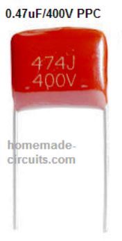
Is it controlling the engine speed? If yes then you can replace the 4.7uF electrolytic capacitor with 5 or 10 nos of 1uF/400V in parallel, these must be PPC or metalized type and non polar, like the brown one in the following image:
Hi, I am hoping to build your 2nd circuit. My motor is rated at 230 Volt DC 9.5 Amp. Will the following Mosfet be suitable?
IXFQ60N50P
Channel Type N
Maximum Continuous Drain Current 60 A
Maximum Drain Source Voltage 500 V
Package Type TO-3P
Mounting Type Through Hole
Pin Count 3
Maximum Drain Source Resistance 100 mΩ
Channel Mode Enhancement
Maximum Gate Threshold Voltage 5V
Maximum Power Dissipation 1.04 kW
Transistor Configuration Single
Maximum Gate Source Voltage -30 V, +30 V
Thank You
John
Hi, yes it should work with the specified circuit design, but first confirm the circuit operation using a 220V bulb, if it dims and brightens with the PWMs then the circuit is working and confirmed.
Hello Swagatam, thanks for all your information. Dimmer Phase Chopper Circuit, 400V 4.7uF and 1500uF 400V capacitor change possible
Hello Hasan, do you mean replacing 4.7/400 with 1500/400…??
yes that’s possible.
I have a conveyor belt that burned her control I can’t find parts for her, the engine works 1.4hp 90v. I really liked your projects. Can you give me a tip? Can I use this scheme to meet the power of this engine?
If your motor is a single phase DC, then the above circuits can be used, provided the input supply is not beyond 110V DC
Yes I wanted to regulate with 1500uF 400V
Thank you
OK!, you can do it.
thank you very much for the feedback, just one more question. on this circuit can i use a 3000W dimmer for control?
if you have a dimmer, you can use it directly to control your motor, no need of the PWM circuit?
dear Mr Swagatam,hi sir is you have Schematic design for motor speed controller treadmill 240DC/11,7 A.thanks before
aguswiryo1986@gmail.com
Dear Agus, you can try the last two circuits provided in the following article:
https://www.homemade-circuits.com/how-to-make-simplest-triac-flasher/
Make sure to use a BTA41/600 Triac
is this circuit for DC motor sir?
No, actually the linked circuit is AC….for a DC motor you can try the last circuit in the above article itself, which has a bridge rectifier with the motor
Swagatam, thank you for your input. My English is not very good and I am using Google Translate, I hope you can interpret me. I see 3 circuits in the article of this web page. To control the speed of a 120VDC 2.5 HP motor, should I use the second circuit? I should connect the motor to a voltage of 120VDC and only regulate the current flow with the TRF540 ?.
Thank you very much. Horacio from Argentina.
Thank you Horacio, if your motor is a 120 VDC then you can use the second circuit, however you will to replace the indicated MOSFET with a MOSFET rated at 200 V drain/source capacity.
Thank you Swagatam!!!
Hello Swagatam, I am thinking of building the circuit without reverse to control a 120DC treadmill motor with 2.5 HP for which I will use the IRFP250 mosfet. But I have a question. Below the circuit you indicate “The 10K pot can be used for the speed control, while the 220uF determines the soft start feature. Increasing the 220uF value increases the soft start effect and vice versa.”. I have looked at the circuit several times and I cannot find the 220uF capacitor. I also want to ask you what is the object of the 220K variable resistor in the upper left of the circuit.
Thank you very much!
I’m Horacio from Argentina.
Hello Horacio, the 220uF can be seen at the base of the BC547 pair towards the extreme bottom right of the first diagram.
It is replaced with a 100uF in the second diagram.
the 220k variable resistor controls the frequency of the soft start PWMs
Thank you Swagatam!!!
Have a nice day!!
Hi Swagatam, I have been working on the second circuit to control the speed of a 120VDC 2.5HP treadmill motor without reversing. I have changed the IRF540 mosfet to the IRFP250 mosfet. I have already used kicad to make the circuit board. But before I soldered the components I did a test on a breadboard. To simulate the engine I used an incandescent lamp. I expected the light intensity to increase linearly as I turn the 10K potentiometer, but the lamp blinks and then stays on. To power the lamp I used a 220 to 110 VAC transformer (here in Argentinda we use 220V line) that I then rectified with a KBPC3506. The negative of the 110VDC I connect it to the common 12VDC ground of the circuit, the positive I connected it to the lamp and from there to the outlet of the mosfet. I want to ask you if I am connecting the circuit wrongly?
Just in case my email is hbarrabasqui@gmail.com
Thank you very much!!
Hi Horacio, In the second diagram I forgot to show the 1k resistor across pin5 and ground line of the IC2. Did you connect that resistor?
If you did, then I would suggest you to first confirm the IC2 pin3 output response with an LED. Remove the MOSFET, connect an LED from pin3 to ground nine via a 1k resistor. The LED brightness must vary from 0 to max in response to the pot variations.
This will prove whether your IC 555 stages are working correctly or not…
Also, making it over a stripboard through soldering is more reliable than using a breadboard, which may cause loose connections
Hello Swagatam, you had already told me to connect a 1K resistor from pin 5 of IC2 to ground, which is in parallel with capacitor C3. That is already done. I will remove the mosfet and the 10K resistor and I will replace it with a 1K resistor and an LED.
I will also follow your advice and solder the components on a board to avoid bad connections.
I’ll tell you later.
Thank you very much for the quick answer.
You have a good day.
Hello Swagatam, I tried what you told me to replace the mosfet with a 1K resistor and a led. By moving the 10K potentiometer the intensity of the led increases. I have also connected the mosfet again and at its output I have placed a led with a 1K resistor with 12VdC power. When I turn the 10K potentiometer from zero to the maximum value, the voltage drop between the negative leg of the led and the leg of the resistor connected to the positive reaches 12V when the potentiometer reaches 1.2K. It appears that the load receives full tension very quickly. Do you think I’m making a mistake?
Thank you very much!!
Hello Horacio,
It seems the 2 BC547 Darlington is too sensitive to the pot movements.
Please remove the two BC547 transistors from pin5 of IC2, remove the associated parts like R9, C5, 10k pot.
Next, replace C3 with 100uF/25V
And replace the 1k at pin5 of IC2 with a 1k pot. Center leg connected to pin5, the other two legs connected to the +/- supply rails of the 12V DC
Hello Swagatam, thanks for all the information you give us. I want to build a speed controller for a 90 V dc motor, variable speed, 11 amp. I think is possible to use a controller for an Ac motor made with triac and diac and then to use a rectifier bridge to feed the motor. I really don’t know if that is possible and even more I don’t know how to handle the high starting current of the motor. Could you sugest me something?Thank you in advance for your answer.
Thanks Mauricio, It is possible since the load gets proper DC from the bridge, while the triac circuit works with an AC, again through the bridge connections. If the riac is appropriately ated it will be able to handle the initial surge. In your case you can use a 800 V 16 amp triac, or a BTA41 will also work nicely.
dear sir i also have 2 HP 180vdc treadmill motor. as mentioned in above comments i should make first circuit and to be eliminated N1 to N6 and S1 joining R6&7 to 2nd ic pin 3.
sir.
1). is it ok to connect rectified 220vac through rectifier to the given points of the motor directly?
2). IN4001 is it enough to counter that much current? should i use 6A4?
3). what are the transistors T1 to T4 should i use?
Hi Jayanth, Rectified 220 V will become 310 V DC which may be too high for the motor. Also you may have to change the transistor with 400 V transistors. You can use 1N5408 for the diodes.
Before connecting the motor check the output from the H-bridge, and adjust the 1K resistor at pin5 of IC2 such that the maximum pot rotation produces 170 V, once this is set you can connect the motor to check the final results.
thanks sir. request indicate some transistor pairs suitable for above requirement.
Jayanath, I could not find any BJTs rated at 400 V 10 amps, so I think you should try the last concept instead.
dear sir. ok but there is a problem while making coil sir. i unable to found magnet wires. any other replacement for the coil sir? thank you.
Dear jayanath, the coil is optional and is required only to reduce RF noise in the motor and in nearby radio receivers. You can insert the coil afterwards once all the testing is completed. use 100k for R1 so that the maximum voltage is restricted to below 200V
dear sir is it BT 136 capable for the load of 2HP 180vdc motor ?
Hi Jayanath, BT136 will support upto 200 watts only. For 1500 watts you may have to use a 600 V 16 amp triac
dear sir,
NPN transistors are there but PNP 400v 15A is not found. any other replacement sir? can i use MOSFET instead above sir?
dear sir,
NPN transistors are there but PNP 400v 15A is not found. any other replacement or combination sir? please indicate. can i use MOSFET or any other for instead above sir?
Hi Jayanath, yes NPN is available but PNP is not available. For MOSFET also I couldn’t find a p-channel 400 v 10 amp device.
ok sir i will make and let you know. thanks again for early replies.
Dear Sir,
I am using T308 Treadmill for home. When i disconnect magnetic sensor motor running full speed. but when i connect sensor motor will rotate one round and stops. please let me know which of the components failure in control card. I replaced magnetic sensor still same issue.
Kindly help me out in this matter. Your timely help would be highly appreciated,
Thanks & Regards
Linus Fernandez
Dear Linus, It seems the sensor system is installed to control the motor over-speed through feedback…so may be the feedback loop has some problems and it could ne latching ON and stopping the motor from rotating.
Dear Mr. Swagatam thanks for the reply. if Possible please mark and send the location on PCB. so i can check the components.
Sorry Linus, that may not be possible because I have not seen the board practically so have no idea regarding the various stages.
Dear Swagatam, Thanks for the reply.
which schematic sir,i am still confuagused?
Second last one in the linked article
hello, I made the second circuit replacing the mosfet for irfp460 to run a 180v treadmill motor, the problem is that the mosfet overheats and the motor shuts down, what would be the problem?
Hi, what is the wattage or current rating of your motor.
thanks in advanced, so i have this information, cc motor 2.0hpm 180v. when I turn on and after 5 seconds I turn off the source because the mosfet gets hot.
That’s equal to around 8 amp current, and the MOSFET is rated to handle 20 amp, so its fine. The heating may be due to high resistance RDSon value of the MOSFET which is around 0.27 ohms. So you will have to attach a large heatsink to the mosfet to control its heating, or add two mosfets in parallel, or use a 300 V 70 amp mosfet or similar which may have a much lower RDson resistance.
Hello again Sir,
I have a general question regarding dimmer circuit.
Dimmer circuits are voltage regulator and as you know it can support high currents consumer by using high amp triacs or thyrestors.(like BTA41-600E, 40A, 600V)
So i think dimmers are good choice in acheiving required AC or DC voltage. Can it be used as source of DC voltage for like treadmill motors which need high currents?
And are they suitable choice instead of transformators? Why they are not used widely as voltage regulator?
Please clear this to me.
Thank you in advance
Hello Mah, Dimmer circuit is designed to work only for AC loads not for DC loads, because it won’t regulate low DC precisely and a slight wrong adjustment will burn the DC load.
If your motor is 220V rated then you can perhaps try the last circuit.
Thanks Swagatam,
I mean to use bridge rectifier after dimmer and not for low voltages.
I ran my 220 and 180 vdc motor by using a 4kw dimmer with bridge rectifier feeding the pwm circuit and worked very well. But what i dont know is the long time effects.
Then it’s fine Mah, you can use the last circuit which has a bridge rectifier with the dimmer input. If the triac is adequately rated with internal snubber built-in then it should last for a very long time.
BTA41-600E which rated 40Amp and 600V could work properly?
Yes it should work properly for any load below 4000 watts 220V
Thanks
Is this possible to use couple of triacs in paralell in order to get higher rated amps? I mean like mosfets.
No, triacs cannot be added in parallel, because they have different working characteristics compared to transistors.
Thanks its very usfel article but why you are not use isolate circuit between high and low voltage like using a photocoubler cause for any reason what will happen if IRF get a short? Also what you think about tl494 in this case?
You can add a optocoupler if you want, but it is not necessary.
TL494 circuit will also work.
Just i think its best to isolate between circutis cause if IRF have a short it will pass 180 volt to 555 circuit and we will loss all parts.
Hello Again,
I need some clarification about the second circuit mostly for types of pars.
1) Resistors are 0.25w 5% !
2) What are C1 and C2 voltage rates?
3) Which IC’s should be selected for the circuit ; LM555J, LMC555, BCR555, ICM555CD, NE555P, NE555DR, or ICM7555CD? kindly specify the suitable type.
4) D1 is a Zener Diode 2.7v 0.5W? or?
Thank You
Hello Mah,
All resistors are 1/4 watt 5%
All capacitor rating can be equal to 2 x supply voltage or above.
Any IC 555 will work.
the zener can be a 2.7 V, 3 V or a 3.3 V zener, any minimum watt.
Hello
have a question about the schematic with dimmer. must feed 180v treadmill motor. Will the motor maintain its torque at any rpm.
No it won’t, the design does not include a torque compensation feature.
Then I can do it with a different setup. Would like to use the engine in a belt sander. Hence the question for the torque.
Hi Swag,
Your site is awesome.
I am trying to control speed of a180VDC 5.5A motor by the proposed circuit without reverse facility.
Kindly correct me about the mentioned circuit about these concerns;
1) I need to convert 220Ac to 180VDc and connect the positive to place indicated as +12VDc in the Circuit !
2) The negetive line of 180VDc goes to common which indicated “0 in circle” in the circuit !
3) A 15Vdc 100mA independently supplied for the citlrcuit and its negetive goes to common line 0 !
Thank you again for your help and sorry for lack of information
Thanks Mah,
you are right with your assumptions, however converting 220V AC to DC will result in 310 V, which can damage the motor. Therefore I would recommend the fist circuit from the following article instead:
https://www.homemade-circuits.com/0-300v-variable-voltage-current/
You can eliminate the series lamp once the motor speed control is confirmed.
Thanks Bro
The world needs more like you.
It is my pleasure Mah.
Hi
The circuit you recommend to convert 230V ac to 180V dc can do max 1A. A treadmill motor needs much more current or not?
Hi, Actually the second circuit with single diode will be more suitable, but the R2 will need to be correctly dimensioned for delivering therequired amount of current.
However, the MOSFET and the R2 can get immensely hot, and may require a large heatsink
1st of all thank you very much mr.swag for your technical explanation against my ques,
let me try as u said, and i will reply,
it is much appreciated Sincerely,
JEMS JEHAN
My pleasure Jems….
Dear sir can i buy from u dc motor controller ?
i want as follows.
1) my motor max 180VDC 300watts, i need speed controller from ZERO to 160VDC
2) another motor max 130VDC 300watts, i need speed controller from ZERO to 120VDC
Jems, you can use the second last circuit, it will work perfectly as per your required specifications.
dear sir i have one clarification,
that i have few treadmill dc motor controller, i wanted to use these dc motor controller to some other dc motor same voltage speed variable operation purpose, but there is a speed feedback sensor,
but in my project motor there is no speed sensor and also i no need to use it, so how can i deactivate the speed sensor circuit in the treadmill motor drive board, please?
my requirement is to utilise treadmill dc motor board to sensorless dc motor.
please advise me how to deactivate the sensor circuit & optocoupler circuit?
Hello Jems, you can remove the entire sensor opto stage to remove the feedback.
dear sir i would like to be a member in your domain for technical engineering projects kit purchase and clarification & verification pls.
Dear Sir,
I have a brushed motor dc 50 V 2A max.
the dimmer chopper circuit above can be used as is it, or some components should be changed. I built a similar circuit, the triac got hot, after less than 30 sec. does a triac always get hot in such circuits ? a heat sink is necessary ? I saw some circuit like this with heat sink.
A perfect smooth driving is not really necessary to me, it is used to drive a diy small flour mill.
Does a shottky across the motor (snubber ) is usefull as protection or is not necessary to this motor ?
Thank you
Massimo, if it is a DC motor, then you must use the second last circuit, because 50 V cannot be used with a 220V input or a 120 V, even with a triac chopper
Hi Swag greetings to you from the U.S., state of Wisconsin, I just got my hands on a permanent magnet, 120 volt “DC”, 2.7 H.P., 19 amp motor. It came with a flywheel that weighed half a ton, so I removed it as it is going to replace an old AC 3/4 HP single phase, capacitor start. Do you think by removing that heavy flywheel that the DC motor will ever come close to drawing that rated 19 amps? And which circuit do you recommend to build, I just am sick of moving the drive belt to change speeds, that explains the DC motor as am looking for variable speed on a single pulley. Thank you very much Swag for your time, it is much appreciated as always!! Sincerely, Michael Sakach.
Thank you Michael for contacting me! I don’t think the motor would consume 19 amps without the flywheel. Being a capacitor start motor I would recommend a phase chopper controller circuit as given in the last diagram above, but without the bridge rectifier.
The following article explains the concept in greater details. For 3 HP just make sure to replace the triac with a BTA41/600 so that it is able handle the rated current comfortably
https://www.homemade-circuits.com/how-to-make-simplest-triac-flasher/
Swag the new motor for the drill press is a D.C. Permanent Magnet motor. The old motor was the A.C. capacitor start. I got it off a treadmill and the ratings for it are; D.C. 120 Volts Permanent Magnet, 2.7 Horsepower, 19 Amperes. But I have been looking for a circuit to build a speed controller, because of the high amps and horsepower the commercial/industrial controllers are in the $400-500 dollar U.S, range. That’s way too much money, but as far as building the speed controller, I would be fine as am experienced in fabricating my own circuit boards, and probably have all the components as well. I just am unable to find a circuit that will handle that large previously mentioned D.C. specifications of the treadmill motor I now have. This motor is a beast Swag, I have never seen such a large treadmill motor!!! It is almost as large as the old A.C. 3/4 HP motor that was previously on the drill press….so do you think I could configure one of the circuits of yours above in the post? Or should I be looking at a different approach to driving that big D.C. beast?? As always thank you for all you do for the electronics community, it is sure nice to have someone always there to help people through a design or troubleshoot a problem as you do on a daily basis for the whole world….thanks Swag
Sorry Michael, I guess I misread it, no problems, you can try the following diagram, this should work perfectly:
Let me know if you have more queries!
Please make sure to Add a 1K resistor between pin5 of IC2 and the ground line, I forgot to show it in the diagram.
Hello Swag,
How can this circuit be used for 180Vdc 5.5 A motor? I mean what changes should be done to do so.
Hello Mah, you can apply the second last design without any changes, except the MOSFET which must be rated at VDs = 200V and ID = 10 amp
Thanks Swag,
If you mean to use the dimmer one, here is my experience with it.
I made the dimmer circuit as you shown here on assembly board(i mean not using soldering tools). First i put a 100w bulb instead motor. It worked properly untill i turn the pot on 40%. Then the bulb got bright like it was in wall socket without any circuit.
I ran my motor on a paid 4kw dimmer with 8A bridge rectifier. Almost like your circuit with a BTA41-600E triac. But motor sounds like wizzz.
I want to use a PWM module to control the motor. I have all part of the circuit (without reverse) stuff only IRF840PBF Instead of irf540.
You think do i need anything more to control the 180VDC, 5.5A motor?
And if i want to use the first circuit, what are T1 ~T4? Can you name a proper model for T1~T4?
Thanks always
Mah
Hi Mah, I referred you the second last design, meaning the second circuit from bottom. You only need to change the MOSFET rest everything can be as is.
https://www.homemade-circuits.com/wp-content/uploads/2020/02/treadmill-motor-speed-controller-circuit.jpg
Hey Swag,
My first attempt to make the circuit as you suggest, was not successful but I am sure I will find a way to fix it ofcourse with your help. Here the summary of work;
The gate voltage of IRF840 was between 10.8 ~14.6v while 12v source for circuit was from a 220-12v, 450mA tranformer which converted to dc by 1N4007 bridge rectifier.
I should say that C1,C2,C3 rated voltage are 100V.
Thanks in advanced
Hey Mah, it is a tested design so it should work. The capacitors can be rated at 25V or above.
Hi,
I’ve been looking to build a speed controller for a 90VDC 4 amp brushed electric spindle motor on a Sherline micromill that I picked up. I was intrigued by this circuit design because of “its capability of sustaining and balancing optimal torque even at lower speeds ensuring a continuous working of the motor without stalling it during extreme low speeds.” This is necessary for milling operations. Could I possibly modify this circuit towork with this type of motor, and if so, what component modifications would be necessary?
Thanks!
Hi, yes that’s possible..you can try the modifications as presented in the following circuit
https://www.homemade-circuits.com/wp-content/uploads/2019/11/90-V-treadmill-motor-driver.jpg
Thanks very much! I’ll give it a go…
I have a motor to treadmill 180 volt 5.5 amper , how I can made circuit to control a motor in one direction and the input
of the circuit 220 volt a.c
Eliminate everything that’s connected to the pin3 of IC2.
Connect a MOSFET with pin3. Gate to pin3, source to ground, and motor between 180V DC and drain of the MOSFET. The circuit should be supplied with a separate 12V DC, whose ground must be made common with the 180V DC ground. The MOSFET must be rated at 250V or more.
OK, how about if I use FJL6920 with TIP29C as the NPN darlington?
And I just need a forward motion, so I am going to get rid of the whole H-bridge network. Does that work?
If you want the H bridge, then Darlington may not be required. Use any 200V NPN transistor, connect its base with pin#3 of IC2 directly.
The motor can be connected across positive 110V and the transistor collector. You can also try a MOSfET instead.
make sure to apply a +12V separately to the IC positive line, and join all the negatives in common.also connect a 1N4007 diode across the motor
Hello,
Thanks a lot for teaching me so much in electronics. My motor has the following spec.
starting voltage/ current= 130vdc/16.2A
cont. voltage/ current= 110vdc/15.2A
Would you please tell me more about starting and cont. voltage/ current?
Secondly, as per the spec, could I use SC5200 /SA1943 pair instead of MJ1102/ MJ11022?
I have checked their spec. , they are having similar voltage and current max. So, what are the difference between those pairs?
Thirdly, could I use two NPN wired in parallel instead of a PNP / NPN combinations?
Thanks for your time!!
Glad you liked my site! Thanks
I am not sure what is starting voltage in your specifications, I think 110V should be the recommended voltage in any circumstances.
SC5200/SA1943 are not Darlington, so current gain and torque optimization will not be good. You can upgrade it by adding another NPN/PNP to convert it into a Darlington. The full bridge circuit shown will only work with NPN/PNP combination, no other combination will work
Dear Swagatam. I have a problem on the kind of project, i would really appreciate any assistance. I’m controlling a 180Vdc, 0.25kW PMDC motor using bluetooth, thus I can’t use 555 timer. I have been planning to use Arduino UNO, the problem is finding the relevant H-bridge driver since the PWM from the arduino is about 5V. Thanks in advance.
Hello Njabulo, you can use the H-bridge section from the above design and use it with your Arduino, a pair of anti-phase signals will be required for triggering the bJT H-bridge and the PWM could be injected at the bases of the low side BJTs.
If you are interested to use an IC, you could perhaps try the following concept
https://www.homemade-circuits.com/2014/01/simplest-full-bridge-inverter-circuit.html
Thank you, i will try it.
You can try for KSA1156 or any similar 250mA, 400V PNP BJT
my pleasure, wish you all the best!!
OK, for the PNP you could probably use MJE5852 and 2SAR340P together to form a 400V rated Darlington transistor, the configuration is simple and may e done as follows:
connect the emitter of the 2SAR with the base of MJE, connect their collectors together,
that's it, the darlington pair is ready.
use the collectors as a single collector, the base of 2SAR as the base, and emitter of MJE as the emitter for the final connection in the circuit.
I hope you got it.
Hi Rob, I tried to search for a 350V/400V 5/7 amp PNP Darlington transistor but strangely I could not find a single appropriate one. I'll do some more search and let you know soon if I happen to find one….if finally we are unable to find any, we can go for non-Darlington PNP BJTs with a supporting smaller PNP and configure the two like a Darlington
Alternatively you can also try Mosfets in place of BJTs and that would work equally good, according to me.
Hi sir, I have a DC motor which uses electromanets where Armature Voltage is 70VDC and Field voltage is 90 VDC.
Just help with a circuit diagram to power & regulate the speed, thanx
Hi Kakooza, if it's a DC motor then you can definitely use the first design which is explained in the above article.
make sure to use 12V for the circuit and 90V for the transistor bridge section.
and the transistor must be changed with suitable ones which can handle the applied volatge and current such as this one
https://www.homemade-circuits.com/2013/12/high-voltage-high-current-transistor.html
Hi Majumdar.
How are you?
I'm having a 2.5HP 180v DC Treadmill motor. I just want to make a circuit which can control its speed from zero to maximum. (No need for reverse direction)
Please guide me through simpler circuit as I'm beginner.
Please send me the Simulated File i.e Multisim or Proteous File if possible.
I'll shall be very thankful to you!!
May God bless you!
Chestno12@gmail.com
Hi Chestno,
you can try the first circuit from the above article, you can eliminate the S1 and N1—N6 stage completely, and join the R6/R7 ends together with pin#3 of IC2 for the required control.
..or you can simply use the concept explained in the following article
https://www.homemade-circuits.com/2012/05/make-this-pwm-based-dc-motor-speed.html
Hi Swagatam
In your simpler diagram depicted here:
1.bp.blogspot.com/-jONLYQ8Ehro/UkD_gzAjA-I/AAAAAAAAFSk/nt6vxMDF9RU/s1600/ELC+circuit.png
does the '+' next to the variable resistor indicate 12v Power Supply?
Also what can you recommend as the Mosfet in the circuit to drive a 180v DC motor (8 Amp) from a 250v power supply
Hi Peter, yes + indicates the +12V line of the circuit itself.
the BC547 should be actually BC557, please note this.
you can try a IRF450 for your motor application or any other similar.
Hi Swagatam
In your first diagram is there any reason you do not include a smoothing capacitor across the bridge rectifier
Hi Peter, if a capacitor is used the whole idea of PWM control would get mitigated, because adding filter capacitor would cause a constant peak voltage for the motor and stop the PWM function from controlling the motor speed.
Hi Mr. Mazumdar. Please let me know how to run a 180v dc 5400 rpm 1.5 hp motor from a threadmill with 220v ac current here in India. I'll send pictures of motor if you want to have a look. Please help me. Also let me know if this motor can be run both sides. Thank you so much for your time.
Hi Kamaal, you can try the second circuit from the above article
Thank you so much. I ll get someone who knows about circuits and I ll be in touch with you. Once again thanks for your patience and time. Have a nice time.
Dear sir, please let me know how can I run a 180v DC treadmill motor with 5400 rpm and 1.5 hp by using 220 v normal ac current in India. It would be great if I can send u pics of my motor.
I think it's already discussed in the above article and the comments…..you can preferably try the second circuit from the above article.
make sure to use a 100K resistor in series with the pot
Yes that's right! I am not sure about the torque issue, the dmmer will vary the average voltage level across the motor for the speed control, as per the pot operations.
but first make sure to test the dimmer circuit with an ordinary ceiling fan or a 200 watt bulb, before setting up the bridge and the treadmill motor
Hello Good Day,
I built this circuit for my treadmill, in AC Load (220VAC 500W) its working properly but when i connect it in 25Amp bridge type diode into the Motor my dimmer not working it continues running only but not slowing.
https://scontent-mxp1-1.xx.fbcdn.net/v/t1.0-9/fr/cp0/e15/q65/14202770_1296733277004994_1265347398383427082_n.jpg?oh=7ec61067d78551b101014a22e3d00e79&oe=5885D7A5
I thinking about to assemble your second schematic but i am not pretty sure it will work on my treadmill motor, (220VDC 1.35KW and around 8Amp) the rating of the motor.
https://www.google.com/search?q=Treadmill+speed+control&client=ms-android-asus&prmd=sivn&source=lnms&tbm=isch&sa=X&ved=0ahUKEwjRppW8jYDPAhWHOxQKHYYWA9AQ_AUICCgC&biw=360&bih=559#imgrc=Pa8o9PNgF_nwwM%3A
Can you help me with this problem sir?
Thank you very much.
Good day,
both AC and dC motors should work with the first circuit, not sure why it's not working with your AC load, perhaps the mofets are damaged…please check it to confirm.
the second circuit is also good and will work with both types of motors,…for AC motor do not use the bridge, connect it directly in place of the bridge.
make sure the triac is rated at 40 amps….use a BTA41600 type triac
Tenx for reply sir, i just reviewing my connections and Triac but its only BTA16600 only,
If i use circuit 2 of your article means i have to use BTA41600? And I will make bridging diode and not already made bridgetype diode that rated 25Amp?
Thats why its running only in AC motor and if I connect Bridgetype diode its not running.
I thinking to assemble your first schematic but can I ask for clear schematic diagram? Please and I'm Sorry because i don't know how to make it right.
you can refer to this page for the clear diagram
2.bp.blogspot.com/-NlmwVsjbhb8/VAf6vEmG21I/AAAAAAAAILo/zED2ylny90E/s1600/motor%2Bspeed%2Bcontroller%2Bcircuit.png
Ok thanks. I will let you know how it goes.
do any changes have to be made to the alternative designs for my situation? especially the 2nd alternative. The auto door control design calls for a irf540 mosfet which is rated for 100v source and my motor is 110 with rectified source being around 150v will that be a problem for that mosfet? or should replace it with a m11021 transistor instead? also the design calls for ICMM74C14 can ic4049 be used intead? The circuit looks like it is for a 12v motor. please advise if there is anything else in the auto door control circuit I must change for it to work with my 250w 110v dc motor. Thank you again for your time.
yes the existing mosfet will need to be replaced with a different mosfet having 200V/5 amp or nearby specs
4049 can be used for the design.
for operating with 110V DC, you will need to isolate the DPDT connection from the R2 point and connect it with your 110V DC source….and the circuit section will need to be powered from an external 12V DC supply.
rest all can be as is
…please make sure the negative of 110V DC joins with the 12v negative of the circuit….
Do the ic4049pins match the pins of the mm74c14? Like is 1 actually 1 and not some other pin? And Im assuming the 100kpot in the open/close door circut will be the knob I turn up and down to speedup/slowdown the motor is that correct. Also how do you suggest I isolate the dpdt switch? For some reason I was under the impression that connecting ground together from both circuits would allow high volts/current surge from the motor circuit to the controller circuit. Is that not the case? Thank you again for your time and responses.
Pinout matching of the two ICs is not important, you just have to use the 4049 gates in the appropriate locations as indicated in the diagram, you can refer to the datasheet of the 4049 IC for learning the details.
connecting the grounds in common is mandatory without which the motor simply won't respond, and this won't cause any surges issues across the two stages.
Thanks again for your prompt responses. With the isolation of the dpdt switch to the 110v motor circuit Im assuming the mosfet at Q1 as well as the diode at d3 will also be moved to the 110v line correct? If so is the zener at z1 still needed? Or would it Also be moved to the 110v circuit? Thanks again for all your help. I have ordered everything I need to build the circuit and am waiting for arrival so I will keep you updated with how it goes. Thanks
yes that's correct, D3, mosfet, DPDT all needs to be separated from the circuit and connected with the high voltage DC, as shown here
1.bp.blogspot.com/-X72f9qUy-iA/VBGuxilwsBI/AAAAAAAAIOs/yqGppAoBpGA/s1600/pwm%2Barduino.png
Z1 can be removed, it's not crucial if the 12V input is fairly constant
Ok great.. And that reminds me i forgot to mention for the 12v circuit i recall you mentioning an smps power supply however i dont know how to tell if it is a smps powersupply or not… im using a small ac to dc (wall dart) power adapter which belonged to a wireless router enclosure. It is label rated at input: 120ac 60hz. 300ma AC and output: 12v 1a DC.. When plugged in and tested with mutimeter and no load it reads 13.67v dc and it seemed pretty constant but then again it had no load. The ic4049 data sheet says the 4049 can take up to 18v and 10ma max input so i would assume my small 12v power adapter would do the job of powering the ic circuit. But i keep worrying about the smps situation so i just wanted to ask about that. Im not sure how crucial smps was to the operation of the circuit. Thanks again.
I suggested an SMPS since most smps have regulated output using zener controlled feedback.
yes 13/14V will cause no harm to the circuit although a fixed 12V is the recommended value….initially you can go ahead with your available set up, and see how it responds.
Hello sir thank you for your time and the courtesy of putting these circut designs online. I have lathe which the electronic control went bad on … its got a 250w 110 vdc motor and i want to build a circut like the first one at the top of the page to use as a speed controller. Would it be possible to build the pwm circuit excactly as shown but using a 556 timer for my purposes? secondly would it be possible to use a dpdt switch instead of the transistor h-bridge for directional control of the pwm signal or would that not work? 3rd since i plan on full bridge rectification of 110vac mains and am expecting to end up some where around 156v dc after rectification and my motor only needs 110v would i be able to use a voltage divider to create the 15v vcc input? lastly do the uf ratings of the capcitors change with the higher vaoltage needed in my circuit? Thank you for you time and your response would be greatly appreciated.
Thank you Angel
yes IC 556 will work as good as two IC555…
DPDT can be used for reversing the motor manually instead of the bridge network.
the PWM pot can be appropriately set such that the maximum output never exceeds the 110V DC for the motor.
preferably you must use a separate AC/DC adapter for the IC section, a 12V AC to DC SMPS adapter will do the job nicely
the uF rating has no relation to motor voltage.
Alternatively you could also try the following designs which looks much simpler than the above.
https://www.homemade-circuits.com/2012/05/make-this-pwm-based-dc-motor-speed.html
https://www.homemade-circuits.com/2014/09/automatic-pwm-door-openclose-controller.html
I built the DC 180v motor controller using triac, the motor starts fine for 15 seconds or so then starts fluctuating in the speed till it stops!
Any help would be appreciated.
which triac did you use? is it getting hot?….you can first test the circuit with a 200 watt bulb and make sure the bulb dims across the entire pot rotation uniformly…
Hi Mr. Majumdar, is it possible for me to reach you through mail please?
Hi Mr.Lim, I normally do not find time to respond to emails, so this place is the best place to interact with me.
". . .however for driving the MOC you'll need a PWM feed."
That's exactly what I meaned mentioning using MOC series chip, at least it combines the advantages of both circuits, presented here.
yes that correct…. it will work purely on a PWM feed and it could be entirely different from the ordinary triac dimmer concept
Mr.Majumdar as you said at the begining "Here's a SIMPLE PWM based motor speed controller circuit which can be used for controlling a treadmill speed right from zero to maximum." Your blog (which I consider very useful and interesting) is visited as you can see (at least this theme) by newcommers. If the circuit is too complicated and the people who will try to build do not have even the slightest idea of how it works and how to be checked for troubleshooting, then what is this all about? Even Mr.Samuel, the man who gave the request, did he run the circuit?
Alright, let it be so, let's forget about this . . . . How abot slowing the on threshold of the second circuit, it's the main disadvantage of it? The output starts not from the zero but from few dozens of volts. I think that it's because of the high breakdown voltage of the BD3 diac. Can something else be used instead of diac, for example something from the MOCxxxx zero-cross series? I think it will be much more comfortable for the motor starting at 20-30rpm or even less, for example instead of, let's say, 300rpm.
the word "simple" was mentioned in context to the subject….compared the complexity of the PWM concept this circuit looks easy that's was I meant to say in the article..
But even if we consider it as simple and friendly to a newcomer, so it means you could not make this simple circuit work?
as far as guidance is concerned, I am always ready and I have always been helpful to everybody in this blog, and all have shown tremendous trust in me and my work.
yes you can use a MOC3043 IC for driving your motor and I think it would make things much safer, however for driving the MOC you'll need a PWM feed.
And what's so hard in the first circuit so I must be an expert in order to run it? The only adjustable component inside is the pot?! There were much more tricky circuits I created at once. I think it's time to show you my circuit under which I created the board. It's not absolutely the same as yours because of the single way rotation needed. I'm uploading a PCB picture too. Let me know if there's something wrong with the circuit . . . .
The circuit:
postimg.org/image/fw67qv2w5/
The board:
postimg.org/image/8ex0bndd1/
when you are not able to troubleshoot a circuit then it's complicated for you.
a circuit is not about just building it exactly as shown, it's about knowing precisely how it's designed to function and troubleshoot the problems if anything goes wrong.
Can you tell me how the IC1 and IC2 together become responsible to generate the PWMs in response to the pot adjustments?? and what's the function of each of the parts??
sorry I can't verify the pics because it can be too time consuming…but I can assure you that the circuit in the first diagram is correct and has been tested by me, now it's upto you to discover the faults by checking it stage wise.
I have explained how 555 geneartes PWMs in the following article elabprately:
https://www.homemade-circuits.com/2012/12/how-to-use-ic-555-for-generating-pwm.html
Hi, mr.Majumdar, I did the first circuit. As expected, it doesn't work. I'm absolutely (120%) that it was correctly assembled. I used a light bulb as a load, because the motor is a very risky try. When the pot is at min. there's no voltage on the bulb, but when slightly opened, 207V are suddenly on it and so on until pot gets on max. With other words, there is not any stepless driving of the load – just on or off. With the scope there are pulses on the pin 3 of IC2, but it is impossible to say if their width changes or not – they are very hard to be distinguished each from other.
Hi Mr. Ivan, The first circuit has been tested by me not once but many number of times for different applications. This is one of the best PWM controller circuits I have ever seen, so it's beyond doubt that this circuit would surely work.
However the design is not simple and it's recommended only for the experts in the field who has a thorough knowledge of practical and theoretical electronics.
For the last circuit also you said the triac burnt, whereas as per the datasheet the triac is rated to handle 40 amp continuously and 200 amps in the form of short pulses, that's again extremely strange….the datasheet cannot be wrong?