In this article I have explained how to connect and use the TTP223 capacitive touch switch module. These modules work using 2.5V to 5V. They are all pre-debounced, all you need is to provide the DC supply across the VC and GND terminals, and you get an output in the middle.
So it is really that simple, you just have to give a +5V and ground, and touch the touch pad, and the output responds to your touch operations.
Main Electrical Specifications
- Operating Voltage: 2.0V to 5.5V DC
- Operating current: @VDD=3V, no load, SLRFTB=1. At low power mode typical 1.5uA, highest current usage is 3.0uA. At fast mode this is around 3.5uA and maximum current around 7.0uA@VDD=3V, no load, SLRFTB=0. At low power mode the current consumption could be around 2.0uA and a maximum of 4.0uA. While working at fast mode current intake is around 6.5uA and maximum is 13.0uA.
- Output Type: Digital (open-drain or push-pull)
- Sensitivity Adjustment: Sensitivity can be adjusted by attaching an external capacitance(0~50pF).
- Response Time: max ~ 60mS in fast mode, ~220mS at low power mode @VDD=3V
- Output Pulse Length: Specified in the datasheet
- Power Consumption: Low
- Dimensions: 15mm x 11mm
- Operating Temperature: -20 ~ +70 ℃
- Trigger Mode: Toggle or momentary
- Noise Immunity: May have noise reduction features
- Interface: VCC, GND, OUT
It Works Capacitively without Physical Touch
Actually, you don't even have to make a direct contact with the touch pad. If you put your finger pretty close to the touch pad, the output toggles ON or OFF.
That means you are able to put it behind a case, or an external cover and still switch the device ON/OFF by touching the case just above the touch pad externally, without making a physical contact with the touch pad.
TTP223 Pinout Function
Now let's take a closer look at this TTP223 capacitive touch switch module, and understand its Pinout functioning in details.
As shown below, on the flip side of the board we can see a touch pad.


Next, as shown in the next image below, if you turn the board around, it shows the labels for the various pinouts for the relevant connections.
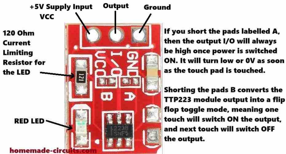
So as we can see, we have a ground supply terminal, an output terminal in the middle, and a VCC input terminal on the left side.
The VCC pinout will need a +2.5v to +5V power. The I/O output pin by default will generate a low signal or a 0V signal, until you touch the pad on the other side of the board.
As soon as you touch the pad, or bring your finger close to the pad, the I/O pinout will give you a high signal, which will equal to +5V or the voltage that's supplied on the VCC terminal.
We also see a resistor and an LED soldered on the TTP223 board. This resistor is marked as 121, which means it is a 120 ohm resistor.
The LED is a red LED which is actually quite useful as it quickly lets you know when the I/O output changes state and goes high, in response to a touch on the touch pad.
We can also see pads labelled A, B and another empty pad on the right side without any label.
These serve as additional functionality for the TTP223 module.
So I have explained how these jumper pads can be used to modify the working attributes of the module.
How to Connect A and B Pads
When you join or short the pads labelled A, then the output I/O will always be high once power is switched ON. It will turn low or 0V as soon as the touch pad is touched.
It will stay low as long as the touch pad is in contact with your finger, and will turn high once the touch is removed.
So basically it reverses the default I/O output specification of the module in the opposite direction.
Shorting the pads B converts the TTP223 module output into a flip-flop toggle mode.
Therefore, now when the module is powered and you touch the pad, the output will alternately turn ON and OFF (flip/flop) in response to subsequent touching of the touch pad.
The third jumper pads on the right side without any label can be used to reduce the touch sensitivity of the TTP223 module.
You can try connecting any ceramic capacitor below 5nF across these pads and reduce the sensitivity to some degree.
This means, now the touch pads sensitivity will reduce and will not respond if your finger is at some distance away from the pads.
Use TTP223 with a 12V Relay and 220V Loads
If you want to connect a 12V relay with a TTP223 output, you can configure a relay and the TTP223 module as shown in the following diagram. Using this setup you can easily switch any 220V load ON/OFF with a TTP223 module.
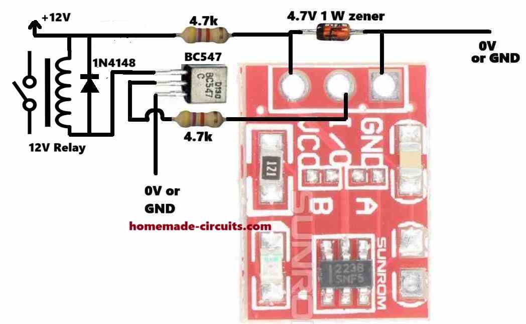
The 12V DC is reduced a 4.7V DC for powering the TTP223 module through a 4.7V zener diode and a 4.7k limiting resistor.
The I/O output is configured with a BC547 transistor which drives a relay on its collector side using the 12V DC.
If you want to use a 5V relay, then you can eliminate the upper 4.7k resistor and the 4.7V zener diode, and connect a +5V supply directly to the relay and the VCC of the TTP223 module.
Please give calculations of base resistor of 4.7k and also of power supply rail resistor of 4.7k
Transistor base resistor can be calculated as explained in the following article:
https://www.homemade-circuits.com/how-to-make-relay-driver-stage-in/
The zener diode resistor is not critical and can be any value between 1k and 4.7k. More details are given in the following article:
https://www.homemade-circuits.com/how-to-calculate-zener-diode-resistor/
Hi Swagatam, Connected a 10 K resistor to pin 3 of TTP223 and the other end of resistor to ground. Connected VCC of TTP223 to +5v and ground pin of TTP223 to ground. Momentary +5v to pin 3 of TTP223. Nothing happens. Momentary +5v to ground side of 10K resistor. Nothing happens.
Thanks Norman,
Then how do we use the pin#3 to manually toggle the IC output? If it is not working through a manual option, then how can be expect it to work through an external source?
So finally it seems it is better to go for the 4017 option.
Hi Swagatam, Ok, I set up the buffer exactly like your schematic on the bread board. The circuit powers up but times out in about 9.5 seconds. I tried two different TTP223 units. No Change. I really appreciate your efforts! I guess I will use a 4017 circuit in place of the TTP223 to achieve the toggle switch. I don’t want to keep beating a dead horse! Thanks!
Thanks Norman, what happens if you toggle the pin#3 with +5V through an push-switch manually, with a 10k resistor connected between pin#3 and ground?
It would be interesting to know what is causing the timeout?
The 4017 option could be used ultimately to solve the issue, afterwards…
I do not know how to use or make a transistor buffer. The circuit is working the same on the breadboard and PCB now. If I touch the TTP223, the circuit works correctly as originally designed. That is: 34838 output grounds pin 3 of TTP223. TTP223 is powered by 5v through a 1k resistor. TTP223 output triggers a BC 337 transistor through a 10k resistor to the transistor base. The BC337 grounds the LED from its collector to emitter. If I turn the circuit on with the IR remote transmitter, the circuit times out after 7.5 seconds. If I turn the circuit on with the IR remote transmitter and then remove the connection from the out pin of the 34838 to pin 3 through a 1m resistor, then the circuit works correctly. Therefor the 34838 is creating the problem. I tried two different IR remotes.
Ok, please try the following buffer circuit and check if it works or not: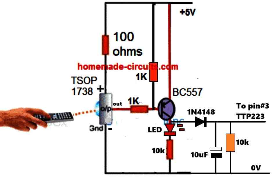
" rel="ugc">
Yes, I supply the TTP223 through a 1k resistor and supply the LED through a 1k resistor directly from the 5v supply. No change. Why would the circuit work correctly if I physically touch the TTP223 and not work correctly when it is turned on with the 34838 38khz remote control?
We have to check whether the remote control output is generating the required ON/OFF logic correctly or not, or we may have to use a transistor buffer between its output and pin#3 of TTP223.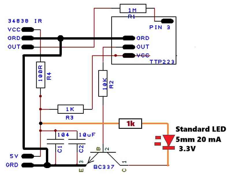
For the moment you can try replacing the flashing LED with any ordinary 3.3V 20 mA LED and check the response again, and make sure to connect all the ground lines in common as shown in the following image:
" rel="ugc">
Hi Swagatam,
I spoke too soon! The circuit works perfectly on the bread board but does not work correctly on the PCB. When I press the 38khz transmitter the circuit turns on and the flashing LED flashes through one cycle, then it turns off. I thought that maybe the electrical traces running under the touch switch might be the problem, so I reoriented the circuit to prevent any interference with the touch switch. No change. I tried touching the TTP223 and the circuit worked as planned. So, if I physically touch the TTP223, the circuit turns on and continues until I press the 38khz transmitter or touch the TTP223. So, the circuit works correctly with a physical touch of the TTP223 but turns itself off if the IR remote turns it on.????
Hi Norman,
did you implement the corrections which I had suggested in my earlier comment?
“…..the LED anode must be directly connected to the +5V supply through a 1k resistor, and not to the VCC of the TTP223.
Ans also the 1uF between the sensing input of TTP223 and ground must be removed…….”
Hi Swagatam,
I found a solution. I used my original circuit and added a 1n4148 from the output of the TTP223 to the 10K resistor at the base of the BC337 transistor which provides a ground for the self-flashing LED. Thanks!
Thanks Norman,
Glad the problem is solved now.
Hi Swagatam,
I just posted and made a mistake in saying the circuit would not turn off with the 38khz transmitter. The problem is the circuit still turns itself off when the flashing LED finishes it’s first cycle. So the changes did not help or hurt the circuit. Sorry for not being clear with my description.
Hi Swagatam,
I tried your suggestion. First I added a 10uF cap and a 0.1uF cap to the supply of the circuit. No change. I then added a 1K resistor to the supply to the TTP223. The circuit turned on but would not turn off with the 38khz transmitter. After checking the circuit, I realized I had the 1K resistor in the supply to both the 34838 and the TTP223. I fixed that and tried the circuit again. It turns on with the 38khz transmitter but will not turn off with the 38khz transmitter. It will turn off when I physically touch the TTP223. Any other suggestions? Thanks!
Hi Norman,
I saw your schematic in my email, it looks like the LED anode must be directly connected to the +5V supply through a 1k resistor, and not to the VCC of the TTP223.
Ans also the 1uF between the sensing input of TTP223 and ground must be removed.
Hi Swagatam,
I have a circuit that uses the TTP223 with a 34838 IR receiver module that simulates a touch by sending a negative signal through a 1M resistor to pin 3 of TTP223 when it receives a 38khz signal from the IR transmitter. This makes a very nice toggle switch. I have used this setup many times with success. I am using this to switch an LED on and off using a NPN transistor, which works fine when a standard LED is used. My problem is I want to use self-flashing LEDs. I switch the circuit on and the LED flashes through it’s cycle and then it turns off the TTP223. I know this should work as a remote control toggle switch. I just don’t understand why the self flashing led would trigger the TTP223 as if it were touched. Help!!!
Hi Norman,
Without checking the circuit practically it is difficult for me to suggest exactly why the self-flashing LED may be triggering the TTP223 module. One possible reason could be some kind of RF noise from the LED that may be rattling the TTP223 to get triggered. You can try adding a 1k series resistor with the TTP223 (+)supply and also capacitors across the supply +/- terminals of the IC and see if that solves the issue or not?
hi swagatam.
re your post……” Use TTP223 with a 12V Relay and 220V Loads”
https://www.homemade-circuits.com/ttp223-capacitive-touch-module-explained/
what value components would i use for 9v operation ? please
thank you, dave
Hi Dave, you just have to replace the 12V relay with a 9V relay, that’s all, nothing else needs to be changed.
normal switch which is switched on goes not direct on ..but goes on of on off until the contact comes to a solid on state .
does this item get no issues like the switch and just creates one steady pulse ..
It can be turned into an ON/OFF switch by shorting the pad B.
is there no contact dendring ..pulsating like a normal switch does from going one state to an other..i would like to know if its just ONE pulse…or more
..
Sorry, I did not understand what you meant by contact dendering?
Do you mean flip-flop? or alternate ON/OFF mode.
Hi Swagatam,
Thanks for the quick response. Your solution works perfectly. You are such a good resource for DIY electronic enthusiast. Thanks again for being there when we are struggling.
Thank you Norman, I am glad I could help you to solve the problem.
All the best to you!
Hi Swagatam,
I am now powering the referenced circuit with 5v USB. The circuit works as long as I am touching the TTP223. It appears that the one shot is not timing as expected. I have tried increasing the capacitor(smd) from 10Uf to 22Uf to 47Uf with no change. The timing resistor is 100K. It makes me think that the motor current draw is affecting the 555 one shot. I can email you a schematic if you need more information. Thanks!!
Hi Norman,
I saw the diagram which you sent to my email ID.
The problem might not be due to high current consumption by the motor, because the motor current is handled by the relay.
The problem could be due to the high voltage spikes generated by the motor.
Please connect a reverse diode across the motor wires along with a 10uF capacitor.
Additionally add a 0.1uF, and 100uF capacitors right across the IC 555 supply pins, along with a 1N4148 parallel diode.
Let me know if that helps.
Hi Swagatam,
I have a circuit that uses a TTP223 with both “A” & “B” open. The output from TTP223 triggers a BC548 that grounds a 555 one shot. The output from the 555 one shot triggers a BC548 that actuates a 5V relay. The relay NO contacts feed 5V and ground to a 5vDC motor. Everything works except the motor draws too much current for the 5v battery supply. The motor is one step up from a 130 motor. The 130 size motors really don’t seem to have enough power for my set up. The circuit draws 370ma with the motor running. I am trying to fit all of this in a small box, so that is why I am using AAA batteries. What do you think about using 3 AA batteries for 4.5v ? Space is the limiting factor. I can power it with a USB cord, but that makes it cumbersome & limited as to where you can set it up.. Lithium batteries are expensive which would make the device less attractive. Any suggestions????
Hi Norman,
AAA batteries will not last long with 370 mA current drain, also remember that the 5V relay will also draw a significant amount of current.
So, an USB supply or a Li-ion battery are the only two viable options available for you.
Hello, what is the part to the right of jumper A? What is the value of this piece? Thanks
Hi, that could be an SMD capacitor. The value is not known to me, you may have to find it using a capacitance meter.
Thank you Swagatam for the updated “How to Use TTP223 Capacitive Touch Switch Module [Pinouts Explained]” article. It has cleared up my confusion.
I bought some of these touch modules and some 5V relay modules to make some switches for toggling household lignts. The relay modules have a red LED to indicate power and a green LED to indicate they have been switched on, however I discovered that the relays I bought engage and their green LEDs illuminate when receiving a LOW signal rather than a high signal.
I tried to compensate for this by closing Jumper A on the touch module, expecting that it would send a high signal when inactive, and when touched its signal would go low and its red LED would light. In other words, I thought closing Jumper A would reverse the normal behaviour of the touch module. It doesn’t. As you have explained, closing Jumper A simply changes the default (initial power on) state to high rather than low.
With Jumper A closed I can use the relay’s NC connection to control my lights effectively, the only drawback being that the LED on the touch module will be illuminated whenever the lights are switched off..
Thanks for all you do to promote electronics knowledge and creativity around the world.
Chuck Cram, Canada
.
Thank you Chuck, Glad you liked the post.
I think the problem is related to your relay module, because the TTP223 LED will switch ON/OFF correctly as per the high/low situation of its OUT pin.
Instead of using a relay module, if you could configure a discrete 5V relay, with diode, transistor etc with the TTP223 module and use external LEDs with the OUT pin of the TTP223 that would illuminate the LED correctly as you want it to be.