In this article I have explained how to connect and use the TTP223 capacitive touch switch module. These modules work using 2.5V to 5V. They are all pre-debounced, all you need is to provide the DC supply across the VC and GND terminals, and you get an output in the middle.
So it is really that simple, you just have to give a +5V and ground, and touch the touch pad, and the output responds to your touch operations.
Main Electrical Specifications
- Operating Voltage: 2.0V to 5.5V DC
- Operating current: @VDD=3V, no load, SLRFTB=1. At low power mode typical 1.5uA, highest current usage is 3.0uA. At fast mode this is around 3.5uA and maximum current around 7.0uA@VDD=3V, no load, SLRFTB=0. At low power mode the current consumption could be around 2.0uA and a maximum of 4.0uA. While working at fast mode current intake is around 6.5uA and maximum is 13.0uA.
- Output Type: Digital (open-drain or push-pull)
- Sensitivity Adjustment: Sensitivity can be adjusted by attaching an external capacitance(0~50pF).
- Response Time: max ~ 60mS in fast mode, ~220mS at low power mode @VDD=3V
- Output Pulse Length: Specified in the datasheet
- Power Consumption: Low
- Dimensions: 15mm x 11mm
- Operating Temperature: -20 ~ +70 ℃
- Trigger Mode: Toggle or momentary
- Noise Immunity: May have noise reduction features
- Interface: VCC, GND, OUT
It Works Capacitively without Physical Touch
Actually, you don't even have to make a direct contact with the touch pad. If you put your finger pretty close to the touch pad, the output toggles ON or OFF.
That means you are able to put it behind a case, or an external cover and still switch the device ON/OFF by touching the case just above the touch pad externally, without making a physical contact with the touch pad.
TTP223 Pinout Function
Now let's take a closer look at this TTP223 capacitive touch switch module, and understand its Pinout functioning in details.
As shown below, on the flip side of the board we can see a touch pad.
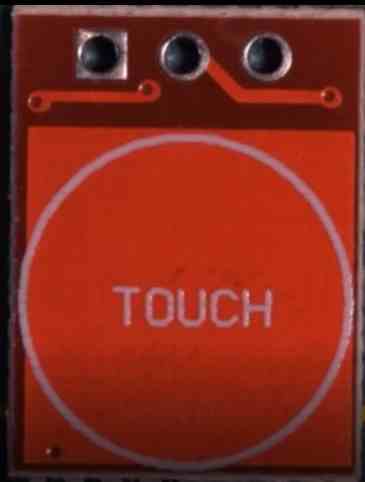
Next, as shown in the next image below, if you turn the board around, it shows the labels for the various pinouts for the relevant connections.
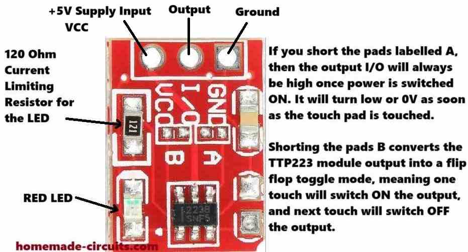
So as we can see, we have a ground supply terminal, an output terminal in the middle, and a VCC input terminal on the left side.
The VCC pinout will need a +2.5v to +5V power. The I/O output pin by default will generate a low signal or a 0V signal, until you touch the pad on the other side of the board.
As soon as you touch the pad, or bring your finger close to the pad, the I/O pinout will give you a high signal, which will equal to +5V or the voltage that's supplied on the VCC terminal.
We also see a resistor and an LED soldered on the TTP223 board. This resistor is marked as 121, which means it is a 120 ohm resistor.
The LED is a red LED which is actually quite useful as it quickly lets you know when the I/O output changes state and goes high, in response to a touch on the touch pad.
We can also see pads labelled A, B and another empty pad on the right side without any label.
These serve as additional functionality for the TTP223 module.
So I have explained how these jumper pads can be used to modify the working attributes of the module.
How to Connect A and B Pads
When you join or short the pads labelled A, then the output I/O will always be high once power is switched ON. It will turn low or 0V as soon as the touch pad is touched.
It will stay low as long as the touch pad is in contact with your finger, and will turn high once the touch is removed.
So basically it reverses the default I/O output specification of the module in the opposite direction.
Shorting the pads B converts the TTP223 module output into a flip-flop toggle mode.
Therefore, now when the module is powered and you touch the pad, the output will alternately turn ON and OFF (flip/flop) in response to subsequent touching of the touch pad.
The third jumper pads on the right side without any label can be used to reduce the touch sensitivity of the TTP223 module.
You can try connecting any ceramic capacitor below 5nF across these pads and reduce the sensitivity to some degree.
This means, now the touch pads sensitivity will reduce and will not respond if your finger is at some distance away from the pads.
Use TTP223 with a 12V Relay and 220V Loads
If you want to connect a 12V relay with a TTP223 output, you can configure a relay and the TTP223 module as shown in the following diagram. Using this setup you can easily switch any 220V load ON/OFF with a TTP223 module.
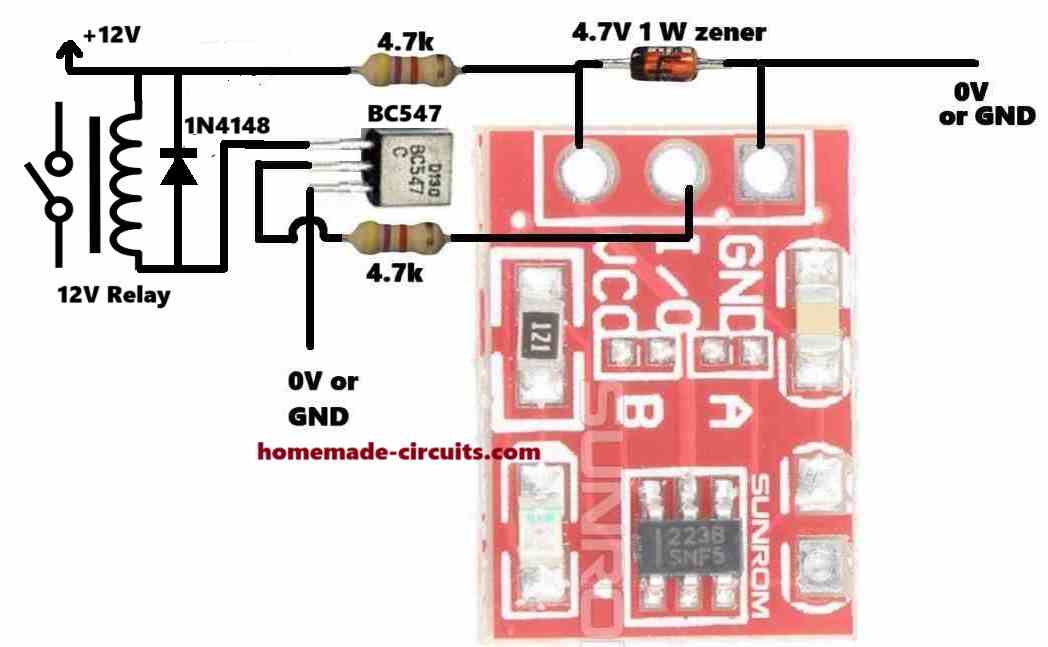
The 12V DC is reduced a 4.7V DC for powering the TTP223 module through a 4.7V zener diode and a 4.7k limiting resistor.
The I/O output is configured with a BC547 transistor which drives a relay on its collector side using the 12V DC.
If you want to use a 5V relay, then you can eliminate the upper 4.7k resistor and the 4.7V zener diode, and connect a +5V supply directly to the relay and the VCC of the TTP223 module.