

A tuned radio frequency receiver (or TRF receiver) is a form of radio receiver which is made using a number of tuned radio frequency (RF) amplifier stages accompanied by a detector (demodulator) circuit to draw out the audio signal, along with an audio frequency amplifier for amplifying the extracted audio into a loudspeaker.
This kind of receiver used to be a lot popular during the 1920s.

You will find two fundamental types of radio receiver circuits that people can easily construct. The most straightforward of the two is the receiver that does not require any external power and extracts the RF signals directly from the atmophere and transforms it to sound signal through a single, easy diode rectification step. This form of well-known passive receiver best remembered as the crystal set or diode radio.
Nearly all basic crystal radios experience difficulty in selectivity and audio output. In order to strengthen both these attributes, the captured RF level has to be boosted before amplification. The remedy is to boost the performance of the antenna by putting it to a greater height over the ground and so that it is much longer length wise, or simply to transfer the receiver nearer to the RF signal source.
Typically none of the two solution is looks very practical. However when we choose to proceed the active way by creating a receiver almost anything that you can do to the signal transmission electronically turns into a fair game.
The RF could be amplified prior to detection step, or changed into a new frequency (IF) to be amplified again prior to detection. In reality a number of well-known communication radio receivers switch the RF 3 times prior to the modulation data is transformed into sound frequency and directed further for audio frequency (AF), amplification. All the three of the discussed tuned radio frequency receiver circuits can be classified ideally to be in the active class.
Tunable/Amplified Receiver

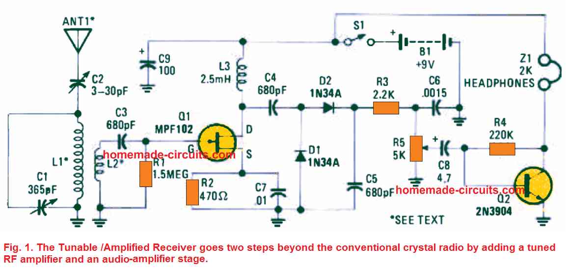
The first discussed TRF receiver circuit (see Fig. 1) moves a couple of steps over and above the standard crystal radio with the addition of a tuned RF amplifier stage before the signal is demodulated and an audio amplifier stage after the demodulation stage. The RF power through the antenna is applied by using a tiny trimmer capacitor, C2, to the tuned circuit consisting of L1 and C1.
The specified transmitted signal is selected through C1 (a 365 pF GANG capacitor). Inductor L2 delivers the tuned RF signal towards the RF amplifier input, which includes Q1 which is an MPF102 N-channel, junction field-effect transistor or JFET.
These transistors amplify the RF signal numerous times prior to transferring it onto the detector stage. A couple of 1N34A germanium diodes (D1 and D2) are hooked up within a voltage doubler/detector circuit which contributes an increased output signal to drive the audio amplifier circuit.
The RF component of the transmission, following detection, is filtered through the components C5, R3, and C6 leaving behind the audio component of the signal towards the input of the volume control, R5. A 2N3904 NPN transistor, configured like a common-emitter circuit, boosts the AF signal to a degree high enough to drive your pair of headphones or, if the signal is powerful from the local stations, a speaker is driven nicely with the help of an impedance-matching transformer.
You could receive a number of stations as soon as an 18-inch clip lead is hooked up to the antenna port. It may be possible catch six local stations when a 20 -foot length of connecting wire is used clinging through your house ceiling. The TRF receiver can be nicely operated through just one 9 volt transistor radio PP3 battery.
Because the current usage is just a couple of milliamperes, the battery must go on for many months when the unit is used normally.
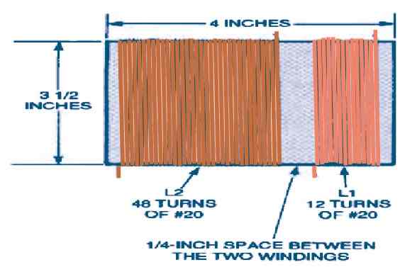
Inductors L1 and L2 can be made by winding 20 SWG enamel copper wire over a 2.5 inch long and 4 inch diameter plastic pipe.

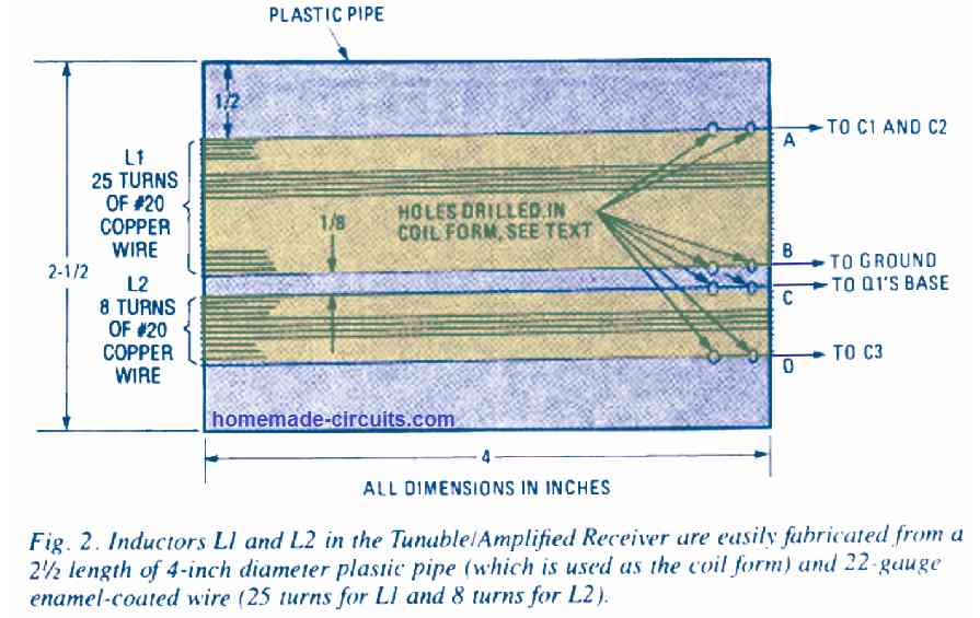
Figure 2 shows the way the a pair of inductors should be wound. Beginning with the 2.5 inch length of plastic pipe, leave around a half inch on the upper section of the coil former and punch a couple of tiny holes through the former in order to tie the start end of L1. Interlace the wire end via the two holes to create a 6-inch pigtail for attaching to C1. Wind the coil tightly, just as we do to wind solenoids, use 25 number of turns to complete L1 inductor.
After this temporarily put an adhesive tape over the the loose end of the winding, make 2 additional small holes on the former, and twine the wire from the holes to clamp the finished coil in position.
Furthermore spare around 6 inches of wire at the L1's finished end in order to enable the connections to C1 and circuit ground. Leave about an 1/8 inch from L1 end and drill a couple of more holes on the former intended for securing the start end of L2. Keeping a 6 inch pigtail, tightly wind an overall of 8 turns, within the exact same direction as L1.
Punch two more holes on the former and secure by tieing up the ground end of L2 as done in the previous steps, leaving a 6 inch pigtail for connecting to circuit ground.
Because we have just one stage of RF gain, the wiring arrangement isn't very important and any appropriate set up might work. Regardless of this, make sure to keep all the legs of the components as small as possible and put the 2.5 mH choke (L3) a little distance away from L1 and L2. If you want to use a speaker, you can hook up the primary of any small audio output transformer in place where the phones are connected and attach the speaker to the secondary side of the transformer.
To start using the radio, power it up with a 9 volt battery. Adjust the tuning of the gang capacitor C1 to different locations, until you finally begin hearing a couple of local stations loud and clear. Furthermore try connecting a 10 to 20 foot long flexible wire to C2 which will allow you to catch many additional radio stations on your TRF radio set. Adjust C2 in order to get the finest selectivity among the available radio stations.
Reflex Receiver

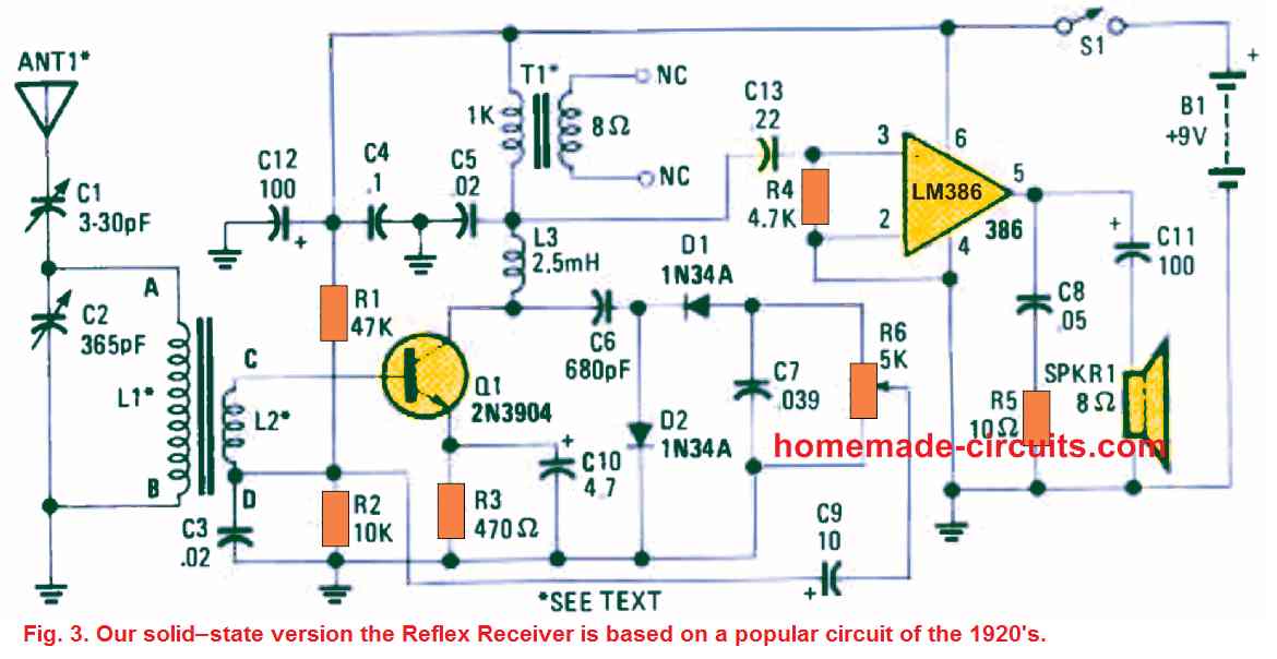
Our next TRF receiver's design, is depicted in the Fig. 3, and it is designed using the radio reflex circuit which used to be very popular during the 1920's. In those days radio was merely seeing the trend and home built radio sets were being developed with tremendous enthusiasm by the experimenters.
Now take a look at how our present day solid-state transistorized version of the reflex receiver functions. The RF signal is transferred through the antenna by means of C1 which reaches the tuned circuit consisting of L1 and C2.
One particular end of L2 supplies the RF signal to the transistor Q1 base so that the signal can be amplified, while the other end of L2 connects to the R1 and R2 junction to enable the biasing supply for the transistor. The capacitor, C3, clamps the "D" end of L2 at RF ground.
Next, the amplified RF signal is fed via C6 to a two-diode doubler + detector circuit and then the signal is further sent to the the volume control stage using pot R6.
The central slider arm of the pot R6 connects with the detected audio signal via C9 to the R1, R2 junction and the "D" end of L2. The "D" end of L2 is held at the RF ground, which is not the AF ground. This allows the AF signal to move by means of L2 towards the Q1 base for amplification. The connection between the 2.5 mH choke and T1 is held at RF ground via the capacitor C5.
The amplified radio audio available from this stage is passed to the input of the LM386 IC audio amplifier, U1, for operating a 4 inch diameter 8 ohm loud speaker. The single transistor perdorms a double function, it amplifies the RF and AM radio signals both together simulataneously.
The construction format which had been used for building our first receiver can be also applied here for building this reflex radio receiver circuit.
Inductors L1 and L2 are identical to those employed in the previous circuit and could be built by looking at the constructional details given in Fig. 2. When correctly put together, the reflex circuit will work exceptionally well even better than the first receiver by providing enhanced sensitivity and louder audio output.
Regenerative Receiver

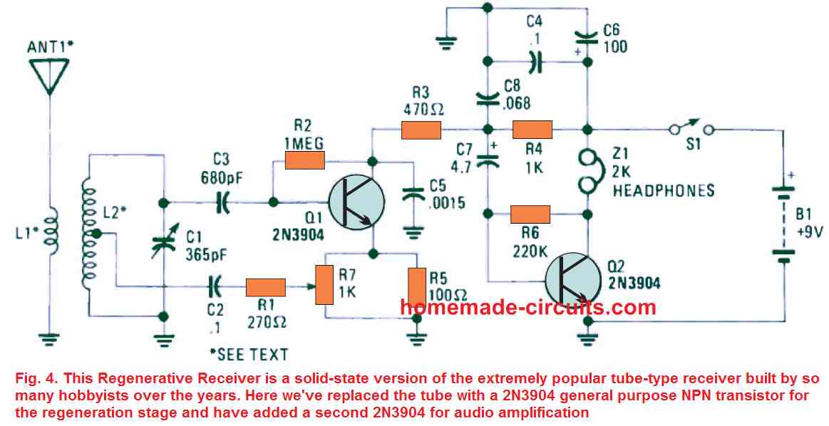
Our 3rd tuned radio frequency receiver circuit as shown in the Fig. 4 is a solid state version of the very famous old regenerative receiver which could have been built by numerous small radio makers through the years.
The main active part of the regenerative tuned radio frequency receiver circuits is the transistor 2N3904 configured for the regeneration stage, while the second 2N3904 is wired for the audio amplification. In the diagram we can see that transistor Q1 is hooked up like a customized Hartley regenerative detector circuit having the RF feedback level determined by R7, which is a 1k potentiometer.
The RF is connected via L2 to L1 and tuned to the preferred frequency through the capacitor C1.
Using BF245 FET

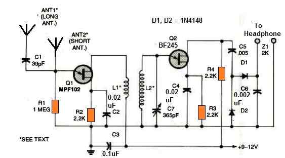
In order to enhance sensitivity for usage in a poor signal location, the above design connects a wideband RF booster amplifier to the radio receiver section. All RF signals are amplified by BF245 JFET Q1 before being sent through L1 and L2 to the customized RF amplifier (constructed around Q2). The frequency is selected using inductor L2 and capacitor C7.
The dual-diode-detector circuit, which is made up of D1 and D2, transforms the amplified output signal of Q2 into audio signal.
Inductors L1 and L2 are homemade air core coils constructed over a plastic former in accordance with the instructions provided below.

To avoid parasitic oscillations, it's critical to keep all connecting leads between the parts as short as possible. This is important because this design is a high gain radio receiver design.