In this article I have explained how to control a two pipe submersible pump valve to ensure that the pipe bringing in the municipal water is always given the main preference to the bore-well water source. The circuit is also equipped with a tank overflow cut-off feature. The idea was requested by Mr. Prashant.
Circuit Objectives and Requirements
I am big fan of your blog. I like your logic and circuit. Basically I am Soft eng but my hobby is electronic. I always read your blog and make circuit. I am happy to tell you that I have done semi-automatic water flow controller circuit from your blog and it is working from last 5 to 6 months. It saved lot of water and electricity. Thank you.
First I will brief my setup and requirement.
I have 2 pipe attached to water pump suction input point and I operate it by manually. 1st pipe is for corporation water (drinking water come daily at 5pm) and 2nd one is attached to underground water tank. So if I switch on 1st valve overhead tank will be filled by corporation water and if 2nd valve is switch on then overhead tank filled by water from underground tank.
Now my requirement is
1) Whenever corporation water come OR sense water flow in 1st pipe, water pump should start automatically and also stop suction from underground water tank so that only corporation water will be filled in overhead tank. (Just thought, can we use solenoid valve to stop water to be pulled from underground tank)
2) Stop water-pump when overhead tank is full.
3) Also I manually operate valve and store corporation drinking water in underground tank. Can we stop water pump when underwater tank is full.
The Design
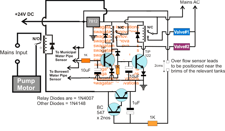
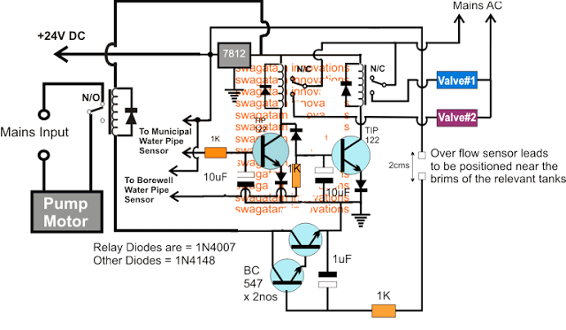
The requested idea of automatically controlling a two valve submersible pump water supply can be implemented with the following schematic

The idea is quite simple, the two relays control the two valves individually whenever the associated transistor drivers are triggered through the relevant water supply sources.
The upper left transistor's base sensor points are supposed to be attached with the municipal water pipe and this transistor relay stage becomes the preferred controller of the water supply to the overhead tank.
Anytime while the municipal water supply is active, this transistor relay stays activated, making sure that the valve#2 is opened and the municipal water is allowed to fill the overhead tank.
As long as the municipal water supply is present, the upper right side transistor relay stage is rendered inactive by the grounding of its base through the left transistor's collector.
In an event when the municipal water supply is absent, and the borewell water is present, the upper right transistor relay stage becomes active and switches ON the valve#1 enabling the pump to suck the borewell water into the associated tank.
During this time if suppose the municipal water is released, as explained earlier, the valve#1 relay is instantly deactivated by the valve#2 relay transistor, allowing the municipal water to enter the overhead tank instead of the borewell water.
The two BC547 transistors arranged in Darlington pair are used for sensing the over flow situation of the relevant tanks, whether it's the overhead tank or the underground tank, the BC547 pair instantly switches ON and grounds the base signals of the relay driver transistors, disabling the relays and the attached valves, so that the pump motor is switched OFF, and the tanks are prevented from overflowing.
The sensors could be constructed using a pair of brass rods appropriately tinned with solder and cleaned with sand paper and acetone. The distance between the sensor leads should not be more than 2cms, and should be nicely clamped over a non-conductive base
The sensors can be seen applied separately with a 24V positive to ensure an effective conduction of current across the sensor leads even in the presence of flowing water.
