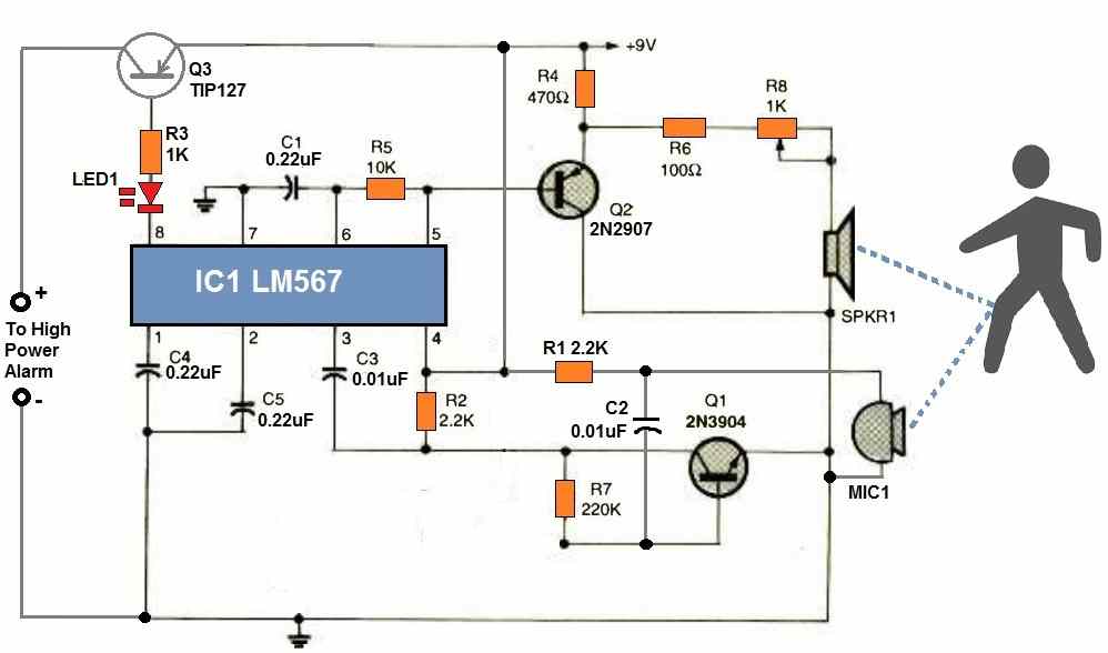
An ultrasonic burglar alarm circuit is an electronic device which transmits ultrasonic waves to detect the movement of an intruding person. The ultrasonic waves hit the intruder and the reflected waves are picked up by the circuit. This reflected wave is used to activate a loud alarm which alerts the owner about the presence of an intruder or a potential burglar.
In our ultrasonic burglar alarm circuit, the versatile LM567 phase-locked loop IC is used.
The main technical specifications of the IC are given below.
- Supply Voltage Range 3.5 V to 8.5 V
- Input Voltage Range 20 mV RMS to VCC (+0.5)
- Input Frequency 1 Hz to 500 kHz
- Output Current Max. 15 mA
For more information about the IC you can refer to the following post:
In our present ultrasonic burglar alarm design, the IC LM567 implements two functions together.
It works like a tone-decoder circuit that switches ON the output in response to a specific tone frequency linked with the LM567 at pin#3.
Additionally, the LM567 functions as a tone transmitter, producing the exact frequency tone from pin#5 that the receiver stage is intended to receive and detect.
Meaning, the pin#5 generates a tone with a specific frequency, and when this same frequency is supplied back to its pin#3, then the IC switches ON its output pin#8. If any other frequency is detected at pin#3 the IC does not respond and its output remains inactive.
Therefore, it implies that the frequency set to be generated from pin#5 must be exactly detected at pin#3 for the output to become active. If pin#5 and pin#3 frequencies don't match then the output will never switch ON.
The sensor stage of the circuit could be built with just a couple of external transistors and a few other parts. The transmitter section of the circuit uses the piezo speaker to transmit a high frequency audio signal.
The reflected tone signal is detected by the receiver's pickup, which is an electret microphone device, and is then sent to transistor Q1 for amplification. The signal is then transferred to the input of the LM567 after being amplified.
As depicted in the diagram, the piezo speaker and microphone units are placed 3 to 6 inches apart, facing towards the target which can be a possible intruder.
The circuit switches ON the output alarm device whenever something is moved in front of the microphone and speaker which reflects enough of the signal back to the microphone. The circuit may be configured to detect items from a few inches to over a meter away.
Circuit Description

Referring to the above ultrasonic burglar alarm circuit diagram, we can understand the working of the circuit with the following explanation
C1 and R5 determine the internal oscillator frequency of the LM567. It doesn't matter what the operating frequency range is as long as it is between 14 and 20 kHz.
The electret microphone's sensitivity will be diminished and its operational range will deteriorate if the frequency is set too high. The circuit can operate at much lower frequencies if you don't mind hearing to the continuously emitted high-frequency sound.
At pin#5, the internal oscillator of the LM567 generates a squarewave output. Q2 operates as an emitter follower to isolate this signal from the LM567 and feeds it to the piezo speaker.
R8 controls the output volume of the speaker. The common-emitter amplifier transistor Q1 is used to boost the reflected tone signal to a magnitude at which LM567's input circuitry can detect and latch on.
How to Setup
Setting up and adjusting the circuit is simple.
- Choose the desired type and size of anything you wish to detect and place it directly in front of the speaker and microphone, until the output alarm starts sounding.
- Now adjust R8 to tweak the range of the detection. The range of operation is primarily determined by the type of item chosen as a reflector. For example any object with a flat surface will be detected better than objects having cylindrical surface.
This circuit is great for electronics hobbyists and researchers. By substituting R5 with a 20 Kohm potentiometer, the operating frequency could be adjusted. C1's value could also be altered. Smaller values of either component might reduce the operating frequency, whereas larger ones will help to increase it.
Calculating the Operational Frequency
As explained in the previous, the ideal frequency for transmission and detection can be at around 14 kHz. This frequency is determined by C1 and R5.
The formula for calculating this frequency is as given below:
fo = 1 / (1.1 × R1 × C1)
Here, R1 should be in Ohms, and C1 should be Farads. The frequency will then be in Hertz.
Parts List
- RESISTORS
- (All resistors are 1/4 -watt, 5% units unless otherwise noted.)
- R1, R2 - 2.2K
- R3 - 1K
- R1 - 470 ohm
- R5 - 10K
- R6 - 100 ohm
- R7 - 220K
- R8 - 1K potentiometer
- CAPACITORS
- C1 - 0.22 uF, ceramic disc
- C2, C3 - 0.01 uF, ceramic disc
- C4, C5 - 0.22 uF ceramic disc
- SEMICONDUCTORS
- IC1 - LM567 tone -decoder, integrated circuit
- Q1 - 2N3904 NPN silicon transistor
- Q2 - 2N2907 PNP silicon transistor
- Q3 - TIP127 PNP Darlington Transistor
- LED1 - Light-emitting diode, any type or color
- Miscellaneous
- Piezo Buzzer
- Electret MIC