The article provides a detailed explanation regarding the various voltage regulator wiring configurations used in motorcycles. The article was submitted by Mr. Abu-Hafss.
Technical Specifications
After working on different voltage regulators, I feel to share my findings on your blog so that other people may also get benefit. Please insert the diagrams appropriately in the article. I will update further by providing examples of each type.
Thanks and regards
Abu-Hafss
UNDERSTANDING WIRING OF MOTORCYCLE VOLTAGE REGULATORS
Motorcycles are usually equipped with permanent magnet AC generators. The magnitude of the voltage produced by these generators depends upon the RPM of the engine. Despite these generators are specifically designed to produce about 13-15VAC at high RPMs, they do require a voltage regulator to provide a safe voltage for battery charging and for the electrical system. These generators could have single-phase or a three-phase winding. No matter the winding is single-phase or three-phase; all voltage regulator units have two parts i.e. Rectifier Section and Voltage Regulator Section. Here, we will only discuss various types of voltage regulators and not their internal circuits.
VOLTAGE REGULATORS FOR SINGLE-PHASE GENERATORS

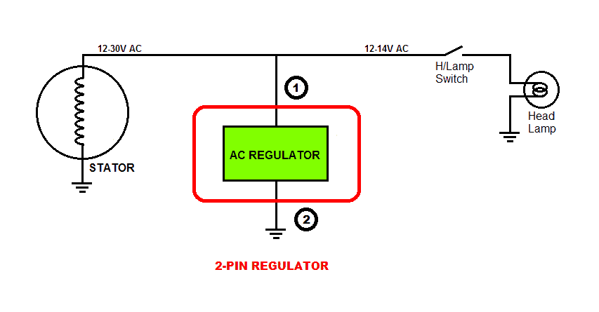
1) 2-pin Regulator: This type may be found on some small bicycles which do not have battery and only have Head Lamp & Tail Lamp. Since the incandescent bulbs work well on AC voltage, there is no rectifier section in this type of regulator. The circuit inside the unit regulates the AC voltage coming from the generator to 13.5 – 14 VAC for the bulbs. This regulator is basically an AC voltage regulator.
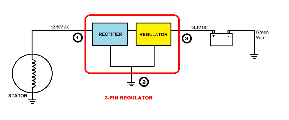
2) 3-pin Regulator: This type may be found on some motorcycles. In this system, we see that one end of the winding is grounded to the chassis of the bike, which is connected to the negative terminal of the battery. The other end of the winding supplies AC voltage to the rectifier section which converts it to DC voltage. Then it enters the Regulator section which maintains the output to an ideal 14.4V for charging a 12V battery (or 7.2V for a 6V battery) and powering the electrical system.
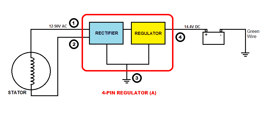
3) 4-pin Regulator (A): This type may be found on some motorcycles. In this system, both the ends of the winding go to the Rectifier section which converts AC to DC voltage and then the Regulator section regulates to 14.4V as discussed above.
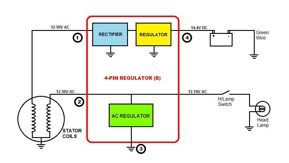
4) 4-pin Regulator (B): This is the most common type found on motorcycles with single-phase winding. In this system, the stator has dual windings. One supplies power for charging the battery and for the electrical system. The other supplies power exclusively for the Head Lamps and the Tail Lamps. This type of regulator unit is basically a combination of 3-pin Regulator and 2-pin Regulator. The 3-pin Regulator section provides 14.4V DC for the battery and the 2-pn Regulator provides 13.5 – 14V AC for the Lamps.
VOLTAGE REGULATORS FOR THREE-PHASE GENERATORS
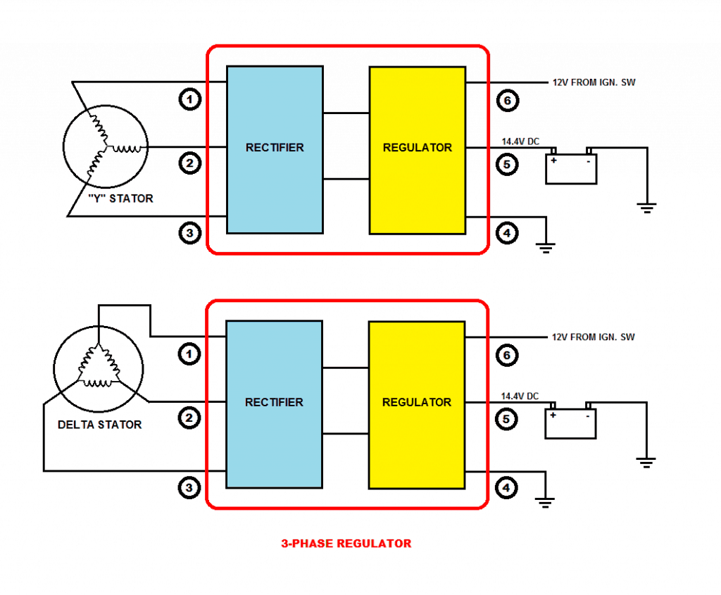
Three-phase windings are two types i.e. Y-type and Delta type.
The working principle of a regulator for three-phase generator is the same as 4-pin Regulator (A), but of course, the internal circuitry would be quite different.
An example of such 3-phase regulator can be seen in the article: motorcycle shunt regulator circuit using SCR
.
I have a 1980 Honda C70 motorcycle which has a 6 v system. It has a small component rectifier and does not have a voltage regulator. Recently, the system blew all the bulbs out. Put a new battery in and is measuring a bit over 6v at idle Ann up to 7.4v at higher rpm’s. Any advice as to what the issue might be would be greatly appreciated.
Thank you
It could have happened due to a sudden voltage spike from the alternator. You can add the following simple regulator with your rectifier output, and protect all the electrical equipment: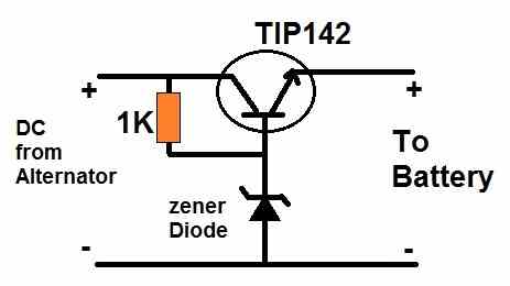
" rel="ugc">
My motorcycles use voltage regulators for three-phase generators. I installed LED headlights for it, but when they got on the station, the lights flashed. Can you help me
Please explain the issue elaborately.
In short, the regulator short-circuits the generator coil?
That’s how shunting regulators work.
Hello, just want to know please can you help me? I have a generator with two wires (yellow, black red) and a 2-pin regulator. As far as I know, yellow is responsible for lighting. Can I connect the yellow wire directly to the head light switch? Or should I connect the yellow wire to the regulator and then to the head light switch?
Hi, If you are sure about the yellow then you can connect it with the headlight. If the alternator max voltage is much higher than the headlight specifications, then you may have to use a regulator in the middle.
Thank you! Is it possible to do this, connect the yellow wire to the input of the head light switch and connect the outgoing red wire to the regulator and other consumers?
I am not sure about the headlight switch configuration, so cannot suggest regarding this. If you can tell me the switch wiring details then I maybe i can comment.
hello..can you make a regulator diagram for headlight
Hi, please provide the specifications of your headlight, I will try to solve it for you…
12v 35w
You can try this circuit: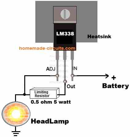
" rel="ugc">
Thankyou sir..success always for you
Thank you Roby, You are most welcome!
Currently working on an antique motorcycle( Yamaha DT 400) and a working voltage regulator circuit is all that’s standing in the way of the project being finished. It’s 6v with only a rectifier on the charging side and AC on the headlight circuit. Both put out 18v Thanks for this content. This content helps guys like me. Only thing left is to find the right parts as this bike came with no regulators from the factory.
Thank you for your kind feedback. Appreciate it very much. Glad you found the post helpful.
I have installed an unnamed cc110 engine, made in China, the challenge is to burn the lights, its rectifier is 4pin and I also don’t use a battery. What should I do so that the lights don’t burn.
You will need to install a voltage controller circuit so that your lights do not burn due to high voltage from the alternator.
I have another proplems, within 2 weeks I used 4 plugs and 2 cdi 5pins also are failed my engine is 110cc engine starter.I kick until my legs get tired but the motorcycle does not start. I don’t know what the problem is exactly
I think you must take the help of a qualified automobile mechanic, only he will be able to solve your problem.
Can you please tell me which wires would run to what on a 8 wire regulator rectifier? Thanks.
Sorry, I have no idea about an 8 wire regulator unit.
Hi, is there a way to find out which 4-pin regulator (A or B) I have using a multimeter? Thanks
Hi, you can the output voltage with a multimeter but the input will need to be fed with a 12V AC source.
hi there,just wanna know please if you could help me out,outboard 3 phase regulator rectifier for a suzuki DF50..how to connect the rectifier to my stator,no harness plug,could i connect the 3 phase side as i want to or there is a sequence to it?
The three inputs of the rectifier does not have any polarity, you can connect any way round with your motorcycle’s 3 phase AC source.
How can an overvoltage protection circuit (capacitor and relay with warning light) be added to this type of circuit for single phase PM stator at 32A 12V?
You can use the following type of shunt regulator for a constant output voltage: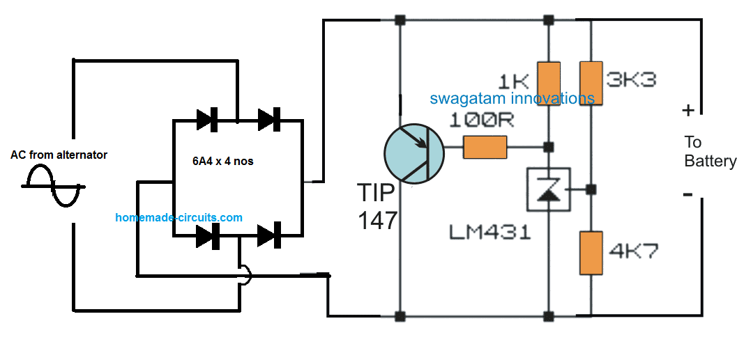
" rel="ugc">
The 3k3 and 4k7 resistors can be tweaked for fixing the desired output voltage.
Good Morning
1981 dt175 with cdi magneto .
Need a circuit diagram to built a voltage regulator for this bike.
output voltage is 6v
Hi, you can try the second last circuit from the following article:
https://www.homemade-circuits.com/motorcycle-full-wave-shunt-regulator/
I converted a 6v electrical system of my father’s 1997 Honda xl125s to 12v. I used a 8 poles (1 for primary, 7 poles for ac) which is producing 60 acv tops around 6000 rpm. I used a 12v regulator/rectifier for converting the fluctuating ac from stator to dcv which is wired directly to my 12v gel battery. This regulator comes in 5 wires (yellow:pink for ac, red:green for dc output, black for the variable dc voltage measurement connected to the black wire which is routed to ignition switch). Stator ground is floating. Full wave.
Using a multimeter, I test the charging leads attached to the battery terminals and it reads 14.4v, as soon as I test the leads dismounted from the battery using multimeter, the dcv reading is only 2-3 dcv.
I also have a Honda XL, although mine is an XL250S. I observed a similar thing when fitting a 12V regulator/rectifier to my old 6V circuit. The stator open circuit voltage measures 50-60VAC and with the reg/rec fitted, the reg/rec open circuit DC output measures only 4 – 5 VDC. I have several 12V reg/rec and have swapped the units to see if they are faulty, but each gives a similar result. This leaves me quite perplexed! Can anybody clarify why this is the case?
I am wondering if there is a way to rectify and transform the output of a motorcycle lighting coil rated at nominal 6V AC to provide enough voltage to charge a 12V battery.
I have an off-road motorcycle that was produced with a headlight and tail light. The lighting coil serves only those two bulbs with 6V AC. I am adding LED turn signals, an LED brake light, and horn, all rated at 12V, to make the motorcycle road legal. My intention is to power those items from a 12V battery and I would like it to charge while the engine is running.
This site is an amazing wealth of knowledge and I appreciate the clear explanations and generous assistance from all the authors.
Thank you, and I am glad you liked this site.
To increase a 6V supply to 12V you will require a boost converter circuit. You can try the following circuit for boosting 6V to 12V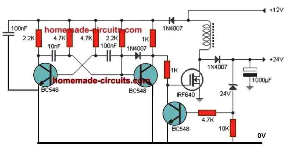
" rel="ugc">
The circuit was designed for boosting 12V to 24V but you can use it for your purpose also by replacing the zener diode with a 12V zener diode.
Hi Swagatam,
I have acquired a late ’80’s Yamaha 2 stroke 125cc future classic in a few pieces and the wiring loom and all seem components to be intact except for the combined regulator/rectifier unit where the input connector has been cut off(the output side of the regulator/rectifier unit is intact). The bike uses a delta stator and sadly all 3 input wires are the same colour, thus my primary question is whether each input wire must uniquely match a stator(or at least its output on the wiring loom) or if they can be randomly connected?
Robert
Hi Robert, since the output from the alternator would be AC, the wires do not need to have polarities, they can be randomly connected to a regulator unit.
on my 72 Suzuki TS185 which had 6 volt ckt but changed now to 12 volt full wave 4 wire, RR after lifting the ground off the charge coil. it is working well producing a regulated voltage. In place of the 6V flood wet cell battery , I have put in a 10 cell Nicad pack, which does get charged but I wonder about providing a proper charge current. how can I regulate the current going to the battery?
You can simply do it by adding a suitably calculated resistor in series with the positive line, as explained in the second concept under this post:
https://www.homemade-circuits.com/simple-ni-cd-battery-charger-circuit/
Hello, I am working on an 80’s scooter that has precisely the setup you describe in item no. 4 (4pin regulator B) I intend to provide rectified and filtered current to the lighting circuit in order to use led headlights. I was told a 4diode full wave rectifier and a capacitor to act as a stabilizer was the simplest (and cheapest) way to go. Am I on the right track? can you provide me with specs for the items to buy? thank you so much.
Hello, using a single diode is probably the cheapest way of making an automobile rectifier. However for improved performance and charging you can use a bridge rectifier configuration for the regulator.
You can construct it using 4 numbers of 6A4 diodes. Although the filter capacitor is never needed for charging a battery through this type of regulator, you can use one rated at 1000uF/50V
Sorry – that was a ’78 Kawi Twin, not an ’83 – I am working on two bikes at once.
I think the year is important, because the generator/R/R changed in ’79 on this series.
Thanks again,
Frank
Swagatam:
Thank you very much for your explanation of the R/R circuits. I have an old ’83 Kawasaki KZ750 Twin, and some poorly routed wiring shorted (smoked badly), burning most of the insulation on both the positive and negative connections to the (1 Phase) R/R, and shorting out the R/R, as well.
My question is this: I have on hand a newer 3-phase type R/R that fits barely – I am wondering whether I can just connect the 2 yellow wires from the generator (aside from the obvious ground and +12 output) to 2 of the three yellow wire inputs to the R/R, and have it yield the right voltage and work? I’m guessing it is like dropping one of the 3-phase stator coils, and might still work OK… am I on the wrong track?
Again, thank you so much for your site.
You are welcome Fastfrank. According to me your assumptions are perfectly correct, and you can connect the two AC inputs from the generator to any of the two yellow wires of the Rectifier/Regulator. This should yield a 12V full wave rectified DC across the RED/BLACK wires of the R/R
Working with a small engine. The flywheel is Kohler 1702530S. The “stator” (Kohler 1708509s) has two coils, but they are wired together with only 1 output wire. This output is AC. At about 6000 RPM, thru a diode, it might put out 17Volts RMS. I want to use a rectifier/regulator but the three pin ones I see want two AC inputs. Since the coils are grounded to the engine block, can I run a ground wire to the 2nd AC input pin? Would there be issues if both the AC and DC sides of the circuit are using the same ground?
A 3 pin regulator probably also uses a single diode rectifier, with one wire connected to the diode input (anode), second wire to the diode output (cathode) and the 3rd wire is meant to be connected with the common ground. This common ground is common to both the input and the output of the regulator, so according to me you can use the ground as the common line for both input and output, for a 3 pin regulator.
Hi,
I wonder if you can help me.
I have a 1970s Suzuki A50P and it has a 6 volt system. I am going to need to do some extensive rewiring and thought I could possibly improve the charging system. This bike has no regulator but does have a simple diode rectifier for the battery charging system which I believe to be quite poor where the battery either gets over charged or if the indicators and brakes are used to a reasonable extent the battery goes flat. I believe the headlight and tail light run AC from the charging system. I have seen various 6V regulator / rectifiers available usually with 4 wires and I was wondering if I could use one and how I would wire it up. I plan to use LED bulbs to reduce the draw on the system but these will not work correctly on the A/C headlight and tail lights. Any clues on how to wire this would be greatly appreciated. Regards Lee
Hi, please provide the color details of the wires from the regulator that you have? It will try to figure it out!
Hi, Ok I can tell you that the charging system has a stator plate with 3 coils mounted on it. One of the coils is used to power the ignition system. After that things get a little hazy, I have 6 wires coming out from the stator plate but I can’t really trace where each of them connect to internally as most of them must be soldered in a very tight area. It’s a shame I can’t attach a copy of the wiring diagram it might have helped you. Here goes on the explanation: I have a yellow wire, a green wire, a blue wire a black wire, a yellow with a white tracer wire and a very short blue wire with a fork type connector on it. The wiring diagram I have from a workshop manual shows only two coils (probably for simplification) and one of these is for the ignition system that I don’t intend to modify in any way. The coil in the diagram is shown attached at one end to earth, then just a few coils up is the green wire take off, then close to the end of the coil is the yellow with white tracer take off and right at the end of the coil is the yellow wire take off. The black wire is for the ignition The blue wire with the fork isn’t shown on the diagram but I assume it must be an earth connection and the other blue wire isn’t shown on the diagram either. The diagram indicates that the yellow with white tracer isn’t used. The yellow is a feed to the headlights (A/C) through a switch and the green connects to the diode rectifier when the headlights are not on and the yellow and green connect together when the headlights are on. Hope this helps. Regards Lee
OK, I thought it is a 4 wire rectifier regulator, but six wire can be difficult to figure out.
It seems it may be a standard alternator regulator circuit, where the regulator controls the field coil of the alternator for controlling the output voltage t the battery.
I have one related article, which perhaps you can compare with your wiring design and see if it helps you to identify the connections, or you can build a prototype design for verifying the operations practically.
https://www.homemade-circuits.com/car-alternator-regulator-circuit/
Hi Thank you very much for your help but this all looks way too complicated for me. I suspect that if I connect the green wire to the yellow wire and connect this to the aftermarket 6v regulator / rectifier as the AC in then connect the other AC in to earth. The DC out – also goes to earth and the DC out + goes to the battery. Then wire all the electrics from the battery instead of having an AC supply for the headlights it might just work. Thanks again Lee
Hi, yes it is a bit complex for any newcomer. I hope your assumed idea works! Wish you all the best!
I have an antique car very similar wired to the 3 pin regulator except I use a single diode to convert a magneto output to DC then through a auto tail light bulb to drop the current then to charge a small battery for LED headlights. The original car used magneto lights and unless the car was going as fast as possible, the headlights were useless. There is no voltage regulation. The magneto is the power source for the cars ignition system and coils which produce 200V emf at times instantly frying the LED headlights. Will a 3 pin regulator work to stop the excess voltage?
First of all you must rectify the low voltage AC using a bridge rectifier and not a single diode! This will instantly double the power to the headlights. I am assuming this voltage is below 24 V maximum, in that case you can use a shunt type regulator as described in the below given post:
https://www.homemade-circuits.com/motorcycle-full-wave-shunt-regulator/
3 pin regulator can be also used, such as using LM196 IC or the designs shown below:
Voltage Regulator Circuits using Transistor and Zener Diode
The magneto can put out 30VAC as measured with a meter. The car would show an occasional spike of near 200V as indicated by an o-scope due to coil sand points operating. The magneto AC frequency is variable between about 50 Hz, 12VAC to about 200 Hz, 30VAC depending upon the engine speed. This was measured with a meter, so I’m sure peak voltage is higher. The half wave rectifier delivers enough current to keep the small battery charged allowing a stop light and occasionally head and tail lights. The LED headlight bulbs have a 30V max rating and the occasional high emf burns out the LED electronics instantly. Recently I’ve tried a TVS diode 600W and a clamping voltage of 27. Limited testing and the LED headlights have not burned out, but my knowledge of TVS diodes is but trial and error
Here’s an easier circuit to regulate your alternator output:
" rel="ugc">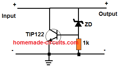
The above circuit will work for 30 V or any other volt depending on the transistor specifications. You can try a TIP35C for the transistor which can handle up to bursts of 25 amp @ up to 100V.
The zener diode value will determine the output regulated voltage value.
This circuit will be more reliable and robust than other alternative
Hi, I have a 1974 rd 350 Yamaha two stroke, it’s very modified,I have a lithium battery and a motogadget m unit,both of these cannot be over charged,I also run a vape ignition with a built rectifire to charge the battery. The vape ignition can run with out the battery, I have a red wire that comes from the cdi unit to charge the battery but at high rpm it send out a charge higher than 15 volts,can I add another rectifire to reduce this to 14 volts safely? Thanks for your time with this issue. Nick
Hi, if the maximum voltage is 15V then you can bring down to 14V by adding a couple of 6A4 diodes in series with the poritive line. Otherwise a simple shunt type crowbar should be enough for the job
 " alt="motorcycle battery charger" />
You can remove the op amp pin7 resistor and zener, and connect pin7 directly wit the supply line.
Adjust the preset until the output stabilizes to 14V exact.
Could you contact me concerning an EFI project I’m working on. I’ve developed an aftermarket EFI system for ’06-’17 KTM/Husky/Husaberg 250 and 300 2-strokes. I’m using the stock flywheel and stator, but am confused with power to the ECU. A call would be appreciated.
Brian
I am sorry, I do not have sufficient expertise in the automobile field so solving your query may not be possible for me at the present moment
Hello, I have a question I hope you can help me with. I’m trying to upgrade/improve the charging system on an old Briggs&stratton 15hp engine. While looking for info on voltage regulators I came upon your article. It has the single phase style similar to your example #4 with 2 charge coils both grounded on one side, but one goes to the headlights with no regulator, other goes to charge the battery with a single diode, also no regulator. I believe this is half bridge rectification? I’m hoping to run both coils in full bridge rectification. My idea was to isolate the grounded side from the ground and run both sides through a motorcycle style voltage regulator. Being it has 2 charge coils and would like to utilize both, would I run them in parallel or series? Or am I overlooking something completely? Any help will be greatly appreciated. Thankyou for your time.
Hello, I am not an automobile expert but electronically your suggestion seems feasible. You can isolate the ground connections of the two coils and use bridge rectifiers across both the coils separately, then make the grounds of the bridge rectifiers into a common line and join it with the bike’s body. You can also make the positives common to run them in parallel.
Thankyou very much, I hope to Attempt this soon. Your help is much appreciated.
No problem!
please circuit in pic this 1) 2-pin Regulator:
It is a shunt regulator, it is shown as a block diagram only.
Hi
i would like make comments on Using Digital Potentiometer MCP41xx With Arduino but it is not possible make comments.
I would like digital potentiometer ( if possible 3 ). I would like use it for 3 phase 12 v motor controller.
I would like digital potentiometer with function when come power from controller to run 12 v, 3 phase i need start run speed from zero rpm to nominal rpm and stay this speed until power is switched off
I have 3 phase controller with manual potentiometer and i would like have digital with this function.
Can you help ?
Hi, sorry, I won’t be able to help you with this project because my Arduino knowledge is not good, and moreover the article was not written by me, it was contributed by an external author
Hi, I need a circuit for my VW beetle alternator. The original avr has stopped working. I want a circuit that could regulate output 12.6 v to 14.7v by controlling the rotor voltage. I don’t want to put a voltage regulator on B+. In the market magnetic type cut-out from NEW ERA are available, but these are not efficient to charge battery.
Hi, If possible I will try to post a new article soon regarding car alternator regulator, please stay tuned for a few days.
Dear Swagatam " alt="car AVR" />
 " alt="car avr with idiot lamp" />
Thanks for your attention and sorry to interrupt you once you have asked to wait. Let me share with you something as I have studied this subject a bit. A motorcycle generator can not be compared with car alternator because a bike has a permanent magnet as a rotor you know well.
I am sharing two avr circuits that I could find best in the available pool. Circuit with mosfet is working in my car as I made it few days back. I used IRF 4905 instead as advised in the circuit due to non-availability .The reason why I am not satisfied is that my alternator turns hot more than normal specifically when headlights are ON yet, voltage on battery are well regulated 13-15v. I fear I will cook my alternator after few days. Another problem I find is that for warning lamp I must supplement the circuit with another circuit.
AVR1:
AVR2:
The second circuit is attractive for me as it accommodates the warning lamp. I have not made it yet as I find one flaw in it which can mislead while driving. The power Darlington is getting supply from warning lamp in series and connected with small diodes to supply the rotor. In case the lamp is fused or some how wire is broken, there is no supply for rotor and obviously nothing from three diodes from stator. As such the result is your car stop on the way when battery drains.
Both the circuits have -ve ground for rotor, this is my requirement. I would like if a modified version is developed.
Regards
Dear Anwar, if the alternator is heating up that means it is getting overloaded. According to me there cannot be an external way to correct the over heating. the only way is either to upgrade the alternator with the higher wattage one, or reduce the load connected with the alternator.
In the second design if the lamp does not seem reliable, you could probably replace it with a calculated high watt wire-wound resistor, and add an LED across it as shown below:
Let me know if you have any doubts or clarifications.
Dear sir, is there a difference between the two yellow AC wires and the white and pink wire found on 4 pin rectifiers/regulators. Does the latter have a sensor for the loading currant. With no load the latter gives only 5 volt if there is no load. Connected to a bulb the load currant rises.
Richard, if you are referring to a bridge rectifier module, the yellow wires are for AC input, pink could be the positive DC output and the white could be the negative DC output
Hello Swagatam and thanks for an informative article.
I have a mid 1980s Yamaha FZ750 which has been heavily modified for race use, including the replacement of the OE lead acid battery with a modern LiPo battery for weight saving purposes. The original reg/rec circuit is functioning normally but does not regulate with the accuracy required by the Lithium battery – the charging voltage can rise to 15.2V at maximum revs, whilst the battery manufacturer specifies an absolute maximum of 14.8V.
Since the battery is situated directly beneath the rider’s primary reproductive organs, I would like to improve the regulation in order to reduce the chances of an unpleasant experience… Would the circuits in your links be suitable? Also, would it be possible to ‘daisy chain’ one of your regulators between the OE regulator and the batttery? This last question because the OE reg/rec circuit is mounted on the end of the generator and it would be difficult to make a replacement to fit in the available space.
Many thanks,
Gavin
Hello Gavin, you can try the second last circuit from the following link, and connect it between the existing regulator and the battery
https://www.homemade-circuits.com/motorcycle-full-wave-shunt-regulator/
Before installing you will need to modify the 4k7 resistor value to ensure that the output never exceeds 14.8 V. For this you can feed a 15 or 24 V DC input rated at 500 mA from an adapter across the DC supply lines of the circuit, and then adjust the 4k7 resistor until a 14.8 V is fixed at the output. The 4k7 resistor could be replaced with a 10k preset for this adjustment
Hello swagatam good to meeting you at this wonderful site just question can I apply this kind of regulator to a wind mill for ac generator thank you any answer bye bye
Thanks pendon, it is possible to use the concept in windmills provided the regulator is a shunt type regulator designed to shunt the excess voltage from the input source to ground.
I have a 1980 200cc Honda Benly twin with 6 volt electrics. It has a single phase alternator which produces up to 50volts AC (maybe more if I really revved the engine!) The voltage rectifier/regulator is u/s and I cannot source an alternative. It has 5 wires. : 2 from the alternator, 1 from/to the battery positive, 1 to ground, (Negative) and another also to the battery positive when the ignition is turned on. If I cannot find a replacement, is there any way of wiring two 12 volt units in series to do the job? Perhaps there is another make of bike with a single phase 6 volt system that would be suitable. I would appreciate any help.
I am not sure about the 5th wire and why it goes to the battery along with another wire, so effectively two wires are shorted with the battery positive.
If charging the battery from the alternator is the main purpose, you could try building and installing the last circuit from this article, it should do the job for you:
https://www.homemade-circuits.com/motorcycle-full-wave-shunt-regulator/
Hello, good afternoon, thank you very much for your quick response. You recommend the circuit with lm741, but I do not understand … The generator of the bike has one. Voltage output between 60 to 90vca.
From already thank you very much
Hello, please see the diagram inside the video.
For the LM741 also you can replace the 6 diode bridge with a 4 diode bridge and feed the input to it from the single phase alternator.
Hello, sir, good afternoon. You could make a voltage regulator circuit for my motorcycle .. It’s simple phase, and the generator voltage is 60 to 90 vca … It can be with some operational amplifier for more precision. From already thank you very much.
Pd: please have to be quite robust … Because I already change 3 and always burn.
Hello Carlos, you can try the circuit which is shown in the VIDEO presented in this article:
https://www.homemade-circuits.com/motorcycle-full-wave-shunt-regulator/
You recommend the circuit with LM431 and tip147 so that the voltage of the motorcycle is well regulated and can charge the battery …
Thank you.
If you have a 12V battery it will be 14V, for a 6V battery it will be 7V.
Hi, thanks for the quick response .. But my motorcycle is simple phase
For single phase just replace the 6 diode bridge rectifier with a 4 diode bridge rectifier circuit.
Hello good afternoon, please I need a regulating circuit from 100vca to 13vcc well stabilized. From already thank you very much.
Atte: Carlos
Hello Carlos, you can try the last circuit from this article:
https://www.homemade-circuits.com/motorcycle-full-wave-shunt-regulator/
I wonder what system is used for Yamaha outboard motors?