In this post I have explained an LED controller circuit having a boost and dimming facility specifically designed for underwater shooting application. The idea was requested by Mr. Svein.
The Circuit Request
I came across your blog at https://www.homemade-circuits.com and thought I'd ask you a question regarding building or modifying a LED driver.
I planning to build a LED underwater light with a 100w LED SMD.
For the LED module I'm planning on using one of the following types:


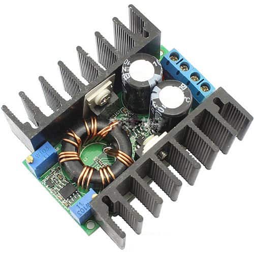
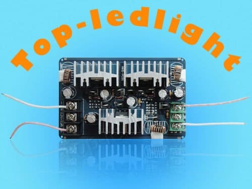
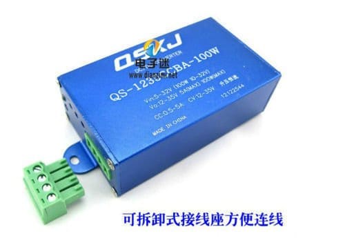
For the driver I'm looking at one of the following:

or

or

I need the driver to boost/step up voltage from 11-13v to the required voltage of the LED module, and in this case that would be 30-36V and of course be able to current limit the output.
But what I also want, that none of the drivers listed above provides is being able to dim, or set maybe 3 to 5 different intensities like 10%, 30%, 50%, 70% and 100%.
I would also like the driver and on/off-function to could be controlled by a reed/magnet switch to avoid running a switch through the watertight casing. Keeping the size down is also beneficial.
Is there any way you would think it is possible to modify the drivers listed? Or is it possible to build something like this by myself?
If you do have the time to consider a circuit like this it could be very helpful.
I am planning to have two separate light heads with one 100W LED SMD in each, and run them from the same battery. It is for video lights, so one light on each side of the camera.
If the control of these two lights could be controlled by the same switch it would be nice also 🙂
Great site btw, thank you for sharing all your information!
Kind regards,
Svein

The Design
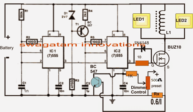
The proposed LED underwater light booster circuit with dimming feature could be build using a few 555 ICs as presented in the following description and the above circuit diagram:
The design is basically a controlled PWM generator circuit using a couple of versatile 555 ICs.
The one on the left is rigged as an astable for producing a high frequency square wave which is fed to the complementary IC2 555 stage wired in its standard PWM generator form.
IC2 responds to the fed pulses at its pin2 and compares it with the potential at its pin5 as set by the attached 10k preset.
The potential at pin5 set by the 10k preset voltage divider determines and varies the output PWM content at pin3 of IC2 by proportionately varying the duty cycle of the PWMs.
Lower potentials at pin5 of IC2 results in higher space ratio thereby forcing the LEDs to go dimmer and vice versa.
The above PWMs finally is applied to the gate of an N-channel mosfet which transforms the data into an amplified, boosted voltage across the LEDs with the help of the inductor L1.
The mosfet along with L1 forms a simple boost circuit which converts the 12V supply to the required 36V directly across L1 for the LEDs to get illuminated optimally.
The BC547 at pin5 of IC2 is positioned as a current sensor and controller, its base resistor Rx decides the maximum safe current allowable for the LEDs, and may be calculated as per the following formula:
Rx = 0.6/I where I is maximum current limit as per the LED specs.
How to Wind L1
It could be a matter of some experimentation. Begin by winding arbitrarily a few turns of 22 SWG magnet wire over a ferrite rod of any dimension. Connect it with the circuit and measure the boosted voltage across the coil (without connecting the LEDs).
Now simply divide the measured voltage with the number of turns used, the result would give you the turns per volt of the coil assembly. Next, its just a matter of optimizing the number of turns for acquiring the required magnitude of volts, which is around 33V in the proposed under water LED light booster, dimmer circuit.

Have Questions? Please Leave a Comment. I have answered over 50,000. Kindly ensure the comments are related to the above topic.
Hello Mr. SwagatamI the pwm is good but can’t get the current limiting stage to work. I think maybe I am hooking something wrong somewhere. The 12v lamp just stays at a steady brightness and a led with a 1k resister just blinks with no change to the brightness. Not sure where I’m going wrong. Here is the link again as I think is met to be hooked up ,maybe I am just getting something confused. https://drive.google.com/file/d/1DufJHyyuvfkZZwfHlCEnWxpU_e4oNjdY/view?usp=drivesdk
I know this is a bit overkill for this but plan on adding more leds down the line and also making another led light with 10watt leds. Thank you for you time.
Hello Jon, try shorting the collector/emitter of the BC547 and check if the LeD shuts off or not…if it does then the IC 555 stage is working OK. next at the selected overcurrent level check whether the current limiting resistor is developing over 0.6V or not across itself, you can check this by temporarily disconnecting the base of BC547 from this resistor..unless this voltage is developing the BC547 will not trigger.
By the way if the LEDs are showing a constant glow, that indicates that the current limit function is working and preventing the LeDs from getting brighter or from an overcurrent supply…
Hello Mr. Swagatam. First off I would like to thank you for all the wonderful work you do here. I have a little knowledge of electronics and have built a few circuits but I’m a little confused on the current limiting stage on how to hook up. I added the link to the circuit on how I think is what you mean by it. I also added a parallel 10ohm for rx to get me the 5ohm I need. Will that work? I am also going to used a 556 instead of the 555 as that shouldn’t matter. I haven’t figured out the inductor yet and was wondering if I should do the 32v or should I go 1v higher like I planed. I have almost everthing needed for the project and for the next few for Charing the battery etc… Again thank you for your time and consideration.
Hello Jon,
sorry I could not identify the comment thread you were discussing this earlier with me…?
anyway the current limit is calculated by the formula:
0.6/LED max current limit, so you just have to divide the 0.6 value by the max permissible current limit of the LED.
I would suggest you to first make and confirm the IC1/IC2 stages without the coil, by simply connecting a load such as a 12V motor or a 12V LED as the load. After this you can adjust the 500 ohm preset manually and check whether the load intensity varies accordingly or not.
Once this is confirmed you can proceed with the L1 experimentation…
Nice thread here…
But i’m a newbie here, i have question on diagram above.
What kind of D1 2v7.., is that a dzener diode? I can’t found that component at indonesia, would u like to give me how to change that component with other… For ex. In4007 or etc.
Please give me how the RX component value mean? Is that 100 ohm 1/4w?
Thanks
Thanks Hilman, yes it is a zener diode, you can also use a 3V or 3.3V zener here, you can replace it with 5nos of 1N4148 diodes in series, the polarity will just the opposite of the zener polarity.
Rx = 0.6/ LED current rating
thanks brother… you are the best, i am glad to hear your answer, this is the best site that i found.
but i still not to understand about Rx calculation (sorry…. coz of my stupid/i am learning basic electric by my self without school)
please give me what is the best value and watt of resistor that have to be used? i’m going to use this schematic to drive two Led epistar 100 Watt parallel at 12volt source of my motor cycle.. each spesification of Led is 32-34 Volt 3 Ampere…
and… .. have you PCB Layout of this picture? hihihihi..
thank you very much, and i’m verry sorry bad in english speaking… 😀
Thank you Hilman,
0.6V is the minimum triggering base voltage for the shown BC547 transistor.
Rx value is chosen in such a way that when the maximum LED current flows through it, the minimum 0.6V is generated across Rx…which makes sure that the BC547 is triggered, and pin#5 of the IC is grounded through it. this in turn shuts down the mosfet conduction with very narrow pulses at its gate. In this way the LED is saved from burning.
Rx formula is a simple Ohm law formula, which allows us to get a resistance value for generating 0.6V at the max LED current,
oh… okay, i got it (understand)
wow… this is the best result for your answer… i’m glad to know you are, thank you very much sir, i will borkmark this page so i could to explore your project.
now i’m going to make phone charger first at my motorcycle because i busy with my outdor job,
thanks…
my best regard
Thank you Hilman, glad you are enjoying my site!!
Please keep up the good work, and wish you all the best with the projects….
Yeah i’m interesting in this site, there are many helpfull project fo home appliance. But i didn’t see smartphone charger with high current. I need 5v 3Ampere car charger from 12v lead acid source with auto cut off protection.
i bought some buck converter likes lm2576 or xl2006 are not helpfull
OK did you check the following article?
https://www.homemade-circuits.com/dc-to-dc-double-cell-phone-charger/
please see the last diagram, you can use it for charging any cellphone but make sure to adjust the pot to get an exact 5V at the output first.
buck converter will some energy but can be a lot difficult to optimize and could be prone to input voltage fluctuation.
I will go today to get the parts from the other circuit, to try that one. Because with this one i can't find the fault, i measured all the connections last night and i connected it as the circuit shows. In the other circuit you said to replace R2 for a pot, must that be a 50k pot or a 10k pot with a 29k resistor in front of it?
the above circuit was successfully tested by me and as well as by the elecktor electronic engineers, …..although for some other application….
so it should work under any cost….anyway the other circuit would be more appropriate for you.
Yea, i know i do something wrong, i just don't know what 🙂 I like to learn this but here in Romania is it sometimes difficult to get the right components. We have one street on the other side of the city and there are a few stores who sell components. So i am something like 4 hours traveling to get what i need. But ok, we are used to stand in lines and walk a lot. With food it was in the past the same close for the revolution we sometimes had to wait 8 hours before the truck with bread arrived to supply the store. We didn't mind because we had a lot of fun. Before 1985 there was plenty from everything we had it pretty good in that time. If you come one day in Romania and you come in a row to wait for something, you will see the fun people have 🙂
I understand Claudia, and I am glad that you are determined to learn even with all the hardships, don't worry you'll succeed I can assure you that.
As for the other circuit, just make sure you are get a frequency at pin#3 of the IC…the easiest way to check this is to connect a headphone at this pin and hear for a buzzing sound, however this will be audible with around 1uf capacitor..so you can first start by connecting this higher value capacitor and confirm by hearing the frequency….after this you can go on reducing the capacitor value until there's no sound audible, same can be achieved by varying the upper resistor value…..but make sure not to reduce it below 1k….
But if i compare this circuit with the super capacitor charger, then in that circuit the pot meter should become between pin 6 and 7 from the 555 to regulate the voltage. Must in this circuit it not be the same then? Because here it is on pin 5. And it looks to me that the 557 is going to switch when the pot meter is now on 1/4. I don't know of course it is just my female logic that is talking here you know. What would happen when i take away T1, and r4 and replace that for a 100k resistor, then take away r5 and put between pin 6 and 7 from IC2 a 100k pot. Like in the super capacitor charger circuit. Do i get a big fire then?
the two circuits are based on different principles, so you cannot compare the part positions of the two circuits.
the super capacitor charger is much simpler and easy to troubleshoot and since it also uses the IC 555 you won't have to buy any thing new.
Well, i don't have the TIP122 and zener 17v for example. Can i use the mofset from this circuit instead of the tip122?
remove the BC547 and the zener network initially and check the circuit without them….TIP122 can be replaced by any suitable Nchannel mosfet….just reduce the gate resistor to 10 ohms
done it, the measurements on pin3 IC2 are now:
0V = 0.01kHZ
12.16v= 1.5kHZ
12.3v = 14.5kHZ
12.4v = 14.6kHZ
12.43v = 15.26kHZ
12.6v = 0.01kHZ
Do i understand it right that when the freq. becomes 10Hz that the coil then will load up maximal?
according to me the frequency should be constant throughout, it's the DC voltage at pin#3 of IC2 that must show a variation from 0 to max….
check with a small filament bulb, if it's intensity varies in response to the pot rotation, that would confirm the working of the circuit.
Well, if i turn the pot then the light goes on at 1/4 of the turn, but it does not varies in light intensity.
With the light bulp on it, i just measure a change from 0 to 9.5 v at once and then to 10.5v slightly when i move the pot.
I had told you to replace the 10k pot with a 1K pot, did you do this?
Yes mr. Swagatam, it is a 1k pot.
hahahha yea i am sure i do something seriously incorrect, but i am learning from this 🙂
euw, the Rx burned out again…and the 547.
I replaced both and removed the mofset now the measurements are a bit strange:
12.33v = 1.3kHz
12.4v = 13.2kHz
12.45v = 0.6kHz
12.5v = 0.55kHz
12.61v = 0.01kHz.
I measured between pin 3 from IC2 and –
with an incandescent bulb as the load the Rx will never burn, I am sure you are doing something that may be seriously incorrect.
for the time being eliminate Rx and the BC547…replace Rx with a wire link
I don't want to sound unpolite but i hope you can understand that i want to go on with this circuit to make it work.
OK as you wish, I was just trying to make your work easier…
It would be easier indeed, but i am now close to be done i think.
With the measured results what should i do now?
connect the mosfet as shown in the diagram, and initially do not connect the LEDs or the coil, instead connect a filament incandescent bulb, it can be any small flashlight bulb with voltage rating same as the circuit supply voltage.
vary the pwm and check the lamp response, it should dim and brighten….once this is confirmed then you can replace the bulb with a coil, use 50 turns initially over the selected ferrite core and measure the voltage across it at full PWM….reduce the number of turns proportionately if the voltage is too high
I had got one laying here.
Now the values are:
0.3V = 15.53kHz
12.1v = 16.35kHz
12.3v = 15.62kHz
12.4v = 15.41kHz
12.5v = 0.457kHz
12.6v = 0.001kHz
Lower then 12.1V i can't come, then it is going to 0.0v
you can try the above refereed circuit….for a PWM control you can make R2 variable and use it for the dimming function.
But that one goes to 16V and i need at least 36 volts for these LED's. The specs from the LED's are 38V 3.5Amp 100W. About the 3.5Amp i am not sure because that would make the LED 133W, so that is why i calculated with 2.6 Amp the Rx. And i have all the components for this circuit here already bought because i thought it fulfilled all i needed.
the coil turns decide the level of the boosted voltage….so just by increasing the number of turns the voltage can be boosted to any desired level.
Ok, i will go for it tomorrow, thank you so much already for helping me with this. I am not a electrician, but i want to learn it. But this project i need for my work. I bought 100W LED's for 3 point lightning for video documentaries. But i want it on 12 V because i want to use it on locations to. I bought some prints for it, the one's you showed on a picture to, but those go to 30V max, so i could just use 75% from the light (38v LED)….and two of them burned out. So this is why i am now busy to make this my self. but i like to do with a good mentor like you 🙂
In that case I think you should try the following circuit instead, because your requirement is much simpler:
https://www.homemade-circuits.com/2014/11/boost-charger-circuit-for-super.html
initially you can keep the T2 connection disconnected, and once the boost function is confirmed this may be restored with the required optimization.
Dear mr. Swagatam, i have measured it with the following results:
Battery is 12.6V
at 11.6v = 4.81KHz
at 11.8v = 4.72KHz
at 11.9v = 4.56KHz
at 12.1v = 0.01KHz
I don't come even in the neighborhood from the 30KHz.
I also just could get 21SWG magnet wire (0.8mm)
Dear Claudia, with a 180k, and a 1nF, the frequency should be around 8kHz…not 4kHz…so that's a bit confusing.
anyway, just change the 1nF with a 330pF cap…and check the frequency again.
21 SWg will do…first confirm the frequency then we can discuss the coil details…
Ok, that I can understand. I will look for a way to find somebody who can measure the frequency, i just have a simple multimeter and i measure with that one on pin 3 from IC2 a voltage from 0 to 11.7 volts with moving p1 while the battery is 12.3v when i have the mofset removed and the resistor and the bc547 replaced. But i will look for a rod for the coil, here we just have circle ferrite.
if the voltage is varying from 0 to max that very much indicates that your PWM is working good……if you can just confirm the frequency that would be great.
a ferrite ring will also do….initially you can use a filament bulb instead of the coil for confirming the dimming action.
mr. Swagatam, euwwww i made it on a euroboard, but at my first test the Rx resistor from 5.4ohm burned out and i measured 0 volt on the place where the LED should be. At my second test i replaced the Rx for a 1000 ohm 1W resistor and then the bc547 burned out when i turned the 1k potmeter a bit up, but at the output there was always 0,0 volt. What am i doing wrong?
It's because the inductor that you have used is incorrectly wound….a wrongly wound inductor will force high current through Rx and burn it…..if Rx burns then the BC547 will also burn….the mosfet will also burn.
so it's very important to first check and confirm the PWM at pun#3 of IC2 without connecting the mosfet stage….eliminate the mosfet and the LED and the inductor stage…and first confirm the PWM variations at pin#3 by varying P1 which must be a 1K (not 10K)
once the PWM is correctly determined, confirm the frequency which must be above 30kHz….only after this include the mosfet/ inductor stage, making sure that the inductor is wound over a ferrite rod and consists at least 20 turns @ 12 supply
mr. Swagatam, may i ask if the BUZ11 is the right equivalent for the BUZ10? Because here in my country no one got the BUZ10.
Claudia, BUZ10 (Id) is 23amp, whereas BUZ11 (Id) is 30amp so that's the only slight difference between the two….
Ok, that is good then. Thank you so much. When it works i will let you know and send you some pictures where i use it for.
sure, thanks!
Ok, thank you.
I made a part list from this project that i will share here:
R1=180k
r2=100
R3=470
R4=2k2
R5=100
R6=1k
R7=10
RX=
P1=10k
C1=1n
c2=10n
c3=1uF
C4=10n
BC547
BC557
D1= 2V7
D2=1N4148
BUZ10
IC1 = 555
IC2 = 555
that looks fine! just make P1 = 1k preset for a better response.
Hi Claudia,
The result for the formula I = 0.6/R will be in Amps…..not in mA
sir please help me. I want to make a mobile power bank with charging facility. Sir I have seen all your circuit diagram of dc mobile charger.In all circuit we input 6v to 12v battery.These batteries contain high weight and better for use in home or where these batteries are available but in journey like train,bus etc we cannot bring this method.we need a small and low weight devices.So please sir show me a circuit diagram for it.input power can be 1.5v to 3.7v.sir please take serius and reply soon.I am searching this circuit from 3-4 months.
utkarsh, you can try the following suggestion:
https://www.homemade-circuits.com/2012/11/homemade-cell-phone-emergency-charger.html