In this post I have explained how to scavenge discarded microwave oven parts for making a useful soldering iron heat controller circuit which can then be used for maintaining controlled heat over a connected soldering iron tip ensuring safe soldering operations, that may be quite crucial and handy if you are working with SMD parts.
By Henry Bowman
Warning ! This project could expose the experimenter to hazardous voltage from the high voltage capacitor. Only people with electrical knowledge of ac voltage hazards and high voltage capacitors should attempt this project.


Using Discarded Microwave Oven Parts
Do you have an old microwave oven that no longer works ? Well, don't throw it away. If the display panel and touch buttons still function, it can be put to good use. Some cheap microwaves may not have adjustable power levels. If you are unable to adjust power level to 50%, you won't be able to use this microwave.
Most defective microwaves are the result of bad magnetron tubes, defective high voltage diodes and/or high voltage capacitors.
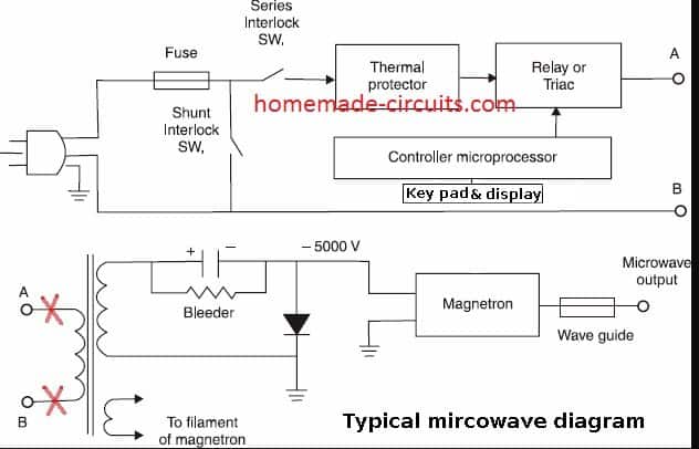
Soldering iron tips don't have long life, when plugged in for extended periods. This project will allow you to set various power levels to your iron and automatically disconnect the iron with the time you set. Look at the functional block diagram of a typical microwave.

How Microwave Oven Circuit Works
The leads marked with red X's show the ac connections to be cut. The processor controls the amount of time that voltage is applied to the primary winding of the high voltage transformer, depending upon power settings by the user.
If 100% power setting is selected, a relay or triac provides voltage to the transformer for 100% of the cook time selected.
If 50% power setting is selected, the processor provides a 50% on time and 50% off time to the transformer. Some microwaves can provide as low as 10% power level with 90% off time.
The transformer provides the high voltage to energize the magnetron, which provides the heat to the oven. For this project, we're only interested in the line cord, fuse, key board, display and processor and power leads to the transformer. There is no danger of radiation exposure from the magnetron, when the microwave is unplugged from the ac source.
The outer metal cover should be removed from the microwave, being careful not to touch any parts inside until the high voltage capacitor is discharged.
Make a note of the wattage rating of your microwave, before discarding the cover. Using a metal screwdriver with an insulated handle, locate the high voltage capacitor and place a short across the two terminals of the capacitor. A momentary spark may occur if the capacitor is still storing a charge.
Extracting Parts from Microwave to Make Soldering Iron Controller
The processor board usually has a ribbon type cable to the key board and lcd panel. The wires from the processor to the high voltage transformer primary will be large gauge wires that must be cut.
Clip the wires as close as possible to the transformer primary. The primary is the small coil winding, while the secondary is the large coil. The ac line cord must have continuity from the ac fuse to the processor panel. This will require removing interlock switches, thermal switch and any other switch that would prevent ac continuity.
Depending on make and model, the fuse may be located on the processor board, or elsewhere in the enclosure. You may have to remove a large plastic panel that contains the keyboard and display panel. This panel can be cut down to size to fit the enclosure you build.
A hacksaw or dremel tool would be the best way to reduce the size of the panel. Your enclosure for this project should contain the keyboard and display panel, mounted externally, and the processor board and ac fuse internally. It should also contain the auxiliary a/c outlet for the soldering iron, or other device you wish to control.
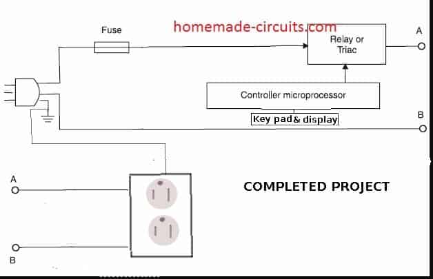
The two leads you removed from the primary of the high voltage transformer should be connected to the auxiallary outlet on your enclosure. The hot side of the ac, from the processor board, (usually black) should connect to the side lugs which connect to the small vertical blades on the outlet. Twist on type connectors can be used to splice the wires if longer lengths are needed.
Use the same gauge wire as the original wiring. The neutral wire (white) should connect to the opposite side lugs for the larger vertical blades on the outlet. The green wire from the ac cord should be spliced and connected to the green lug on the outlet which connects to the small round female holes. A completed project diagram is shown for your information.

Testing and Troubleshooting
When completed, plug in your line cord and test the panel. If it doesn't work, verify that you are getting AC mains to the processor board. You may have left some type of switch in series with the board that must be removed.
Depending on the purpose of the switch or thermal device, you may have to leave it disconnected and leave the wires open, or strap them together at the processor board.
Be sure you understand the purpose of the device that is preventing a/c from getting to your processor. Be sure that you have included the ac fuse in the circuit and it has not blown.
The auxiliary outlet for the iron should be labeled with the maximum wattage allowed, which you noted earlier. Once you have the keyboard functioning, plug a table lamp into your auxiliary outlet and set the power rating for 100% and time for 20 seconds.
Press the Start button on the key panel and the light should lamp for the time period selected, then automatically shut off. Change the power level to 50% on the key pad. The lamp should retain the same brightness, but flash on and off , with several seconds in between each cycle.
For immediate soldering iron use, plug in the iron and set for 100% power. Set the amount of time you need for the project, then press start.
If you need to take a short break, reduce the power level to 50%. When you return, reset the power level to 100% for a quick heat up. You may decide that your iron may need higher or lower idle time power levels to maintain a warm temperature.
More Applications using Microwave Oven Parts
In the above discussion I have explained how to use parts from a discarded or damaged microwave oven to make a heat controller circuit for soldering irons, however you may also find many other applications using discarded microwave oven parts.
A small heating pad could be connected which could be shut off at the time you select. If your microwave has a power setting of 10% you could connect a table lamp that goes off and on for several hours.
This could convince potential burglars that someone is at home. You could plug in a small reading lamp by your bed and program it to stay on for the time you need, then turn off automatically. Remember to observe the maximum watting rating, provided by the manufacturer, when connecting appliances or other electrical objects. Do not connect ac motors, electric drills or other inductive loads to this outlet.
Need Help? Please Leave a Comment! We value your input—Kindly keep it relevant to the above topic!