A Negative Temperature Coefficient (NTC) thermistor is a device which is able to suppress switch ON current surge due to its initial higher resistance at room temperature.
However, as the NTC suppresses the initial surge current, it warms up causing its resistance to drop to nominal levels and this in turns allows the current to flow through it at an acceptable rate, and the connected load is able to work normally.
In this post I have explained how to use an NTC thermistors in circuits for suppressing surge current during power switch ON. We also learn the datasheet and the electrical specifications of an NTC.
Today electronics is getting more and more compact and light weight, it's basically due to the involvement of compact converters which have completely eliminated the age old iron cored transformers.
However, this had to come at a cost, these units became too vulnerable to switch ON power surges.
But electronics always has appropriate answers, whatever may be the issues. NTC thermistors were created exactly for tacking this, that is in-rush surge currents during power switch ON.
What's an NTC
NTC (Negative temperature coefficient) thermistor is a semiconductor that contains metallic oxides.
It displays an electrical resistance which has an extremely foreseeable alteration with warmth.
The resistance differs substantially with heat, much more in comparison to
normal resistors.
These are incredibly perceptive to heat change, very precise and interchangeable.
They possess a broad temperature envelope which enable it to be hermetically packed to be used in damp conditions also.
Main Features:
* Durability of service, superior stability
* Compactness, robustness, sturdy surge current resistance
* Quick reaction time to surge current
* Extensive operating spectrum
* Significant element constant (B value), minimal stay resistance.
How does an NTC Functions
An NTC is attributed with a special property through which it is able to raise its resistance significantly during power switch ON.
When used in electronic circuits this property helps blocking the initial surge currents in to the connected circuit.
However in the process, the NTC becomes relatively warmer, which brings down its resistance to lower levels such that the normalized safe power subsequently is allowed to pass over to the adjacent circuits.
Practical application:
Thermistors are commonly used as
* Inrush current limiters
* As Temperature sensors
* In the form of self-resetting over current protectors
* In self regulating heating elements
* Power Converters, switch mode power supply SMPS, UPS power protection
* Energy efficient lights, electronic ballasts and chokes,
* Many vulnerable electronic circuits, power supply circuits etc.
The following image shows an example NTC component:

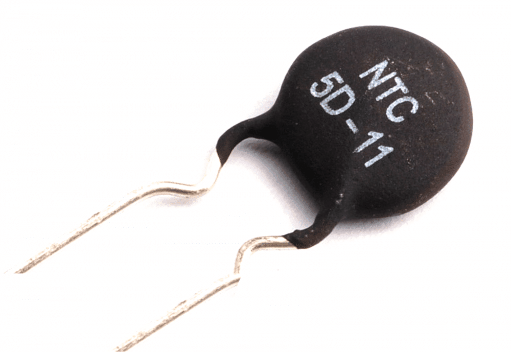
Identifying the NTC Thermistor from its Print Mark:
Before learning how to use an NTC thermistor, the users must first know to read the label and the rating of the device. The first digit "5" indicates the resistance of the part at normal conditions. Here it indicates 5 Ohms.
The subsequent alphabet and the digit indicate the diameter of the particular part, here it's 11mm.
How to Connect an NTC Thermistor in Practical Electronic Circuits
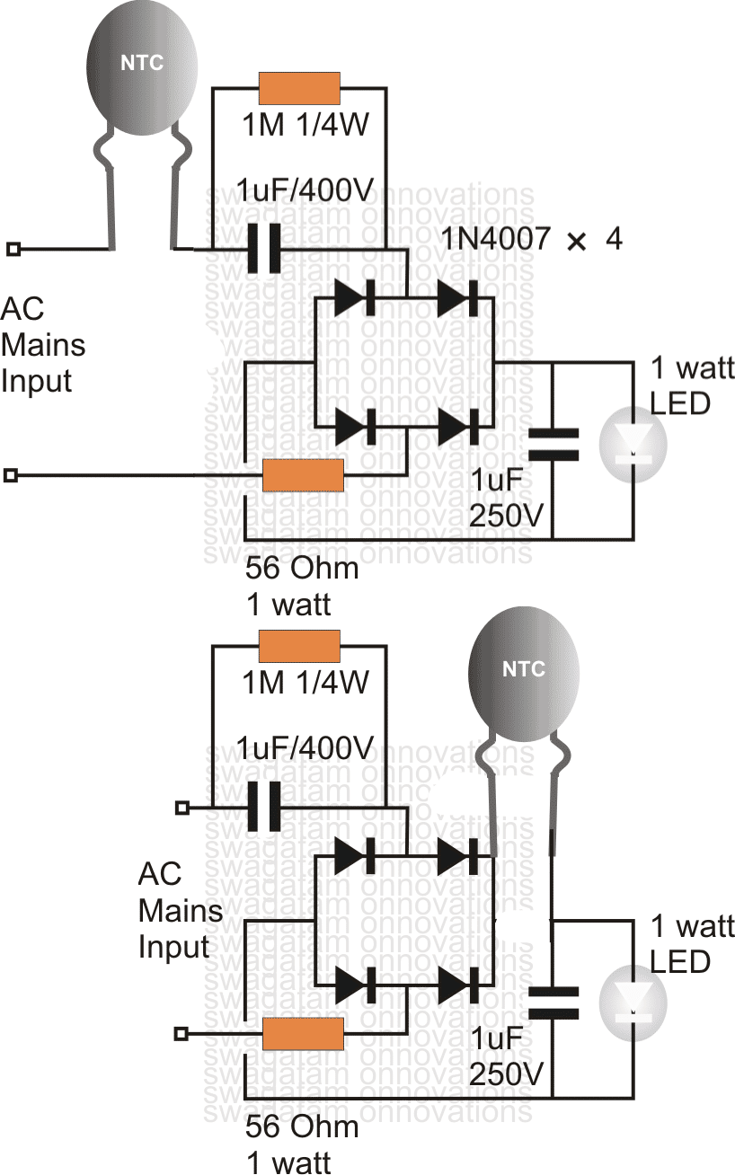
Normally in an electronic circuit an NTC is connected at one of the mains inputs, in series.
Alternatively, an NTC may be also used by connecting the device after the bridge rectifier, as shown in the following examples of surge controlled compact transformerless 1 watt LED driver circuits.
Filter Capacitors and NTC
The main issue related to current surges in switch-mode power supplies is a result of the large filter capacitors employed to filter the ripple in the rectified 60 Hz current before getting chopped at the high frequency.
The picture below shows a circuit generally found in switching power supplies.
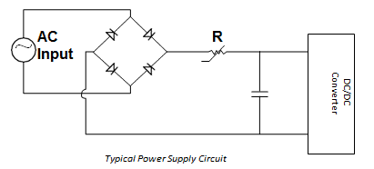
In this schematic the highest current during power switch on is the peak line voltage divided by the value of the resistor R.
For mains supply of 120 V AC, this can be roughly 120 x √2/R.
In the best possible scenario, just when Power is switched ON, the value of the resistor R needs to be much bigger, and quickly after once the mains supply is in its normal state, the R value must drop to zero.
An NTC thermistor is designed to work quite in this way, and therefore is best suited for most power supply application.
The job of an NTC is to limit the initial switch ON surge current by working like a power resistor that drops from a high value cool resistor to a low value warm resistor, the warmth being created by the normal current flowing through it.
NTC Considerations
A few of the aspects that needs to be considered while using NTC thermistor as an inrush current limiter are:
- Highest allowable surge current during Power switch-on
- Finding the equivalent thermistor size with respect to the the filter capacitors
- Maximum value of the current during it staeady state and normal continuous operation
- Highest possible ambient temperature around the thermistor
- Maximum expected life of the power supply
Maximum Surge Current
The major intent behind restricting inrush current is always to protect the electronic components that are connected in series with the input line of the DC/DC converter.
Generally, inrush protection inhibits annoying blowing of fuses or tripping of circuit breakers and sometimes burning or fusing of the of switch contacts.
Since the majority of thermistor elements are extremely ohmic at any assigned temperature, the lowest no-load resistance of the thermistor is computed by dividing the peak input voltage by the maximum permissible surge current in the power supply
Normal NTC Resistance = Vpeak / Imax surge
Turn-ON Current Surge
As soon as the input AC of an SMPS is switch-ON, all the associated filter capacitors inside the SMPS act like temporary instantaneous short circuit points, which store a charge equivalent to 1/2CV2 .
This sudden and instantaneous large inrush of current due to the the capacitors storing the charge has to make its way through the NTC.
Due to this the NTC temperature rises rapidly during this period, and as a result its resistance drops which ensures that subsequently when the capacitors are charged the NTC will stop restricting any further current and allow the current to reach the load normally.
The total time taken by the capacitors to charge optimally is dependent on the voltage.
The amount of current surge or power surge the NTC will be able to tolerate, fundamentally depends on the "mass" of the NTC.
The above logical view can be justified with the following expression and formula:
Input Energy = Energy Stored + Energy Dissipated
Pdt = HdT + (T – TA)dt
where:
- P = Amount of power developed inside the NTC, t = Time
- H = Capacity of the thermistor to heat up
- T = Thermistor body Temperature or the Dissipation constant
- TA = Ambient temperature
During the brief moment while the capacitors are charging (normally lower than 0.1 second), hardly any power is dissipated by the NTC.
Almost all of the input energy is adjusted as heat within the thermistor body.
In standard charts for inrush current limiters you can find outlined an advisable value of maximum capacitance at 120 V and 240 V.
This rating is not really meant to specify the overall capacities of the thermistors; rather, this indicates a practical value over and above which there can be some decrease in the life span of the limiter device.
Maximum Steady-State Current
The maximum steady-state current rating of a thermistor is mainly decided by the practical life of the power supply unit, for which the thermistor is being used and selected for protection.
In the steady-state situation, the balance of power in the differential equation explained earlier boils down to the below given heat balance formula:
Power = I2R = (T – TA)
As higher and higher current passes through the limiter device, its steady-state working temperature increases and its resistance decreases.
The highest current rating corresponds to the maximum permitted temperature.
In the standard inrush current limiters tables you will find a list of resistance values with respect to the load for each device, and also a recommended optimum steady-state current.
These ratings are dependent on standard PCB heat sinking, without considering the air ventilation, within a ambient temperature of 77° (25°C).
Having said that, the majority of power supplies include a reasonable air flow, which means a further increase in the the safety margin in addition to what is actually included in the maximum current rating.
In order to derate the maximum working steady state current with an increased ambient temperatures, you may make use of the below shown equation:
Iderated = √(1.1425–0.0057 x TA) x Imax @ 77°F (25°C)
Hi Mr Swagatam,
I would like to share my test result with the 170uF capacitor. I see the opening screen and when pushing the the choice “start” I can see the menu screen / session. But as soon as I choose the option “temperature” the screen collapses and the result is black screen. However as the next try I measured the voltage over the 170uF capacitor then I saw the continuously increasing voltage from 60 to 190V then I cut off the circuit. I think all the 220 voltage is being accumulated on the capacitor.
Hi Suat,
You must measure the voltage across the load, not across the capacitor.
As we discussed previously, the electronic system is shutting down because it is detecting an initial high voltage.
Please check the voltage across the load wires, it should be 120V.
Also check whether the capacitor is heating up or not….if not then it is fine…
Swagatam, as you advised, I measure the voltage of the load (air fryer) and it is about 220V AC. The capacitors are not heating up. I see the opening signals (a few beeps) and and the “start/stop” option on the display. But after the about 10 seconds the air fryer shuts itself off and the AC voltage increases.
Hi Suat,
If the voltage across the air fryer is not dropping to 120V, that simply means the device is not switching ON and accepting the AC 220V input.
As I suggested previously, the electronic circuit inside is quickly detecting the 220V and shutting off the system, so it is not possible to use this concept for your device, mainly because of the electronic shut-down feature of the equipment.
If suppose you connect only the heater coil of the equipment with our circuit then the voltage will quickly drop to 120V and the device will work as intended…
Thank you Swagatam, at least I have been learning something new. I dismantled the device and tested the the heating resistance and the voltage was about 140 AC.
(I am not sure this is normal or higher than the necessary) As the result, That is not too much important and I would like not to keep your time too much but is it possible to exclude the shut-down feature or increase the its resistance value? (For instant it may be the TL431 or similiar topology controlling the input voltage.) So, thank you very much one more time and please do not waste time if it would be the issue for you since I know the difficulty of the remote controlling / repair as the master of the such circuits.
Thank you Suat,
Yes, that looks better, with 140V drop the heater coil would be working good. You can try using a 150uF capacitor to drop the voltage further down to the required 120V.
Yes, there might be some voltage sensing stage in the shut down circuit which could be tripping the system, which could be eliminated for the heater to work normally with the 220V input AC.
Hi Swagatam I am not sure on how to express my gratefulness for your kind support for this and also about in the past and so far. The followings are limited due to over 10 messages. So I opened new header. I have used the lower capacity (474K 400V) capacitor and double parallel 100 ohm resistor before the relay upon your advice. It seems that the problem is solved and I think this is the minor problem. Now is it possible to increase the capacitor rate from 135 to 170uF and test the result?
No problem Suat,
Can you confirm if the relay is operating after a little delay, maybe a fraction of a second late after power switch ON?
If yes, then you can use the 170uF capacitor now….
I hear the click sound of the relay at the beginning and I hear the another click sound when the power is off. But as if there is no little delay but simultaneously runs with the start. Or I am not able to catch that activity at the first start. However if the switch is off then I am able to hear little delay of the relay.
There should be some delay happening when power is switched ON, because of the 220uF capacitor. The 220uF has to charge first, and only then the relay can activate…but the delay could be in milliseconds, that is why it appears undistinguishable…
No problem you can still try using the 170uF capacitor now…
Or if you have a 1000uF/50V capacitor, you can try that in place of the 220uF check the response…
Hi Swagatam;
You had advised me to use 5 Ohm 10A NTC (or double 10 ohm 5A) for the serial connected 170uF capacitor and 110V air fryer under the 220AC, so today I went to capital city center market of my country and no one has the NTC with the 5A capacitiy. And also I checked the local internet market but they all are used to giving diameter and resistance value not current capacity of the NTCS. In the case you would advise to stop the activity or suggest a new solution?
Hi Suat,
In that case you may have to build a small soft-start circuit, which will require a relay, a 1uF/400V capacitor, bridge rectifier and the 170uF/400V capacitor. Let me know if you would like to include it in your circuit.
Thank you very much Swagatam, I appreciate. I would like to complete my work indeed and learn something new(soft start). Could you please give me the detail or the page of your site?
P.S.: We had tested the 110AC air fryer with the 150uF and it was successful.
No problem Suat,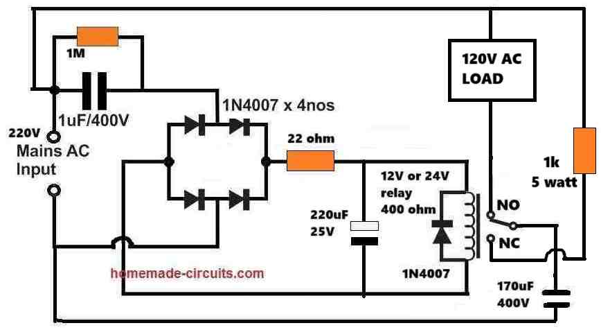
You can use the following soft-start circuit for your load to suppress the initial surge without depending on an NTC:
" rel="ugc">
I would recommend trying first with the 150uF capacitor in the above circuit instead of the 170uF, and confirm the results.
Thanks Swagatam for your kind support. I have 24V relay but about 1K5 and also I have 0.39uF and 0.47uF capacitors. Is it possible to use 2 of them as the parallel connected instead of the 1uF capacitor. And I have 2X50uF + 2X35uF (totally 170uF) capacitors. Is it possible to use first time 135uF for the test since the heating element(1000W) is not active while the initial start.
Hi Suat,
Yes, you can do all that you have mentioned, to adjust the capacitor values…no problems at all, just make sure the capacitor voltage ratings are as described in the diagram. 1.5k is also OK…for the resistor…
I am sorry Swagatam but the 1K5 resistor value in my previous message was for the relay resitance(not 400 ohm). However Is it possible to use 2K 5W resistor instead of the 1K 5W resistor at the load side?
No problem Suat, understood! a 1.5 k relay will also work. And for the 1k 5W resistor, you can easily replace it with a 2K 5W, no issues…
Swagatam here is the test result; I use 2A main fuse before the circuit and the capacitor value is 135uF, then I see the some beeps and the warning “start/stop” message on the display. All seem good so far but when I shut down and reopen the circuit, the 22 ohm (I used 33 ohm) protector resistor is always blown up.(I hope that was the expected result) Now please I remain for your latest instruction / advice?
Thank you Suat, for the detailed update!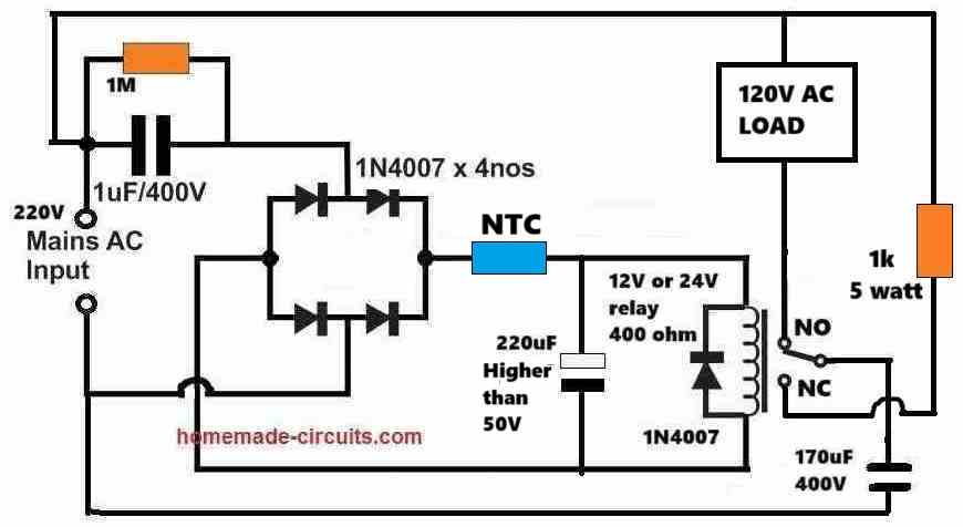
Please try replacing the 33 ohm resistor with a wire wound 33 ohm resistor maybe 1 watt or 2 watt.
Or you can replace it with any 1 amp NTC, which you may have with you.
" rel="ugc">
….also the 1uF/400V can be replaced with a 0.47uF/400V since the relay coil resistance is high (1.5k)
Hi Mr. Swagatam;
I have 220AC 1600W analog oven. I also have some NTCs at home. Is it possible to test the current of the NTCs by using them with the oven?
Hi Suat,
You can test your NTC with that load, if your NTC starts getting hot, that would mean your NTC is not 5 amp or 10 amp rated.
Hi Mr. Swagatam;
I need a 10 Ohm 5A NTC. Is the item NTG05-010 at the farnell datasheet list proper for the purpose?
https://www.farnell.com/datasheets/3217126.pdf
You are correct Suat, it is NTG05-010…
Hi Mr. Swagatam;
How can we know / understand the current rate of the NTC? Or Is it possible to connecte them in serial or parallel?
Hi Suat,
It will printed on it as code. You can get all the information from the datasheet: You will have to connect it in series with the 150uF capacitor.
https://www.farnell.com/datasheets/3217126.pdf
Thanks Swagatam. I had meant by saying “connecting in serial / paralel”: If we have double NTC, is it possible to connect them like the resistors? (serial and parallel connection of the double or more NTCs)
Hi Suat,
You can connect NTCs in series and parallel, but make sure that the thermistors have similar characteristics (e.g., resistance vs. temperature curve).
Dear author
Hello author, I sincerely thank the author for the article I just read, I am a mechanical repair technician, so I also have a passion for learning about electricity and electronics, through this article I hope the author will share with me some basic, rudimentary knowledge about electronics in general and electronic circuits in particular so that I can read and understand the basic circuit diagram,
Sincerely thank the author
Thank you PT,
I appreciate your interest.
This blog has many circuit designs and concepts dedicated to newcomers like you, which you can try.
If you face any problems understanding the concepts, you can always feel free to comment under the post to get quick solutions from me.
Hi Swagatam, I am looking into a circuit simulator to the one above. Filter Capacitors and NTC. Would you or have you ever made a circuit that will allow me to input a 120v Ac voltage to a 2 volt dc, 20 milliamp led Optic coupler? Your circuit looks very close to what I would like to accomplish. So, I have saw this done, but no values shown. The circuit is setup, Ac in to a 3 watt resistor and then what looks like a MOV to neutral. Then after the resistor something that looks like a capacitor and then into a Bridge rectifier. The positive output of the bridge rectifier goes to the optic coupler LED. Then returns to the bridge rectifier. The other end of the bridge rectifier goes back to a LED indicator then to neutral. There is also a diode facing backwards with a resistor in parallel with the indicator LED. Sorry for the long explanation. Could you give me any information that may help? Thank you in advance.
Thank you Bill,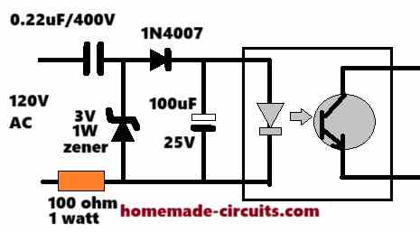
Sorry, I tried searching, but i could not find out the circuit diagram you are referring to. If you want to operate an opto coupler from 120V source, you can build the following circuit:
" rel="ugc">
My Small LED take 0.01A at 230V AC 50Hz. I want to connect NTC for more protection and long life. let me know what value recommend. Currently I am using 100 ohms resistance to protect the inrush current.
You can use the NTC which is shown in the above article.
Thanks noted well
I need to simulate an inrush thermistor (like 5D-9) in Spice — any clue where to get a model?
Sorry, no ideas about it.
LOW voltage ceiling fan Bldc fan In surge test NTC burnt. Could please give the solution to pass the 4KVA surge test .
If the surge is for a few milliseconds then a stronger and bigger NTC will work. If the surge is longer a few milliseconds then nothing can work to stop it.
Pls what could be the problem 220v to 24v smps,no output?
Your SMPS MOSFET might have burned. That could be the main cause!
Thanks for your reply Sir. Actually the amperage is 16 . the circuit connects one fridge and one TV ( Not LED TV old sony TV). Instead can I use TVS diode P6KE180A??
Hi Micheal, you can use TVS, but EVS diodes will control high voltage spikes, it will not control switch ON current surge
Dear Swagatham,
I used NTC thermister as per your circuit that after fuse towards the load. It works for a week or so after that it was totally burnt,.Tthis has happned twice the total watts of that circuit is 800 watts/220 ac. What would be the cause or shiuld I use higher capacity NTC??
Dear Michael, The NTC is in series with the supply line and therefore at 800 watts, the device may be subjected to a current of more than 3 amps (800/220). Therefore you will have to make sure that your NTC is rated to handle around 5 amp current so that it is able to withstand 3 amp current surge easily. Please check and verify the current rating of your NTC or replace it with an appropriate one.
A Negative Temperature Coefficient (NTC) thermistor is a device which suppresses switch ON current surge by resisting current through a temporary increase in its body temperature. “This increase in temperature occurs due to the sudden inrush switch ON current which in turn helps to increase the NTC temperature and cause an increase in its resistance value.”
The statement in “ “ is contrary to the nature of NTC which decreases in resistance value with temperature increase.
A statement in WiKi better explains the function of NTC.
• “As an inrush current limiter device in power supply circuits, they present a higher resistance initially, which prevents large currents from flowing at turn-on, and then heat up and become much lower resistance to allow higher current flow during normal operation. These thermistors are usually much larger than measuring type thermistors, and are purposely designed for this application.[22]
Thank you for the information. You are correct. I will make the necessary changes soon.
Dear Sir,
I saw the NTC circuit .you have shown AC input which one would be AC out put or to the load.
Sir,
Can I have a circuit diagram for surge spike controller. I am going to fix it inside the extension box working in regular 220V.
this circuit diagram must more than one MOV plus one NTC.
Also can I have circuit for 220v with TVS diode/
I am novice in electronics.
Thanks and kind regards
Michael, you can refer to the following article:
AC 220V/120V Mains Surge Protector Circuits
Yes sir thanks
but can you give me the values or types or code nos for the MOV and NTC?
please send a circuit using TVS diode for a 220V useage
Michael, you will have to visit the relevant datasheets and refer to the table/chart provided in the datasheet and compare the available data with your required specs and select the right one appropriately…..
Presently I do not have a TVS based suppressor…will try to find and update it soon
Dear Sir,
data sheet is too much for me cos i do not know much about electronics though I am interested.
Today I used MOV and NTC ans per your diagram. i think it works cos it did not blow up
Hello Michael, I understand, you can learn more only if you keep trying…I am glad the MOV circuit is working for you.
Thanks for the reference Swagatam.
And one more clarification. In AC can I use both MOV and TVS for better safety ?? And how to convert two TVS unidirectional into bidirectional??
You are welcome Michael,
you can read the following article for the required info:
https://www.mouser.com/pdfdocs/Semtech_Application_Note_TVS_Diode.pdf
thanks Swagatam.
and I want to send you one circuit diagram for your valuable opinion. Advice how to send it.
Secondly how to replace neon bulb to LED in a electric tester and what modification have I to do?
The easiest way is to upload the schematic on any free online image host, and then provide the link here, if possibly will try to solve it.
Are we sure that an NTC is the correct component? I think it should be a PTC, as an NTC will start at a high resistance and will reduce resistance as it heats up. This is exactly what you don’t want in this situation. A PTC does the exact opposite, it starts out with a low resistance and will increase as the temperature rises due to a current surge…
The risk of a surge current is maximum when power is first switched ON. An NTC provides a high resistance initially and helps blocking the power switch ON current surge. In the process its own temperature rises which reduces its resistance for enabling normal flow of current to the load subsequently.
Hello sir can run 6 number of 1 watt led in series on above circuit ….
Hello Abdul, yes you can connect six 1 watt LEDs in series….
Dear Sir,
I picked a trashed Panasonic micro dvd system model SA-PM50D.
On checking power board found that the main fuse blown and the 8 pin switching ic destroyed. The ntc 5D-9 also open. Some capacitors were bad too. Problem is that I do not the ic number.
I found the B+ supply is connected to the pin 7 and 8 through the switching transformer winding. I would appreciate if you help me identify this ic.
Thank you.
Hello William, guessing the IC number can be almost impossible, since there can be many such similar ICs with equivalent functioning specs
Thank you. Regards.
Good day Sir, please is possible to parallel ntc to increase current. Thanks
Hello Seun, According to me parallel NTCs should work fine, with an increase in current capacity.
Good day Swag, I used ntc to limit current to my Ac motor-375w powered by my inverter, after 3mins, my inverter(2kva) blew. Please what can be the cause.
Hello Seun, the inverter might have burned due to motor overload and overcurrent. When the NTC heats its resistance decreases, which allows more current to pass through it, this might have triggered the fault…
Please Sir, which simple overcurrent
Protection circuit can I use.
Which inverter circuit have you used for the motor?There should be a shut down feature in the inverter IC which can be used for the limiting….
Sir, i found this in search of the following: i am in need of a 11VAC (eleven volts) 100mA power input for a Hitachi turntable with apparently a DC Servo Motor – the unit originally plugged into the amp/preamp for it’s stable power, but i acquired it on it’s own, so what seemed to be a good buy at the flea market turned out to be quite a kick in the head, much more so than what i could’ve anticipated, but my daughter has been looking for a decent turntable for quite some time and i could not let this one pass – if only i knew beforehand LOL. …11VAC power units seems to be near impossible to get. I’ve thought of many things and what i’ve done so far (for starters to at least test if it is working) – i figured the power is just for the motor to turn the platter and so i hand rotated the platter and found everything is in good working order relating to the pickup and audio signal into the amplifier…. next i acquired a plain 230V to 12V transformer (1500mA) and figured that the 1 volt would not do damage but also expected that the speed will most likely be way off and it turned out exactly so (about transformer current rating, am i correct in thinking that the motor will only draw the 100mA from it [and the higher value will not neccesarily harm it?] ….. my google searches continued to find such component in south africa or get it shipped here, no luck of various kinds. So next i opened the 12V transformer in an attempt to check whether i could take some windings off the secondary to get the desired 11VAC… turned out as usual the whole thing was dipped in some or other resinous stuff, bit i think it is worth a try if i find no alternative….. in my search for alternatives i came across a banggood variac-like voltage controller, i also thought of utilizing a light dimmerswitch (either directly off the mains, OR off the 12VAC output of the transformer but they are also bit pricey – time and/or alternatives will tell) or sewing machine speed regulator. At the same time i took note of vfd (which may come in handy in woodworking hobbyshop) as well as options for a soft start for circular saw, grinder, router etc….. again being at the southern tip of africa it seems to be a struggle, there seems to be a Solid state relay type inrush current limiter and some install makita component for this purpose, no luck trying to get that here though…. and i came across the NTC option too, so i was quite puzzled that you say for 0.5HP motor it will not do…. i think SG333 thermistor can handle 12A, anyways, that is not my query in this way too long “comment/query” (sorry)…. i came across your “4 Simple Transformerless Power Supply Circuits Explained” post and thought YES, exactly what i need… i mean there are so many mains voltage LED lighting and other goodies nowadays without those bulky heavy transformers, only a tiny almost featherlight power supply “brick”….. one other point to be addressed i guess is the stability of the 11V (consistent 11V) supply…. it is at times like these that i always recall (and realise the truth in it) my highschool english teacher’s words “a little bit of knowledge is a dangerous thing” – please sir i hope you can spare some time and shed some light, unfortunately i do not know electronic/electrical engineering professionals to turn to and retail outlets of various kind’s personnel are just that, sales people. ,,,and then there are just so many variables and if i have an answer for this then another is unanswered …. My personality makes me feel a bit indebted already just for asking – please pardon this very long essay….but i thought let me give it a go, you wouldn’t have invited/welcomed queries if not serious/sincere. …greetings from cape town
dear Swagatam
I was reading with interest your blog, I discovered it yesterday. I’d like to ask you if you got a solution to protect a led circuit, 230AC / 120AC voltage , max 17w , reaching 5kv spike protection. Could I make it with a simple smd mov on the board? I don’t think, because I never found smd mov with so big energy. I can’t use condenser or other big components . Do you have any suggestion? thanks in advance for any reply.
Hi Stefano, Glad you liked my blog. It actually depends on the time for which spike exits. If the time is in microseonds, then an MOV will be able to handle it. When the MOV activates it short circuits the spike to ground, and in the course the 5 kv may drop to almost zero Volts, so 5 kv rating may not be too critical for the MOV.
You can get more info on this page:
https://www.littelfuse.com/products/varistors/surface-mount.aspx
thanks for your suggestion , Swagatam. The right Littlefuse component is a 26 mm diameter but is too big, there is no space on the board. Now we are using a mosfet STN1 800v to reach 1kv surge protection, ( Max linear suggestion , the old Exar company ) I think I have to work with active components to reach the goal.
but thanks for your support, I discovered a new Littlefuse component I could use in biggest circuit and following you we always can learn something new.
No problem Stefano, thanks for your feedback!
Can I connect a NTC on above update circuit diagram.
Which type of wire I will be use for led series.
yes you can connect an NTC for added safety
Please sir give me a hints about wire size, which is perfect for led series.
you can use any flexible wire.
Thanks sir,
What is the value of NTC for 90 LEDs.
Which type of wire I will be use for the led series
you can try the one shown in the below link
https://www.homemade-circuits.com/using-ntc-resistor-as-surge-suppressor/
Hi Swagatham
Please clarify:-
1). I think “275VAC, X2” BOX TYPE ( specially designed for AC supply ) capacitors safely inplace of highvoltage rated 400V dropping capacitor. What is your openion.
2). Is it three terms are same or different….Surge current , Spike and Zero-crossing, related with capacitive supply…?
I assembled the first circuit before one year, with my own modifications. Circuit worked perfectly. I used one 20mA high brightnes blue LED. My dropping capacitor was only a 224P, 630V Polyester type. I added a 9V, 1W zener diode at output and 1K resistance series with LED. 56ohms, 1W surge/spike limiting resistor replaced with 100ohms, 1W.
VERY USEFUL MODIFICTION……..the capacitor 1mfd, 250v electrolytic parallel with LED, I USED A 2200mfd, 16V ELECTROLYTIC CAPACITOR. This modification is highly useful at sudden powerfalure situations. Due to the holding charge inside 2200mfd (you can use high value, such as 3300mfd, 4700mfd etc.) LED will stay ON morethan 2 minutes after you switch OFf circuit /powercut, and gradually OFF the LED.
I removed all parts of a burned CFL and inserted your circuit inside it’s cover. If it is difficult to fix a single 4700mfd inside CFL cover, use 1000mfd x 5 pcs parallel. This will save space.
(There is a printing mistake in your circuit. 1mfd, 250V is shown as NONPOLORISED. It should be an ELECTROLITC type.)
Regards
Hi Anil, here are the answers:
1) There’s no specially created AC or DC capacitor, as long as the voltage rating of the cap is well above the supply peak it is well suited for that application…and for AC it must be a non-polar.
2) A surge may happen during a spike in voltage, because current will only surge when there is a sudden increase in voltage. zero crossing is the period when the AC wavrform is passing through the zero level of its waveform, switching a gadget during this point is considered to be the safest because the AC is in its most weakest level at this zero crossing point.
for enabling a emergency light effect you can increase the series resistor value of the LED, which will further increase the backup illumination of the LeD during a power failure.
the 1uF in the diagram is correctly shown, it can be a polar or non-polar doesn’t make any difference, I have shown it as a non-polar because a non-polar capacitor is more commonly available in the market and is more compact than an electrolytic.
is a type of capacitor that has no implicit polarity — it can be connected either way in a circuit.
yes, a capacitor with no polarity can be connected any way round in a circuit
sir is there any circuit which can supply dc to a circuit for 1 min only when allready connected dc supply is intrupted for very short periods like 40 sec ,1min .
i want system like ups but for very small circuit like 555 timer 12v circuit. i want this supply system max for 1 min not more than that.
please suggest me something
thank u
Hi Gurmel, you can probably try the concept presented in the following article:
https://www.homemade-circuits.com/2013/03/simple-dc-ups-circuit-for-modemrouter.html
thanks yasar,
sorry I am not sure about the calculations, it could be a bit complex.
you can refer to the following couple of articles, and may be try to derive a suitable format of the PFC design
https://www.homemade-circuits.com/2016/03/power-factor-correction-pfc-circuit.html
https://www.homemade-circuits.com/2014/02/simple-1-watt-to-12-watt-smps-led.html
thank you very much swagatam, its very useful and can you suggest me how to improve the power factor for the 5 watts single LED driver
you can use it with the following circuit, this will be more suitable:
https://www.homemade-circuits.com/2016/07/scr-shunt-for-protecting-capacitive-led.html
upto 500mA max by using more input caps in parallel…output voltage will be 310V DC but current will as per the value of the input cap..formula is explained here
https://www.homemade-circuits.com/2015/01/calculating-capacitor-current-in.html
sir can it help to reduce inrush current of motor ?if yes
than can u plz suggest me ntc or ntc rating for given details.. 3hp motor inrush current is 40amp runnnig current is 14amp voltage is 230 single phase.
Gurmel, I don't think there's any NTC that may be designed to handle 40 amps….instead you can try connecting a high wattage resistor in series, in conjunction with a delay relay,
when switched ON the resistor will allow 50% current to reach the motor causing a slow start, meanwhile the relay will trigger after a 1/2 second and bypass the resistor to enable an optimal current for the motor
but sir how to know rating of resitor to decrease current upto 50,
is thereany formula you can suggest with example?
yes, through Ohm's law
R = V/I
220/15 = 14 ohms
wattage = R x I^2
14 x 225 = 3150 watts
the wattage looks unnaturally huge.
since you would want to use it only for a split second, a relatively smaller wattage resistor could be tried.
Hello I have an Inverter with 1kva ,whenever I connect it with a Laser printer (600watt) the inverter takes more current as inrush current ,at that time the voltage fluctuation take place .Can i use this circuit for it
Hi, The inverter consumes more current because the printer asks for it, if you don't allow the inverter to take current from the battery, the printer will not start normally.
moreover an NTC is designed to handle current only for a few milliseconds. beyond that it itself might get burnt or get destroyed so it cannot be applied for your application.
Initially at power switch ON the NTC resistance will be higher, since its temperature would be lower, however after power switch ON the NTC will gradually heat up due to cuurent flow through it enabling it to lower its resistance until eventually it reaches to its specified level.
A relay bounce cannot have any significant effect on an LED if the LEDs are protected with a limiting resistor or with some other form of current limiting stage.
An NTC stats of with the rated Resistance and after the initial surge the current and the heat ( as a function of I Squared R) will heat up the NTC (that's why it is called a negative temperature co-efficient )and damage form the surge is eliminated . I have used properly rated NTC to protect Ac driven LED bulbs especially those that more prone to damage like LDR (Light dependent Resistor) based relay circuit that turns ON the light during nightfall . Here the problem was a bit more acute because of the relay bounce . all relays bounce as they make contact . In this particular case I lost couple of 220 v ac based LED bulbs. Since then no more LEds Bulbs lost. Was able to fix those LED Bulbs too .. because it was noted that 1 among the 36 , 3 Volt LED was blown out within about a month less than 20 turn on's associated with relay bounce which i would say was the main contributor
Great i take a lot of my time and moments to find how block surge current in sircuit but when i see this article i am got woundered really a ntc can be candidate as final option in capacitive power supply i understand it and make it good.
Thanks! I am glad it helped you!
This article is very useful to me as i have seen only on PC SMPS and i was wondering what this component was but now i know what it is, thank to you sir. Sir i have a SMPS @450watt which the fuse was blown, so i replaced the exact fuse rating(5amp-250V) but when i turned the SMPS on the NTC was blown, i can't find the exact NTC rating which is "1F-72 5D-9" so sir can i replace it with this one "NTC 10D-9" Thank you.
Thanks Lima, if the fuse and the existing NTC blew up then you must first find what caused these hazards, until you have determined the fault it wouldn't be a wise idea to replace new NTC or fuse…….check by connecting a 40 watt lamp in series, if the lamp glows brightly that would indicate a possible short circuit or some other similar fault inside the SMPS
you are welcome -S…a NTC would surely help to keep the LeDs safe…additionally you can try adding an inductor wound over an iron nails for the same, in series with the LED….use around 200 turns of any thin super enameled copper wire on an iron nail…inductors can be excellent surge suppressors for DC circuits
According to me it's only during the initial power switch ON when the capacitor is fully empty, and acts like a short circuit when introduced to mains inrush.
During this time it gets charged to the mains level with the first cycle, and subsequently the opposite cycle only discharges the capacitor to the level as determined by the load specs, if the load is 12V rated then the capacitor is now discharged and charged at this limit, until it's switched OFF and switched ON again or if there's a major voltage fluctuation.
Most probably You can find the current of the NTC in its datasheet
LED got burnt with NTC included?? or without an NTC
Thank you -S,
Here are the answers to your queries:
1) The surge current will be always equal to the maximum AC mains input current…so it could be 200amps or even 1000amps, but it's not the amp value which becomes crucial rather it's the period for which it's allowed to pass through the capacitor, this in turn depends on how quickly the capacitor gets charged. Lower value caps will charge quicker than higher value caps producing quicker charging and consequently lower average surge current….which could range normally in microseconds.
2) I am not entirely sure about the NTC current but mostly it could be within 1 amp at 220V…so it's better to install at the 220V side of the circuit.
For your application you can effectively use the first circuit from above…use two 105/400V in parallel for achieving 100mA
Sir
Can i use ntc directly in series with my half bhp water motor? Presently i have ntc 10d9 22d9 and 33d9 in my stock. Can i use them? If not please suggest any suitable.
Sir
Can i directly connect one ntc in series with my half bhp water motor? Presently i have ntc 10d9, 22d9 and 33 d9 in my stock. Can i use them? If not please suggest any suitable.
No, the NTC is for low current applications, it won't be able to handle 0.5 hp motor….you may have to employ a PWM soft start kind of circuit for implementing the high initial current surge protections.
Sir
Thank you for your advice on how i say it does not compensate. The only thing I can do. Can I pray for you. You always have wealth.
there's no way to check whether an MOV is actually working or not,,,,but in most cases it will perform as expected from it.
pray for the world!…God bless you!
Sir.
Can i use MOV 10D471k or Which value would be safe to use?
Satheesh, please check the clamping voltage of the MOV from its datasheet….if it's around 330V to 400V it would be fine.
Hello sir, I have a charging fan that uses NTC 10D-9 in its power supply. It was a new fan and it worked fine for one month and after that its fuse burnt out so I replaced it with new one but the new one burnt out as soon as I turned on the switch. I have tried to search for the short circuit but there is any short circuit. now I believe that it is because of NTC it is not limiting the current. can you please guide me that what ever i m believing is right ?
Hello Aneel, an NTC is connected in series to the input line, so it cannot be a cause of a short circuit, still you can remove it and check by connecting a 100 watt bulb in place of the fuse, if the bulb glows and the fan does not move, then surely your fan could be the culprit.
Ok thanx sir
Sir i want to run 300 leds of 5mm or 8mm to 230v AC main of 6 series in parallel means each series of 50 leds so wat will be the changes for the circuit
use 2uF/400V instead of 1uF/400V
Sir can I use 50 nos of 5mm leds in series for this circuit I have blinking leds (dual color led) like red blue and red green
yes you can use it.
Sir' very tanks.
Tanks Sir'
1.can I put only 20 or 25 LED(5mm) in the circuit?
2. Sir can you more better (1or2watt)LED circuit ask me?
yes 25 to 39 5mm LEDs will also work, but you may need to change the input capacitor to 0.47uF/400V
for higher watt LEDs you should opt for SMPS driver
CAN 5D-11 NTC BE SUFFICIENT TO BUILD A CIRCUIT THAT CARRY FROM 40A – 60A LOAD
NTCs are used for protecting electronic circuits, not for high current loads.
Ok sir But it can at least suppress surges on refrigerators and air conditioners
You can use industrial MOVs to suppress high voltage, but NTC cannot be used for high current loads, unless you have an NTC that is specially built for high current applications.
Dear swagatam'
1. How many give LED(5mm) in this circuit?
2.Can you a very better LEDcircuit ask me?
pls help me.
Dear Hassan, you can add upto 90 LEDs in series for a 220V input, and 45 LeDs for 110V
Sir'
I have got thermistor DSC(10 D-13).can I change c2(1uf 400v).
pls reply
yes you can do it, no problem…
Dear sir'
no NTC(5 d_11) in my area
what i will do?
Dear Hasan,
I think your local retailer will know better regarding a standard equivalent, or alternatively you can try using a hand wound coil for obtaining the same results.
wind 500 turns of any thin super enameled copper wire over an iron bolt and use in series with the LED.
Hello swagtam , bro I have 1 9w led driver I want to add ntc in this for better protection. Can u plz tel me where I can ad ntc in main connection on phase or nutrel actually on line point it already have fuse resistance so cn I ad ntc on nutrel point. ?plz clear my doubt.
Hello Manoj, An NTC can be added on any of the input terminals, whether it's phase or neutral doesn't matter, you can even connect it in series with the fuse, nothing is critical as long as the device is in series with the supply line.
thanks sir another question is that if i use 4 no of 5 watt led instead of 20 no of 1 watt leds for making an illumination of 20 watt cfl can this circuit work
4.bp.blogspot.com/-e4z26LacoE0/UyAwhV1_YUI/AAAAAAAAGd0/3pFdlNxV9PE/s1600/1+watt+led+driver+circuit.png
May be you did not understand what I suggested in the previous comment. In capacitive power supplies using less number of LEDs will reduce efficiency and light….using more number of LEDs will improve.
Therefore it would be better to use 20nos 1 watt LEDs instead of 4nos 5 watt LEDs which will not give any illumination
….more LEDs in series will improve…and less will reduce the efficiency and light
thanks Sir,I do as your answer ita woring very well.
Another Question is that if i connected single 3 watt Led instead of 4 1 watt leds can this circuit work
4.bp.blogspot.com/-e4z26LacoE0/UyAwhV1_YUI/AAAAAAAAGd0/3pFdlNxV9PE/s1600/1+watt+led+driver+circuit.png
Another ? is that can single 3 watt led is equal to 3 1 watt leds
Harjot, using less number of leds in series will make the circuit less efficient and using more numbers in series will improve its efficiency.
a single 3 watt led will produce an illumination of just 0.5 watt LED with the mentioned circuit
for perfect results you should go for an SMPS AC/DC adapter with a current control stage.
yes a single 3 watt LEd = 3 x 1 watt LED
Hello Sir,can you haveSMPS AC/DC adapter with a current control stage
Hello Harjot, presently i don't have but I'll try to post one related article soon, if possible….
which circuit isbest for home usage with 4 1 watt led
4.bp.blogspot.com/-Ao044-f_094/USJX2xXmq9I/AAAAAAAADLw/QXbrfjnDjHc/s1600/surge+protected+led+driver+circuit.png
vs
4.bp.blogspot.com/-e4z26LacoE0/UyAwhV1_YUI/AAAAAAAAGd0/3pFdlNxV9PE/s1600/1+watt+led+driver+circuit.png
Put NTC in the second circuit and use it for getting best results.
Hi,
I need this circuit use for 7 or 9 High Power LED in series, so what I need to changed. only the resistance power increased or change the value as well?????
connect the leds in series, no changes would be required, use it as it's given in the diagram.
Sir,
can i put 10sp 005 thermistor in that Circuit? I already have that..
PLZ……..
I can't interpret its resistance value, you can try it, because slight variations in the resistance won't affect the circuit outcome shown above.
Thanks
Sir,
What Is the resistance value of that NTC…..
PLZ….
Avik, The one which is shown in the diagram is exactly what is required for this circuit….. in fact it's suitable for all 220V operated circuits.
sir i want to ask you two questions the first one I have deleted all of the thermistor how to identify the value and power of it, the second I want to know how to lock the increased flow of tiristor thermistor protected thanks
I don't think it can be measured with a DMM, we have to depend on the manufacturers spec sheet for knowing the details of these devices.
…sorry could not understand the second question?
When it comes to capacitive power supplies there are many things that needs to be considered. Just taking care of the zero crossing won't help
here we need to exploit the voltage rather than the current, because here we have plenty of voltage and less current.
Avoiding current means avoiding surges, so we have to thing of using minimum current which can be achieved by connecting LED in series.
For 20 watts instead of using a single LED, we can go for 20nos 1 watt LEDs in series, that would restrict the max current need to 300ma, quite achievable with smaller caps.
Next we also need to employ some sort voltage regulation by including 7812 or similar device in the circuit.
But ultimately as you have mentioned an smps is always good for anything that exceeds 100mA usage….and I have always recomended the use of an smps for making high watt LED drivers
yes it can be a good solution to the ever present surge problems in capacitive power supplies, I'll try to come up with a suitable circuit soon, and update in this blog.
Thanks!
Thanks for ur reply sir,
Can we add more 1u400v cap in parallel. If yes then any change with 56 ohm resistor and 1u250v in output
No adding more caps will not help much unless you make the total forward drop of the LEDs to near 220V.
Hello sir,
How r u.Its long time to have some discussion with u
I want to use ten 1watt led.can the above circuit is capable of this.
I had 10d-9 ntc can i use it for above circuit.i had seen some smps for powering dth and similar using
this value 10d-9 ntc.
Thanks
I am fine Avijeet, thanks!
The above circuit will illuminate 10 one watt LEDs in series but the glow will not be optimal due to lower current from the cap, yet still it would be considerably dazzling.
yes the referred NTC will do the job
200V, 1 watt
it's not critical, you may apply any value above 10uF, but the voltage rating should be above 50V preferably.
yes 50 Leds 8mm will work with a 105 cap.