In this post I am going to explain different types of electrical transformers that are used in a wide variety of applications.
Transformers can be classified in many different ways, for example: based on their input / output character, voltage, frequency, application, power handling capacity etc.
In this post we will be exploring all the major types of transformer which enables our modern life.
We are going to explore:
- Transformers based on their input and output voltage.
- Transformers based on their material construction.
- Transformer based on their application.
The above classification will be further subcategorized into several branches and we will illustrate with the help of block diagrams. But before we jump into the article let’s try to understand what a transformer is?
What is a Transformer?

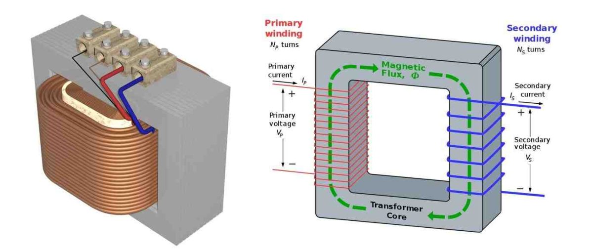
A transformer is a passive component typically consisting of two or more windings wrapped up on a core material which transfers electrical energy from one winding to another winding or to multiple windings through electromagnetic induction and mutual induction.
The primary function of a transformer is to increase (step-up) or decrease (step-down) the output voltage.
Typically a transformer provides galvanic isolation between input and output circuits.
All types of transformer work primarily on alternating current (AC) and also can work on pulsating DC current. No transformer can operate on continuous / pure DC current.
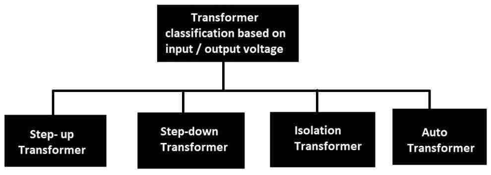
Transformer classification based on input and output voltage:
Step-Down transformer:
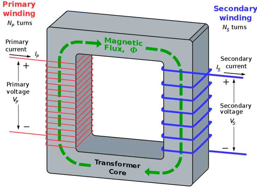
A step down transformer consists of a core material like iron, ferrite or toroid; the primary winding (where the input is applied) will have more winding than secondary winding (where the output is supplied).
Due to the lesser number of turns of winding at secondary side the output voltage will be lower than the input, but the current will be higher than the input, ideally the power input and power output will be the same.
Step-up Transformer:
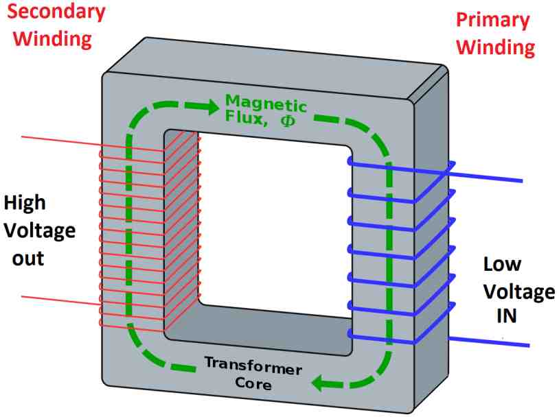
The step-up transformer does the inverse function of a step-down transformer.
The number of turns of winding in the primary side is less than the secondary winding, due this the output voltage (at secondary side) is higher than the input and the current is lower than the input.
Still the input and output power is ideally the same, this is true for all types of transformer.
Isolation transformer:
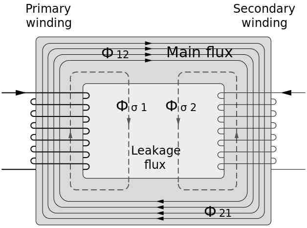
The primary function of an isolation transformer is to provide galvanic isolation between input and output sides.
Galvanic isolation means there is no direct contact between the input and output circuits, but still it can transfer electricity via other means, in a transformer the energy is transferred using alternating / pulsating magnetic fields. Galvanic isolation also exists in step-up and step-down transformers.
The number of windings at primary and secondary sides are equal and hence input and output voltage, current, power are ideally the same but practically there will be some loss in the form of heat and this is true for all types of transformer.
Auto transformer / Variac / Variable transformer:
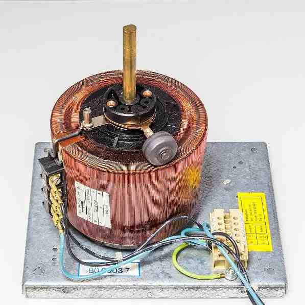
An auto / variable transformer is a type of transformer that can vary its output voltage by rotating the provided knob. We can step-up or step-down the voltage as we wish.
Unlike the conventional transformers that I have explained till now, the auto transformer has just single winding. The input and output act on the single winding, hence NO galvanic isolation between input and output.
- Step-down configuration:
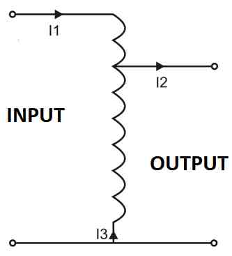
The above illustrated schematic is of an auto transformer in step down configuration, it has single continuous winding and the output is taken in between the winding.
- Step-up configuration:
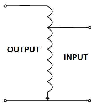
If we reverse the input supply we can achieve a higher voltage than the input. Practically we don’t need to reverse the supply; instead we just need to rotate the armature which sweeps across the winding to give us the desired voltage.
This type of transformer is used in low and high power voltage stabilizers, where a servo motor controls the armature and provides a stable output voltage.
Transformers Classification based Core Material
A transformer can be classified according to material used in the construction of the core. There are three major types of core material: iron / steel, ferrite and air.

But, before we dive into the classification let’s understand why a core is necessary for a transformer?
The core of the transformer is responsible for constraining the magnetic field within the transformer and conducts the magnetic flux from one winding to another with minimal flux loss. It provides a low reluctance (resistance) path for the magnetic field to flow.
Without the core, the magnetic field from the primary coil will spread into surroundings and only few magnetic flux lines reach the other coil winding. The core also provides structural strength to the transformer.
Soft Iron and silicon Steel core:
The common types of transformer core materials are iron and steel used in low frequency operation 50/60Hz. The soft iron and silicon steel has good magnetic permeability without getting saturated, meaning it can get magnetized easily but does not retain the magnetization after removal of the magnetic field.
The transformer core is not constructed with a single continuous block of material; instead thin sheets of insulated soft iron or silicon steel (illustrated below) are stacked and the coil windings are wound around it, this is to reduce eddy current effect which will waste energy as heat.
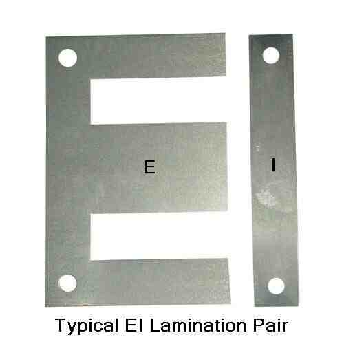
Ferrite based Transformer Core:
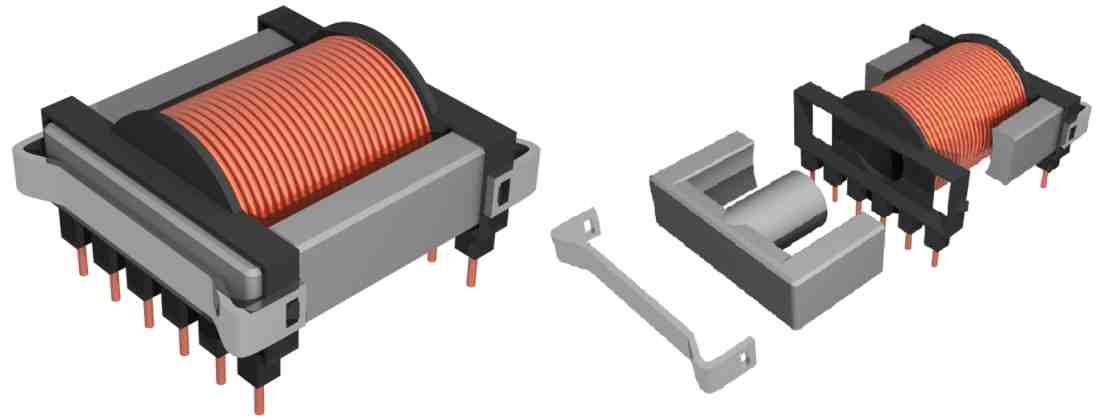
Ferrite is a ceramic material made by blending iron oxide with oxides or carbonates of zinc, nickel, magnesium or manganese.
The core of the transformer can be made using a continuous solid block of ferrite, since ferrite material is non-conductor, no eddy current losses like iron or steel cores.
Ferrite core based transformers are used in high frequency applications like switch mode power supplies and RF applications.
Ferrite cores can be manufactured into any shape or size we desire. Ferrite material is brittle like any other ceramic material, hence the care should be taken while transporting and dropping it on a hard surface will cause damage to the core material.
Ferrite core transformers can handle a lot of power in a small footprint compared to iron core type, the drawback of ferrite core transformers is that they cannot operate efficiently on low frequencies like 50 / 60 HZ.
Air core:
Air core transformer as the name suggests it utilizes air as core for its operation. Air core transformer’s coil windings are wound on a plastic material and more stiff wires are used for its structural strength.
Air core transformers have less inductance but have low core-loss compared to other types of transformer where core material causes some loss, however other losses like dielectric loss exist.
Air core based transformers are used in radio frequency applications, the air core permits higher quality factor or Q-factor for the signal.
Air core transformers are also used where high magnetic field strength is required (above 2 tesla) and due to the absence of a core material we can achieve zero magnetic saturation which is not possible with a core material.
Transformer Classification based on usage:

Transformers are used in a wide variety of applications and particular names are given to such application specific transformers.
We are going to explore the topics that are mentioned in the above categories. There are few other types of transformers which are not covered in this post because of their limited usage.
Instrument Transformer:
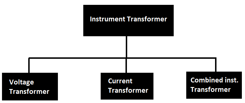
Instrument transformers are the category of transformers where they are used for measuring electrical parameters. Instrument transformer is further classified into three categories:
- Voltage transformer.
- Current transformer.
- Combined instrument transformer.
Voltage Transformer:
A voltage transformer is used for measuring high voltages; it provides good galvanic isolation between high voltage line and measuring components.
Voltage transformers are connected in parallel to the supply and they have high impedance primary winding so that they don’t load the supply.
The primary and secondary winding voltage ratio is made linear for accurate measurement and usually follows step-down winding configuration.
The voltage transformer can also have multiple secondary windings for measuring and protection circuits.
Current Transformer:
The current transformer as the name suggest is used for measuring current and it will be connected in series with the power supply.
The primary winding consists of just one for few windings and the secondary winding consists of several windings, the output at secondary winding is proportional and linear with primary winding’s input current.
The core of the current transformer is usually a toroid (round shaped) where the primary winding just passes through it and the secondary winding will be wound on the toroid as illustrated below. The secondary winding may have several taps depending on the application.
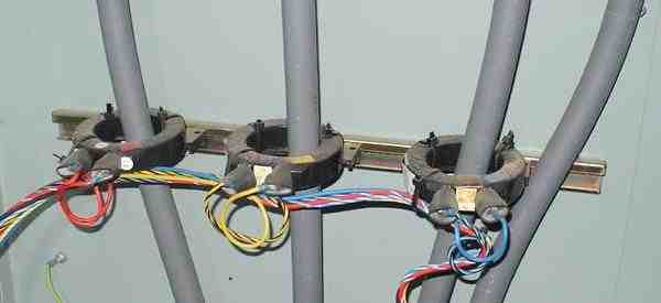
In measuring instruments it is common to find a current transformer in the form of a clamp that can open the core and close around a wire that needs to be measured. The above image shows a permanently attached current transformer.
Combined Instrument Transformer:
A combined instrument transformer utilizes both voltage and current transformers in the same body and it is used widely in sub-stations for measuring electrical parameters for protection systems and even for estimating revenue.
Using combined instrument transformers in substations reduces the physical footprint of the transformer.
This concludes the discussion about the instrument transformer.
Trigger transformer / Pulse transformer:
A trigger transformer also known as pulse transformer is predominantly used for driving circuits with optimized parameters at the output side.
A pulse transformer is optimized for transmitting rectangular pulses, which essentially means fast rising and falling pulses.
Pulse transformers are used for driving MOSFET gates, IGBTs and digital circuits. A medium sized pulse transformer is used for controlling flash circuitry of cameras. High voltage pulse transformers are used for generating high voltage pulses in Tasers, radars, particle accelerators etc.
RF Transformers:
RF transformers are the type of transformers used at radio frequencies. The RF transformer is further divided into 4 types as illustrated below:

- Air core transformer:
In the previous section we saw what an air core transformer is, it is used in RF applications. The air core transformer consists of just a few turns of winding soldered directly on the PCB.
Since there is no core material its inductance will be very low and due to this air core transformers can achieve very high frequency and due to mutual induction like any other transformer primary winding energy is transferred to secondary winding depending on the transformer's winding ratio.
- Ferrite core transformer:
In one of the previous sections, we saw what a ferrite core transformer is and it is not only used in power electronics, it is also widely used in RF applications.
Ferrite core transformer is employed in RF applications for impedance matching and the transformer consists of just a few turns.
Impedance matching is very important in RF applications, because if impedance is not properly matched between two RF circuit stages, it can cause inefficient power transfer and signal reflections which we must suppress as far as we can.
- RF transmission line transformer:
RF transmission line transformers are made using twisted pair cables, co-axial etc. which is wound on a ferrite core or other types of core material.
This type of transformer is utilized to achieve transmission of wide band signals where the transformer needs to efficiently transfer low and high frequency signals instead of being selective at one or few frequencies.
The core of the transformer increases inductance by several fold, hence increases Q factor. The RF transformer is also used for matching impedance between two RF stages.
- Balun Transformer:
Balun transformer is made for interfacing between balanced and unbalanced RF circuits.
The Balun is placed between source and the load and it is a two port component and it can convert unbalanced signals to balanced signals and the opposite of this is also true. It can also provide impedance matching between source and load.
This concludes our discussion about RF transformers.
Power Transformer:
Power transformer is the type of transformer involved in transmission and distribution of high voltage / high energy supplies for commercial and residential purposes.
Power transformers include: iron core transformers, autotransformers, isolation transformers etc. which we already explored in one of the previous sections.
In this section we are going to explore specifically about transformers that are used in power generation and distribution and here are the types:
- Polyphase transformer.
- Phase shifting transformer.
- Grounding transformer.
- Variable frequency transformer.
- Polyphase Transformer:
Polyphase transformers are the type that can handle multiple phases in one transformer for stepping down or to stepping up the voltage.
Polyphase transformer consists of multiple single phase winding and below is the illustration of a polyphase transformer with cutout view.
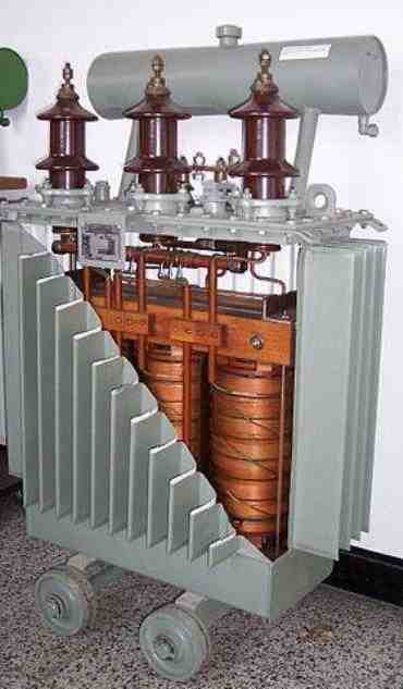
The common type polyphase transformer is a three phase transformer who’s primary and secondary windings are connected in delta and wye configurations as illustrated below.
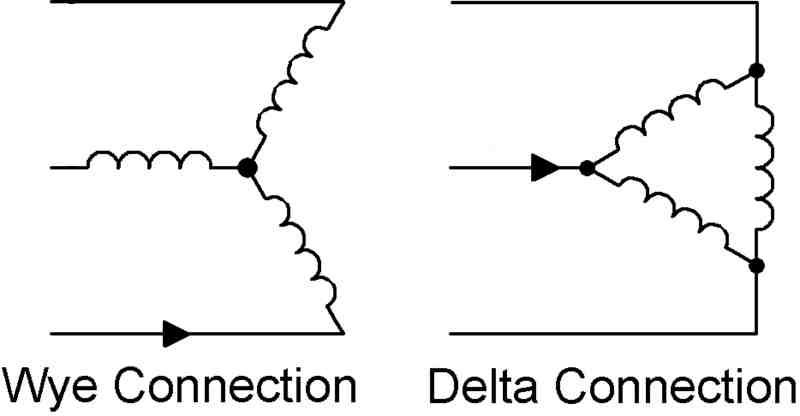
The transformer’s primary and secondary windings can have the above configurations in any combinations like wye-wye, wye-delta, delta-wye, delta-delta.
Wye configuration has 4 terminal points; the 4th point is the middle where three windings meet; it is also used as return path (neutral) in unbalanced loads.
- Grounding transformer / earthing transformer:
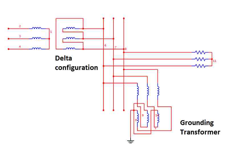
Grounding transformer also known as earthing transformer is a supplementary transformer used in three phase power systems for grounding.
It is used for providing ground (return) path for delta and ungrounded wye system.
Since delta configuration does not offer a neutral point for a load, we need this type of transformer working alongside with a three phase transformer to provide a neutral point, so that a load can be connected between phase and neutral. They also provide a low impedance (resistance) path to ground.
- Phase shifting transformer:
Phase shift transformer also known as quadrature booster transformer that can shift phase angle of its output. It is used to control the flow of active power / real power of a three phase transmission system.
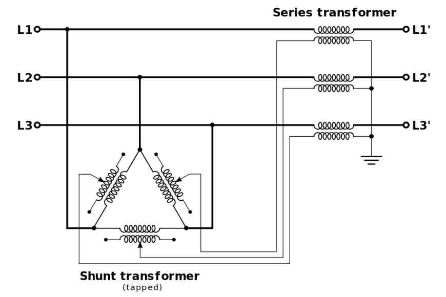
Let’s consider a grid that distributes power to two places namely A and B, when power requirement at A is more compared to B, more power can be sent to area A by manipulating phase angle of alternating current and reliving overload situation.
When there is more power required at area B when compared to A, phase angle manipulation can be done to satisfy the need of B.
In conclusion, the phase shift transformer balances the power on a grid by distributing it.
- Variable frequency transformer:
VFT or variable frequency transformer is used for transmitting power between two unsynchronized AC systems.
Unlike DC systems where two similar voltages can be connected in parallel directly with the help of diodes, an AC system cannot do this without proper synchronization; otherwise we will end up short circuit.
Unlike conventional transformers, VFT has a stator and a rotor which need to be rotated for its normal operation, so it is not solid-state. VFT is a new technology as of now.
This concludes about power transformers.
Audio Transformers:
An audio transformer is a type of transformer that is designed to handle signals ranging from 20 Hz to 20 KHz.
Audio transformers can eliminate DC components in the audio signal, it can also eliminate RF frequency interferences and they provide impedance matching for source and speaker which is essential for delivering maximum power at best efficiency.
Audio transformers can split an audio source into many and also can combine multiple audio sources to one.
Since audio transformers are magnetic components they can be susceptible to external magnetic interferences like power lines that carry 50 or 60 Hz mains power, this can be heard as humming noise in the speaker.
Audio transformers can affect audio quality because their magnetization at the core is not linear and also does not have linear frequency response.
Audio transformers are classified into few types:
- Loudspeaker transformer.
- Output transformer.
- Coupling transformer.
- Loudspeaker transformer:
A loudspeaker transformer is for minimizing transmission losses over a long distance where the audio source is far from the speaker (example public address system).
At the audio source, the signal voltage is stepped-up and far away at the speaker a step-down transformer is used that matches the speaker’s voltage specifications.
- Output transformer:
Output transformers are found in vacuum tube based amplifiers where it is used to match impedances. The tube requires a high impedance load, whereas the speaker is a low impedance load.
Coupling transformer:
Coupling transformers are used to interface different stages of an audio amplifier circuit. Their primary task is to connect two different circuit stages and yet electrically isolate them from each other.
Coupling transformers can be used for inverting a signal by flipping its output to the next stage and it is also for impedance matching.
This concludes our discussion about audio transformers.

Have Questions? Please Leave a Comment. I have answered over 50,000. Kindly ensure the comments are related to the above topic.
Hi Swagatam;
I have the transformer EMC model wjg-dc 6V 300 mA (DC 6V 300 mA I still see its advertisement at the media) I removed its original plastic cover for the first time I meant it was not repaired before however I see that there are 8V AC at the secondary side then only 4 diodes, in other words there was no capacitor installed but the place was allocated as the empty after the diodes. Could you please advise that if this is acceptable since the current rate is low?
Hi Suat,
Do you mean there was no filter capacitor? In that case the output DC will not be stable and clean and will include a 100Hz ripple content. Can you please tell for what application do you intend to use this 8V DC? I try to suggest.
Thanks Swagatam. Yes I mean there is no filter capacitor on the PCB. But I did not remember that this device was used for in the past. However I can use this adapter for the PIC Programming projects by adding one or double diodes more to slightly drop the voltage about the 5V.
Hi Suat, If you want to use the 8V DC with any electronic circuit, then you will need to add a filter capacitor after the bridge rectifier. A simple 1000uF/25V capacitor will do the job for you!
Hello dear swagatam
How can I power a 7 tapping auto transformer correct for voltage stabilization.
I got it from a 2000kva stabilizer
Hello Okongwu,
You can check the resistances of the tappings, and find out which one has the highest resistance. You can use this winding for supplying the 220V input, but make sure to put a 100 watt bulb in series so that in case of a mistake nothing burns.
After this you can check the voltages of each of the tappings to confirm their ratings.
Once confirmed you can use the transformer for any relevant application.
Hi Mr. Swagatam;
I have the 110V 60Hz airfryer (for cooking without oil) whereas our country electrical system
is 220V 50Hz. I am able to regulate the voltage from 220V to 110V however I am concerned
about the frequency which may be defective for the digital screen device of the circuit. So I
need your help / comment about the matter.
Hi Suat,
Although I am not sure, and i have not yet used an airfryer, I guess the digital screen is for displaying purpose only which can run on SMPS DC supply, so mains frequency might not be relevant to its functioning.
However, if there is some kind of timing involved then the mains frequency will become relevant and must be correctly matched.
thanks for the valuable feedback for me. So you think that 10Hz frequencies will not affect the input smps voltage and or the buck / boost convertors in the circuit.
No, I don’t think frequency is relevant to SMPS converters, because anyhow they convert the AC to DC at the input sde.
Sir,
Good afternoon,
I am tinkering with unipolar stepper motor and arduino. Can you please help me understand the basics of center tap in context of connections with arduino and ULN2003.
Thanking you for your time,
Regatds,
Hi Vishwa,
Sorry, i do not have sufficient knowledge regarding Arduino with stepper motors, so I am finding it difficult to solve this query. If possible I will investigate it further and let you know.
Sir,
Good afternoon,
Thanks for your prompt response,
Regards,
No problem Vishwa.
Hi Swagatam;
My transformer is 220/24 AC and about 4 Amps. Sometimes when plugged at the beginning in a short period a slightly sound is heard like a small diaphragm voice.
There are 2 outputs taken from the transformer, one with the bridge rectifier and filter capacitor goes to bench power station and other one with the 2 pcs of parallel mounted 105j capacitors and 7805 goes to the digital display for the bench power station.
The digital display connections are like that:
(+) pole is supported with 5 volts from the 7805. And (-) pole is connected to the bench power station common ground line. So, (-) output of the 7805 is also connected to the (-) pole of the bench power ground line.
My problem and question is:
As soon as I connect only the (+) pole of the transformer output to the bench power input line I hear an annoying sound like a vibration voice. And I think that recently the transformer output voltage have increased form 33 volts to 35 volts.
Best Wishes
Hi Suat,
Did you use a separate bridge rectifier for the two 105J capacitors, so that the output from this bridge can be connected to the 7805 IC? The negative of the two bridge rectifiers should be then connected in common.
Yes Swagatam; as per your instruction (you had issued the diagram) it has 4 pcs of 1n4001 bridge rectifier between the capacitors 105j and 7805.
OK good, in that case you circuit is fine, but anything higher than 35V can be dangerous for the 7805 IC.
35 volts is not at the side of 7805 but at the side that goes to the bench adjustable voltage circuit. However I can remove the filter capacitor of the transformer which goes to bench station as an input since the circuit already has the input filter capacitor (C1) then it may be decreased the transformer output voltage to 32 volts. As a result I think you do not consider the vibration void as important.
Exceeding 35V won’t have any effect on the 2N3055 transistor, or the other transistors since all of them are rated above 50 V, I hope.
If you find the transformer vibration goes away when the the circuit is disconnected from the transformer then it is a matter of concern, otherwise not.
Hi Swagatam;
My transformer input 220 V and output is 24 V. I think it is possible to gain triple output from the same transformer. 1- directly 24 V AC 2- by using the bridge rectifier 24 V DC output and 3- by using 105 capacitor (1 uF) before the bridge diode and any 78xx series after the bridge diode.
Thanks and regards
Hi Suat,
yes, definitely, all those configurations are possible from a single transformer.
Swagatam;
Ref. to above item 3, I have used the 7805 and placed 33uF and 104j capacitor at 7805 input and output legs.
However, my digital volt meter display light is very weak and blinking. So, it is possible to say; that the 7805 is defective or 5 volts is not sufficient as the dispaly feeding voltage?
Regards
Suat, Did you check whether the 7805 is generating 5V or not? If yes, then try feeding a 9V supply to the meter and test the illumination. If it illuminates brightly will confirm that the meter needs higher than 5 V for the display.
thanks Swagatam. The 7805 generates 4,93 volts. In fact i had avoided to desolder and resolder the pcb items. However my question is:
we had used 1uf capacitor before the bridge rectifier so if we should use a filter capacitor on the output of the bridge rectifier or not?
OK, 4.93 is almost 5V, so that’s fine….I am suspecting a low current of just 50 mA from the 1uF capacitor which may be causing the illumination issue. Yes, filter capacitor will be required after the bridge. The 1uF before the bridge is for limiting current and to ensure minimum heat on the 7805 IC, it will not do any filtration. You can try two 1uF in parallel to create 100 mA current and check if that solves the illumination issue.
Yes Swaqatam, after the second 1 uF it solves the illuminaton problem it is brighter now and filter capacitor also solves the blinking issue. Thanks i am gratefull
Thank you Suat, for updating info…Glad it is solved now.
Hi Swagatam;
My scrap transformer specs.:
Label Notes: 430-0172 LS-A8594-PT Z150H
Primer input has 4 wires
Secondary output has also 4 wires
Ohm values:
At the one side (brown-black-blue-white all thickness = 2 mm with the insulation material 18 awg)
Wire 1(brown) and wire 2(black) = 2 ohm wire 1 and wire 3(blue) = 2 ohm wire 1 and wire 4(white) = 12 Ohm
At the other side:
Yellow and orange wires = 1,5 ohm (their thicknesses are = 2 mm 18 awg ) and black and white wires = 0,7 ohm (thickness 12 awg)
Voltage values:
If 6 volts is applied to yellow and orange then there are about 90 volts output at the cross side wire 1 and wire 4. And if 6 volts is applied to black and white then I read about 175 volts at the wires 1 and 4.
This transformer should be Russian made and there is no extra information on the web.
Please you may share your opinion about that transformer if data is efficient for you.
Best Wishes
Hi Suat,
What exactly are you trying to find in the transformer, are you trying to find the 220 V taps?
I really do not have detailed information about the transformers. I also not sure that this is an ordinary transformer. However in the Russian page I met the clue as 8 V and 220 V and I think it is possible to gain 8 volts by using the primary input 220 volts and vice versa if input is 8 volts then output will be 220 volts.
Finally I do not have any idea about its current capacity.
Regards.
You can first try finding the 220V wires. This can be done by feeding 220 V AC randomly to the different sets of wires on both sides through a 220V 40 watt series bulb. The wire pair which cause the bulb to almost switch OFF will indicate the 220V winding.
Once the primary side winding is located, 220V can be fed to these wires, and an AC ammeter can be connected across the desired secondary wire pair, which is show the current capacity of the transformer. The reading must be taken quickly to avoid heating up of the meter’s shunt resistor, and the transformer.