A Wheatstone Bridge circuit is commonly used to measure resistance, inductance, capacitance, and impedance. These are made up of four parts or arms that are joined in series in a diamond like bridge configuration. These four arms carry the individual components such as resistor, inductor or capacitor connected across the fur junctions.
An alternating current (AC) or direct current (DC) is supplied between one pair of opposite junctions, and a display metre or an output circuit is coupled between the other pair of opposite junctions. With this arrangement when all the four components are adjusted to have equal values it produces a null or 0 reading on the connected meter. This is the basic working principle of a Wheatstone bridge circuit.
Main Features
Some of the main features of a bridge circuit are given below:
- Bridge circuits work on the basis of null-indication theory.
- The output of a balanced bridge is zero.
- The indication is determined by the calibration of an indicating equipment or the meter.
- Bridge circuits can be used to take precise measurements.
- Additional external circuits can be controlled by bridge circuits.
- One arm of the bridge may comprise a detector device sensitive to physical parameters such as temperature or pressure while working as a controller.
History
The Wheatstone bridge circuit is the most well-known and commonly studied bridge circuit in electronics classes. It is made up of a couple of parallel resistance arms, each having two series components, often resistors. To include a current source through the connection, a DC voltage source is linked between a diamond-shaped network. To identify a state of balance, a null detector, originally a cheap and reliable galvanometer, is attached between the parallel arms.
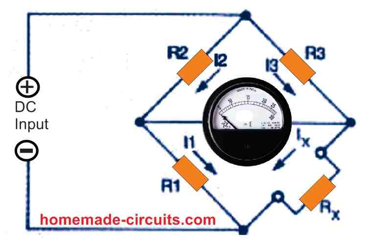
A researcher named S. H. Christie designed this circuit as shown in Fig. 1 above, in the year 1833. Its importance, unfortunately, was not appreciated until 1847, when Sir Charles Wheatstone demonstrated the method in which his bridge circuit could be used to produce reliable electrical measurements. This bridge circuit became renowned as the Wheatstone bridge as a result of his thoughts and experiments.
The Wheatstone bridge has most likely outlasted any previous electrical measuring tool. Although it is still a reliable and accurate device, it isn't as user-friendly as the latest digital multimeters. Nonetheless, the Wheatstone bridge is capable of providing upto a 0.1 percent accuracy.
The accuracy may be comparable to 3% to 5% error typically found in resistance values measured with analogue ohmmeters. Digital multimeter accuracy is determined by the meter's specifications, like DC voltage accuracy and resolution.
Wheatstone Bridge Calculations
When measuring an unknown resistor (Rx) through a Wheatstone bridge, one of the existing resistors is changed until the current passing through the null detector starts falling to zero.
The bridge can be now considered in a balanced state. This indicates that the voltage drop across resistor R3 equals the voltage drop across the unknown resistor Rx, and the two divider resistors R1 and R2 deliver identical voltages.
As a result, this operation can be expressed as given with the following equation :
(1) I1 x R1 = Ix x Rx
In the balanced state, the voltage drop across the resistors R2 and R3 should be equal, which would mean that:
(2) I2 x R2 = I3 x R3
In this balanced situation since no current flows through the connected meter, we can assume that:
(3) I2 = I1 and I3 = Ix
Replacing I2 with I1 and I3 with Ix in the first equation, we get:
(4) I2 x R1 = I3 x Rx
Now by dividing equation 2 by equation 4, we get:
(5) R2/R1 = R3/Rx
The above equation can be rearranged as:
(6) R2 x Rx = R3 x R1
Equation 6 above describes the conditions when a Wheatstone bridge's can be precisely balanced and may be used to predict the value of an unknown resistor after the bridge is reached the balanced condition. The most frequent Wheatstone bridge equation is obtained by dividing either sides of the equation by R1:
Rx = R3 x R1/R2
The original Wheatstone bridge was notable for its extremely high null sensitivity. When the bridge is powered by a 10 volt DC source, 5 volts is created across all resistors during balance condition, and the measuring device needle remains at the center. On a calibrated moving-coil analogue metre, a 0.1 percent movement results in a 5 millivolt readout.
This circuit may have a null sensitivity element (i.e., proportion out-of-balance sensing value) of roughly 0.003 % by using a basic null-detecting DC amplifier. Until the year 1847, the main disadvantage of the original bridge circuit was that R3 required to have a wide resistive range in order to balance all potential Rx values.
Wilhelm von Siemens, a German engineer could overcome this problem in the year 1848 by applying the changes depicted in Fig.2 below.
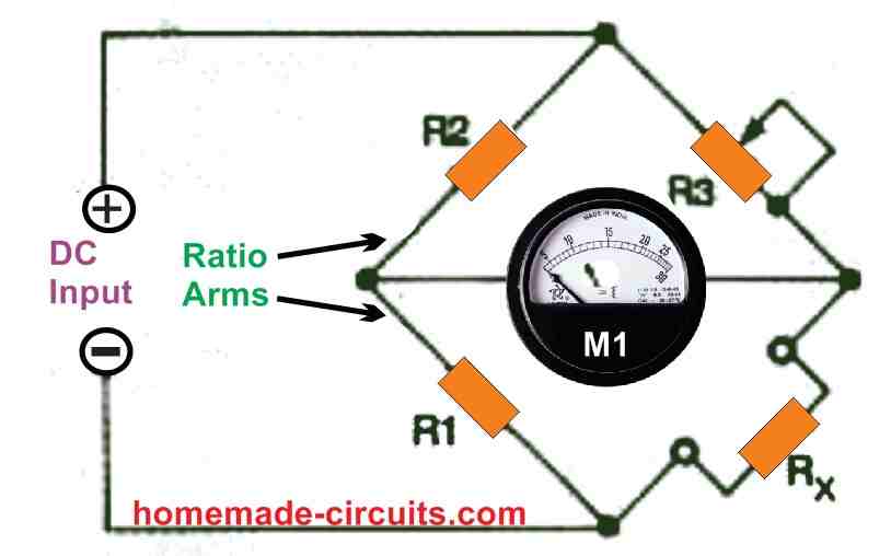
By setting R2 to a constant value and allowing R1 to be switchable, the bridge could be further enhanced as illustrated in Fig. 3 below. This design is based on a high-accuracy scientific measurement device from the 1970s.
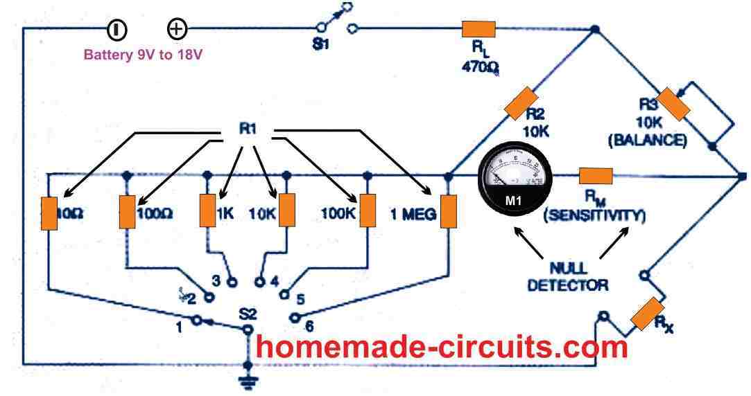
Switchable Wheatstone Bridge
The selector switch having six switchable decade ranges, as shown in Fig. 3 can be used to determine DC resistances between almost zero to 1 megohm. The sensitivity of the balance-detecting center-zero metre is governed by resistor R3, which is a standardized 10-kilohm adjustable potentiometer. Bridge current is limited to a few milliamperes by the value of the resistor RL.
The fundamental problem of this 1970 Wheatstone bridge is listed in Table 1below: its null sensitivity (which is equivalent to the Rx test voltage) worsens proportionately to the R1/R2 ratio's deviation from unity.
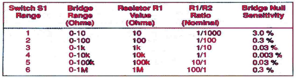
As a result, the minimum sensitivity is 0.003 percent on the 10 k range at which R1/R2 ratio is 1/1, but somehow it deteriorates to 0.3 percent on the 100-ohm and 1 M ranges where its R1/R2 ratios are 1/100 and 100/0, respectively. The Fig. 3 network must incorporate a sensitive null balance sensor in order to be a functional device.
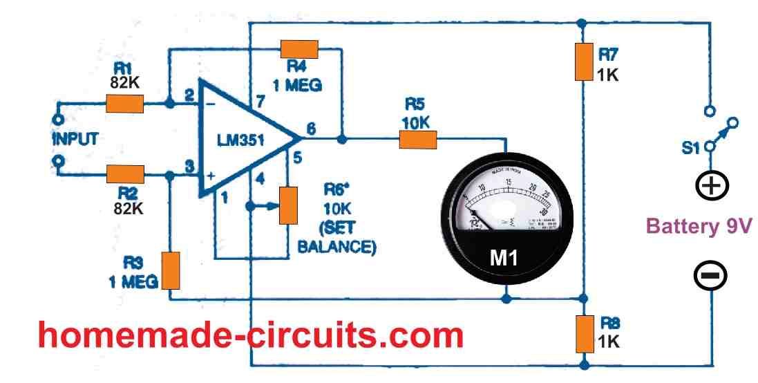
Figure 4 above depicts a design for an x10 DC differential amplifier that may be used in conjunction with an external analogue volt-ohmmeter to create one such detector circuit. This circuit requires its own separate 9-volt power supply.
The LF351 features a JFET input allowing low input offset voltage, and also BIFET technology for broad bandwidth and efficient slew rates with low bias currents, input offset currents, and supply currents. The LF347 is a twin counterpart of the LF353, and it is the rough equivalent of the LF353.
For low-sensitivity observations, an auxiliary volt-ohmmeter could be adjusted to its 2.5-volt DC range, or to its 50 μA or 100 μA range for high-sensitivity measurements. The circuit should be initially balanced in the 100 μA range by shorting its input connections together and tweaking the multiturn 10 k SET-BALANCE control for a zero deflection on the metre.
Variations in Wheatstone Bridge
Without compromising the essential balancing calculations, the Wheatstone bridge circuit of Fig. 2 can be constructed in different forms. Figure 5 below illustrates this.
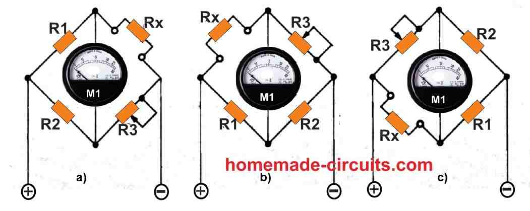
The bridge's ratio arms are designated as R1 /R2 in each configuration. It's worth noting that the signal-source and detector connections of the bridge can be swapped without causing the circuit's balancing equations to be disrupted. This is also applicable for different types of capacitance and inductance bridges.
The Wheatstone bridge version depicted in Fig. 5a is by far the most efficient.
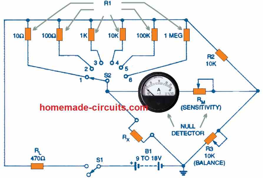
Figure 6 above depicts a contemporary six-range variation of this circuit, with Table 2 listing its advantages over the circuit depicted in Figure 3. Its null sensitivity (which is equivalent to the ratio of R3/R2 at balance) is extremely high across the board, ranging from 0.003 percent at full scale to 0.03 percent at 1/10th of full scale.
All resistance values in the 1-ohm to 1M range can be measured with high null sensitivity by restricting all readings to the upper 9/10th of the R3 range. The basic working principles of a Wheatstone bridge's are unaffected by whether it is powered by an AC or DC supply.
The balanced state of an AC powered Wheatstone bridge is preserved by an infinitely adjustable set of "ratio" arms comprising of potentiometer R1 that generates the resistive values of R1 and R2. The potential difference value delivered by the potentiometer is equal to the total of the resistive values of R1 and R2.
Using Headphones
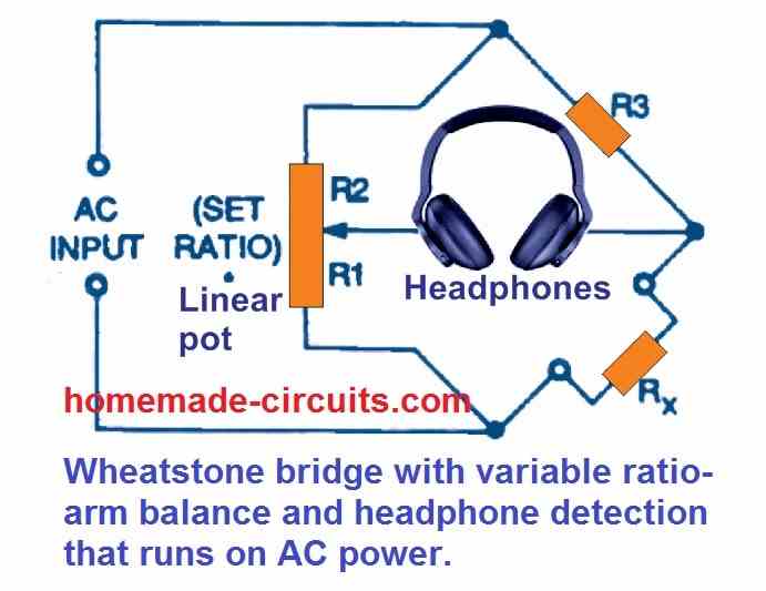
This circuit's balancing sensitivity is strong enough to allow detection using earphones. The Wheatstone bridge circuit of Figure 7 above, is shown in Figure 8 below using a five-range equivalent. It has the best accuracy level between 10 ohms and 10 megohms and spans a resistance range between an almost zero ohms and near infinite ohms.
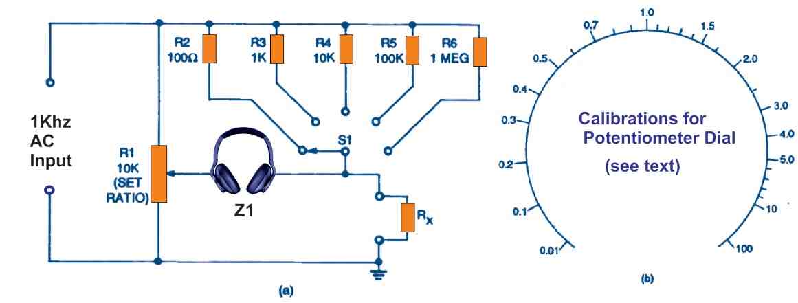
When the wiper on the rotary panel potentiometer R1 is rotated at midway, its resistive ratio equals one. In order to calibrate this control potentiometer, the following figure illustrates a standard scale graduation. These graduations must be tagged physically, as explained later in this page.
In the Fig.8 circuit, hook up the bridge to a 1-kHz sinewave generator, connect the unknown resistor Rx, and tweak the rotary switch S1 and rotary panel potentiometer R1 until a null point is heard on the headphones.
As soon as this happens, the value of resistor Rx becomes equal to the value of the resistor attached to S1 multiplied by the potentiometer R1's scale value.
A balance could be achieved across any range, however for the best accuracy, the reading of the R1 scale should be between 0.27 and 3.0.
Add a 10-kilohm, 1% resistor in the Rx slot in order to calibrate the scale of the panel potentiometer R1. Next, gradually index rotary switch S1 via its 100-ohm, 1-kilohm, 10-kilohm, 100-kilohm, and 1-megohm settings. On every consecutive balancing point, print 0.01, 0.1, 1.0 (mid-scale), 10, and 100 on the scale.
Repeat this step with Rx values which are multiples or submultiples of 1.5, 2, 3, 4, 5, and so on, until the scale is fully calibrated, as illustrated in Fig. 8-b.
Accuracy and Resolution
A measuring bridge may include four critical performance parameters: (1) measuring range, (2) balance sensitivity, (3) resolution, and (4) accuracy. The precision through which the Rx value could be determined from the bridge's controls is referred to as resolution.
In Figs. 3 and 6, for instance, R3 has a resolution of roughly 1% of full-scale in case it is calibrated by hand, or through linear potentiometer. The resolution can be about 0.005% of full-scale if it incorporates a four-decade resistor box. The resolution of the bridge in Fig. 8 ranges from 1% at a "1" ratio to 2% at a 0.3 or 3.0 ratio and 5% at a 0.1 or 1.0 ratio.
The word precision indicates the bridge circuit's inherent accuracy, considering it has an ideal balance, sensitivity, resolution, and is equivalent to the the sum of the R1 /R2 ratio tolerance and the resistance standard R3 tolerance.
When highly precise resistors are used to generate the R1/R2 ratio, the accuracy of the ratio matches the total of the R1 and R2 tolerances. Alternative approaches, on the other hand, allow resistors to be adjusted such that ratio inaccuracies are minimized to less than 0.005%. For instance, if R1 and R2 are 1 percent resistors, and R3 is a hand calibrated control potentiometer, the high-resolution Wheatstone bridge in Fig. 6 has a fundamental accuracy of just 3 percent.
The accuracy of the bridge improves to 1.005 percent in case the values of R1 and R2 are perfectly paired. With a 0.1 percent multidecade resistor box in the R3 slot, the circuit's accuracy may be enhanced to 0.105 percent.
While measuring extremely low or extremely high resistance levels, remember that unexpected inaccuracies could emerge. While evaluating low resistive values, the most probable reason will be the resistance values of switch contacts and connections, whereas while measuring high resistive values, leakages could be the primary culprit.
A bridge's ultimate quality is determined by its balance, which includes sensitivity, resolution, and accuracy. As a conclusion, the circuit in Fig. 6 can exhibit great sensitivity, resolution, and accuracy. Thus, depending on how it is designed, it may serve as the fundamental circuit of either an affordable, straightforward bench measuring device or an unit inside a sophisticated laboratory equipment.
On the contrary, the bridge circuit in Fig. 8 above may exhibit a lower resolution and accuracy by design. This implies that this may be only good for quick, approximate readings, such as those essential for servicing equipment.
How to Measure Component Values
Reactance, resistance, capacitance (C), and inductance could all be measured using an AC-powered Wheatstone bridge (L). The circuit in Figure 9 shown below is a version of the circuit in Figure 7 that measures C or L values by substituting equivalent reactances for R4 and Rx. This should work when Cx and Lx are nice and clean and have 1 kHz impedances of lower than 10 M and larger than roughly 1 ohm.
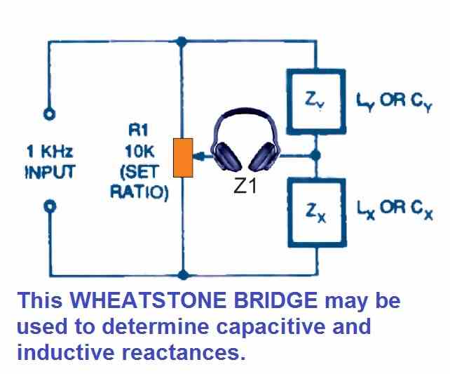
The challenge in using this circuit to determine inductance is that perfect inductors (to be used in the Z4 slot) are difficult to obtain, and inductive impedances at 1 kHz are hardly 6.28 ohms / millihenry.
The main problem with evaluating capacitance is that the Cx value is equivalent to the reciprocal of the resistance scale marks on the potentiometer R1. A couple of calibrated pairs of potentiometer R1 scales are required in case the standard bridge is to measure both R and C.
This flaw could be solved by installing an inverting switch on R1. The multi-range LCR bridge in Figure 10 is an illustration of this. As a result, there is just one scale, as indicated in Fig. 8.
The below indicated Fig. 10 universal LCR bridge with headphone detector is a multifunctional device. It may be implemented with either internal or external L, C, or R specifications due to the switch S2.
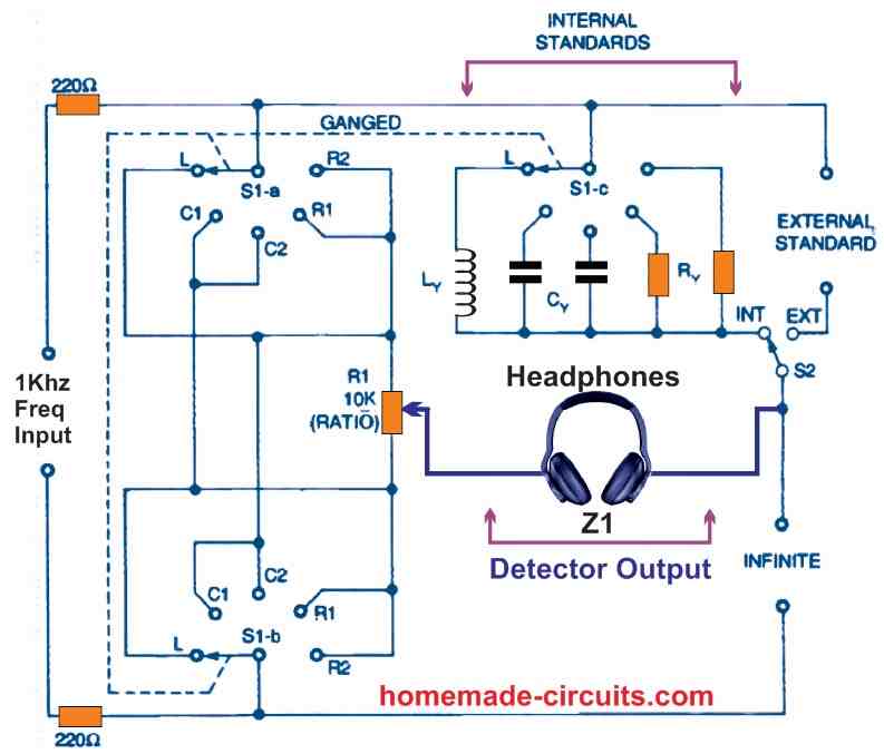
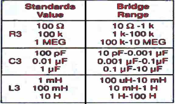
As shown in Table 3 below, the value of each range at the center of the scale will be equal to the value of the standard component allocated to that range.
Once calibrated, this equipment can facilitate the creation of its own alternative measuring standards. As an illustration, if a 10-nanofarad capacitance standard is connected on the the EXTERNMAL STANDARD ports, a 100-nanofarad standard may be constructed by setting potentiometer R1 to "10" and attaching capacitors in parallel over the "X" terminal and a null balance could be achieved.
The Cx value becomes approximately 100 nanofarads when this happens. The bridge may subsequently be linked to the 100 nanofarad standard to generate a 1 microfarad standard.
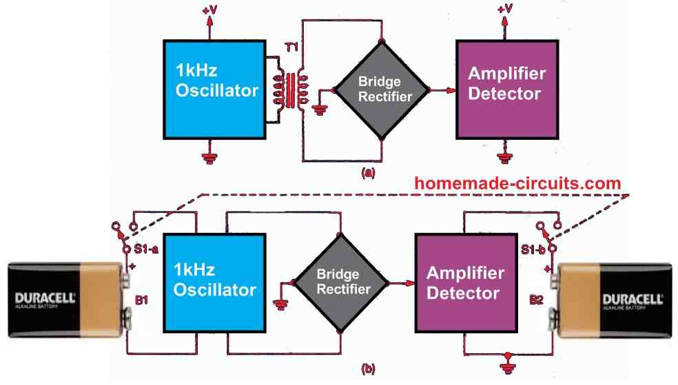
Figure 11 above depicts two different flowchart. The first alternative, shown in Figure 11a, is to power the two circuits from the same source while isolating the oscillator by coupling its output to the bridge through a transformer. The oscillator can also be powered by its own "floating" source, as shown in Fig. 11 -b. This second alternative is the most practical.
The concept for a battery-powered bridge power source is shown in Figure 12 below.
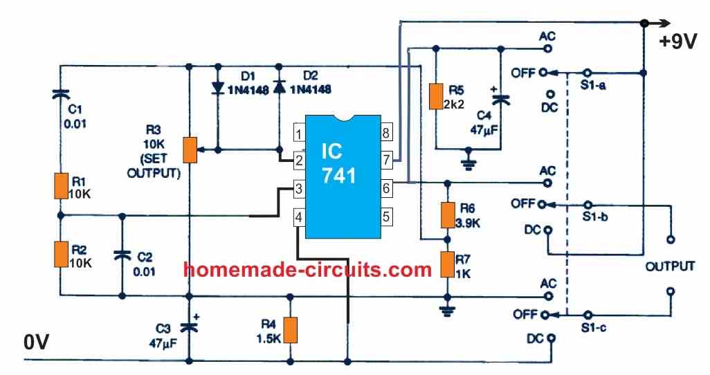
It may generate a 9-volt DC signal or a high-quality 1-kHz sinewave signal with a peak-to-peak magnitude of 5 volts. The oscillator is actually a Wien bridge oscillator stabilised using diodes that draws power from the battery via resistors R1 and R2. The circuit features a low-impedance output with a quiescent current of lower than 4 milliamperes. In order to configure the oscillator's output to a good oscilloscope, adjust potentiometer R1 to get a relatively pure sinewave output of roughly 5 volts peak-to-peak.