A wireless cellphone battery charger is a device that charges a compatible cellphone or mobile phone placed close to it, through high frequency wireless current transfer, without any physical contact.
In this post I have explained how to build a wireless cellphone battery charger circuit for facilitating a cordless cellphone charging without employing a conventional charger.
The Objective
Here the cellphone is required to be installed with a receiver circuit module internally and connected to the charging socket pins, for implementing the wireless charging process.Once this is done, the cellphone simply needs to be kept over the wireless charger unit for initiating the proposed wireless charging.
In one of our earlier posts I have explained a similar concept which explained the charging of a Li-ion battery through a wireless mode, here too we employ a similar technique but try to implement the same without removing the battery from the cellphone.
Also, in our previous post I will comprehensively explained the basics of wireless charging, we'll take the help of the instructions presented there and try to design the proposed wireless cellphone charger circuit.
We'll begin with the power transmitter circuit which is the base unit and is supposed to be attached with the mains supply and for radiating the power to the cellphone module.
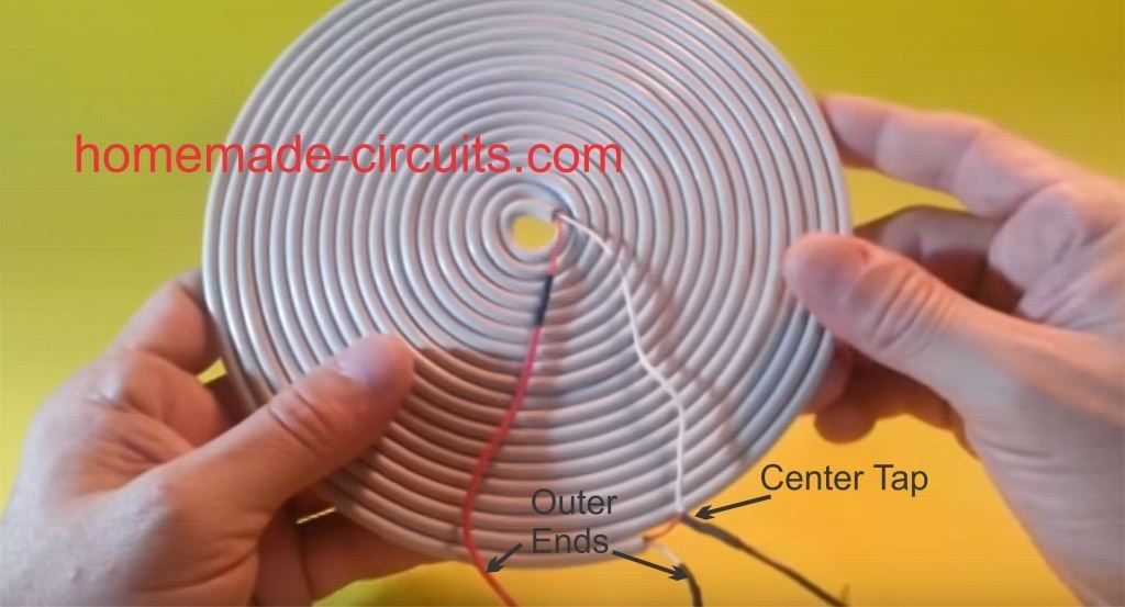
The Transmitter (Tx) Coil Specifications:
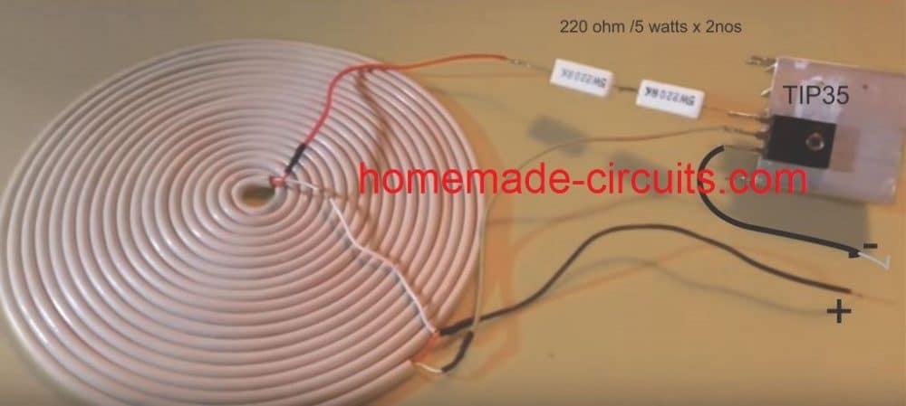
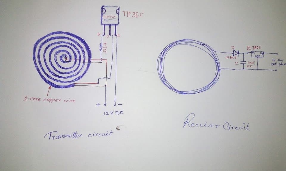
The transmitter circuit for this wireless cellphone battery charger is the crucial stage and must be built accurately, and it must be structured as per the popular Tesla's pancake coil arrangement as shown below:

Making a PCB version of the above Pancake coil.
Inspired from the above theory, the smaller layout of the same coil can be etched over a PCB as shown in the following diagram, and wired as indicated:
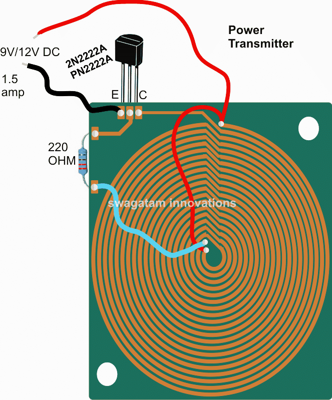
Dimensions: 10 inches by 10 inches, bigger size might enable faster charging and better current output
The figure above shows the power emitter or radiator design, also recall the circuit diagram from our previous post, the above design utilizes exactly the same circuit layout, although here we do it through a PCB by etching the winding layout over it.
A careful observation shows that the above layout has a pair of parallel coiled copper tracks running spirally, and forming the two halves of the transmitter coil, wherein the center tap is acquired with the aid of the linked red jumper wire across the ends of the coils.
The layout allows the design to be compact and effective for the required operations.
The track layout could be in the form of a square, or oval on one side and squarish on the other in order to make the unit even sleeker.
Rest of the portion is quite straightforward and is as per our earlier diagram, where the transistor is 2N2222 included for inducing the required high frequency oscillations and propagation.
The circuit is operated from a 12V/1.5 amp source, and the number of turns (coils) may selected approximately in accordance with the supply voltage value, that is around 15 to 20 turns for each halves of the transmitter coil. Higher turns will result in lower current and boosted voltage radiations and vice versa
When switched ON, the circuit may be expected to generate a strong magnetic flux around the coiled tracked, equivalent to the input power.
Now the radiated power needs to be absorbed using an identical circuit for executing the wireless power transfer and the intended cell phone charging.
For this we need a power collector or receiver circuit for collecting the radiated power, this may be devised as explained in the following section:
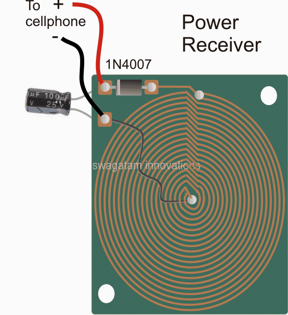
Dimension: 3 inches by 3 inches or as per the accommodation space available inside your cellphone
As may be witnessed in the above receiver design, an identical layout of the coil may seen, except that here the two concentric spirals are connected in parallel to add current in contrast to the transmitter layout which incorporated a series connection owing to the center tap restriction for the design.
The design is supposed to be small enough to fit inside a standard cellphone, just below the hind cover, and the output which is terminated through a diode may be connected either with the battery directly or across the charging socket pins (internally).
Once the above mobile battery charger circuits are built, the transmitter circuit may be connected with the indicated DC input, and the receiver module placed right over the transmitter board, at the center.
An LED with a 1k resistor could be included at the output of the receiver circuit in order to get a instant indication of the wireless power conduction process.
After the operation is confirmed, the output from the receiver may be connected to the socket of the cell phone for checking the response of the wireless charging effect.
However before this you may want to confirm the output to the cellphone from the wireless receiver module...it should be around 5 to 6V, if it's more, the black wire could be simply shifted and soldered a few coils towards the top until the right voltage is achieved.
Once all the confirmation are complete the module could be accommodated inside a cellphone and the connections done appropriately.
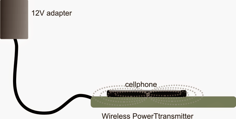
Finally, hopefully if everything is done correctly the assembly might allow you to keep the cellphone directly over the transmitter set up and enable the proposed wireless cellphone charging to happen successfully.
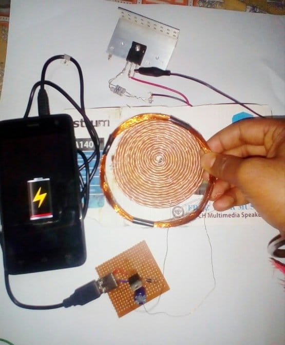
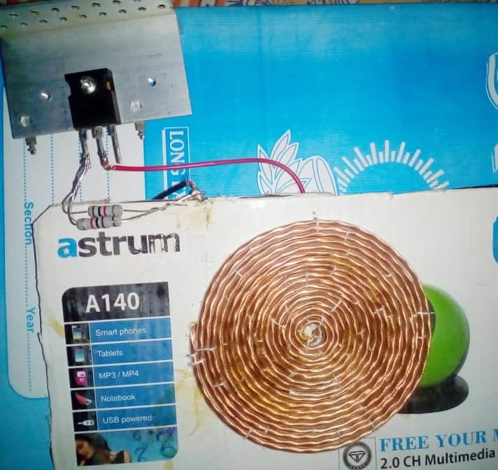
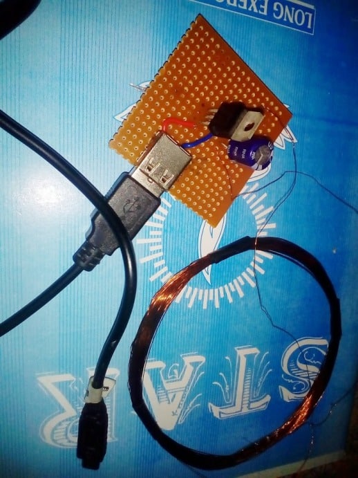
Making a Practical Prototype
The above wireless power transfer concept was successfully tried and tested with some modifications, by Mr. Narottam Gupta who is an an avid follower of this blog.
The modified wireless cellphone charger circuit and the prototype images can be witnessed below: