In this post I will show how to construct wireless office calling bell which can be used for calling 6 different personnel from head’s / boss’s desk or some other calling bell type fun project for your home.
Using nRF24L01 2.4 GHz module
We will be constructing a simple wireless calling bell using Arduino and nRF24L01 2.4 GHz module, which can work around your home or your office without any hiccups or coverage issue.
The proposed circuit can be powered from a 5V smartphone adapter or any inexpensive 5V adapter which keeps your circuit alive and ready to hear your call.
Let’s look an overview of nRF24L01 2.4 GHz module.
Technical Datasheet
The nRF24L01 is a 2.4 GHz transceiver module for wireless communication.
Main Specifications:
Operating Voltage: 1.9V to 3.6V (use 3.3V for Arduino).
Current Consumption:
- Transmit (TX) Mode: 11.3 mA at 0 dBm power.
- Receive (RX) Mode: 12.3 mA.
- Power-Down Mode: 900 nA.
- Data Rate: Up to 2 Mbps.
- Output Power: Configurable from -18 dBm to 0 dBm.
Power Requirements
Voltage: You must use a stable 3.3V supply. A 10 µF capacitor between VCC and GND near the module is recommended to filter voltage spikes.
SPI Communication Timing
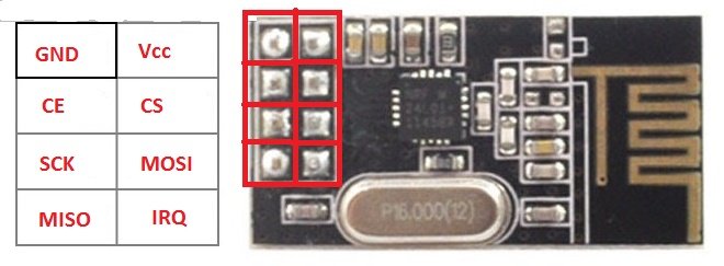
The module communicates using SPI with the following connections:
- CE: Connect to Arduino digital pin 9.
- CSN: Connect to Arduino digital pin 10.
- SCK: Connect to Arduino digital pin 13.
- MOSI: Connect to Arduino digital pin 11.
- MISO: Connect to Arduino digital pin 12.
The SPI clock speed can go up to 10 MHz.
Transmission Range Calculation
The range depends on the power, the antenna, and the environment.
Free-Space Range Formula:
Maximum Range ≈ √(Pt × Gt × Gr / ((4 × π × f)² × S))
Where:
- Pt = Transmit power in watts.
- Gt = Transmit antenna gain (default: 1).
- Gr = Receive antenna gain (default: 1).
- f = Frequency in Hz (2.4 GHz = 2.4 × 10⁹ Hz).
- S = Receiver sensitivity in watts (-85 dBm = 3.16 × 10⁻⁹ W).
Example Calculation:
For Pt = 0.001 W, f = 2.4 * 109 Hz, and S = 3.16 * 10-9 W:
Maximum Range ≈ √(0.001 * 1 * 1 / ((4 * π * 2.4 * 109)² * 3.16 * 10-9)).
Simplifying to estimate the range.
Data Rate and Power Consumption
In case you are using higher data rates (e.g. 2 Mbps) then it will consume more power but reduce communication time. Lower transmit power levels (-6 dBm, -12 dBm, -18 dBm) save energy but reduce range.
Current Consumption Calculation
Transmit Power Consumption:
Power = Voltage × Current
For TX at 0 dBm, Current = 11.3 mA = 0.0113 A
Power = 3.3 × 0.0113 = 0.03729 W
Receive Power Consumption:
For RX, Current = 12.3 mA = 0.0123 A
Power = 3.3 × 0.0123 = 0.04059 W
Interference and Channel Selection
The module operates on the 2.4 GHz band, shared with Wi-Fi and Bluetooth.
You can Use non-overlapping channels (e.g. 1 to 125) to minimize interference.
Packet Handling
The module supports:
Payload Size: 1 to 32 bytes.
Address Width: 3 to 5 bytes for unique device identification.
CRC Check: 1 or 2 bytes for error detection.

Detailed Description
The above chip is called nRF24L01 module. It is a duplex (bi-directional) communication circuit board designed for microcontrollers and single board computers like Raspberry Pi.
It utilizes 2.4 GHz frequency which is ISM band (Industrial, Scientific and Medical band) it is the same frequency used in Wi-Fi communication.
It can transmit or receive data at the rate of 2Mbps, but in this project the transmission and reception is limited to 250 Kbps because of lower data requirements and lowering the data rate will results in increased overall range.
It consumes only 12.3 mA at peak data transmission which makes battery friendly device. It utilizes SPI protocol for communicating with microcontroller.
It has transmission / reception range of 100 meter with no obstacle in between and about 30 meter range with some obstacle.
You can find this module on popular e-commerce sites, also at your local electronics store.
Note: The module can work from 1.9 to 3.6V, the on board regulator on the Arduino can provide 3.3V for the module. If you connect the nRF24L01’s Vcc terminal to 5V of Arduino’s output, this will result in malfunction of the module. So care must be taken.
That’s the brief introduction to the nRF24L01 module.
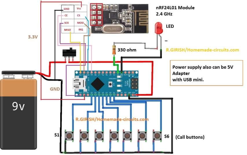
Let’s investigate the details of the circuit diagram:
The Remote Control Circuit:
Remote will be with the boss or the head of the office.

The remote consists of Arduino nano; by the way you can use any Arduino board, 6 push buttons for ringing six different receivers, nRF24L01 module and a LED for acknowledging the push of a button.
You can power this using 9V battery or from 5V adapter. In case of battery you should turn off this remote after your call.
Now let’s look at the code. Before that you need to download the library file only then the code gets compiled.
Link: github.com/nRF24/RF24.git
Code for Remote:
// --------- Program Developed by R.GIRISH / homemade-circuits. com -------//

#include <RF24.h>

#include<SPI.h>

RF24 radio(9, 10);

const byte address_1[6] = "00001";

const byte address_2[6] = "00002";

const byte address_3[6] = "00003";

const byte address_4[6] = "00004";

const byte address_5[6] = "00005";

const byte address_6[6] = "00006";

const int input_1 = A0;

const int input_2 = A1;

const int input_3 = A2;

const int input_4 = A3;

const int input_5 = A4;

const int input_6 = A5;

const int LED = 2;

const char text[] = "call";

void setup()

{

pinMode(input_1, INPUT);

pinMode(input_2, INPUT);

pinMode(input_3, INPUT);

pinMode(input_4, INPUT);

pinMode(input_5, INPUT);

pinMode(input_6, INPUT);

pinMode(LED, OUTPUT);

digitalWrite(input_1, HIGH);

digitalWrite(input_2, HIGH);

digitalWrite(input_3, HIGH);

digitalWrite(input_4, HIGH);

digitalWrite(input_5, HIGH);

digitalWrite(input_6, HIGH);

radio.begin();

radio.setChannel(100);

radio.setDataRate(RF24_250KBPS);

radio.setPALevel(RF24_PA_MAX);

radio.stopListening();

}

void loop()

{

if (digitalRead(input_1) == LOW)

{

radio.openWritingPipe(address_1);

radio.write(&text, sizeof(text));

digitalWrite(LED, HIGH);

delay(400);

digitalWrite(LED, LOW);

}

if (digitalRead(input_2) == LOW)

{

radio.openWritingPipe(address_2);

radio.write(&text, sizeof(text));

digitalWrite(LED, HIGH);

delay(400);

digitalWrite(LED, LOW);

}

if (digitalRead(input_3) == LOW)

{

radio.openWritingPipe(address_3);

radio.write(&text, sizeof(text));

digitalWrite(LED, HIGH);

delay(400);

digitalWrite(LED, LOW);

}

if (digitalRead(input_4) == LOW)

{

radio.openWritingPipe(address_4);

radio.write(&text, sizeof(text));

digitalWrite(LED, HIGH);

delay(400);

digitalWrite(LED, LOW);

}

if (digitalRead(input_5) == LOW)

{

radio.openWritingPipe(address_5);

radio.write(&text, sizeof(text));

digitalWrite(LED, HIGH);

delay(400);

digitalWrite(LED, LOW);

}

if (digitalRead(input_6) == LOW)

{

radio.openWritingPipe(address_6);

radio.write(&text, sizeof(text));

digitalWrite(LED, HIGH);

delay(400);

digitalWrite(LED, LOW);

}

}

// --------- Program Developed by R.GIRISH / homemade-circuits. com -------//
That concludes the remote / transmitter.
Now let’s look at the receiver.
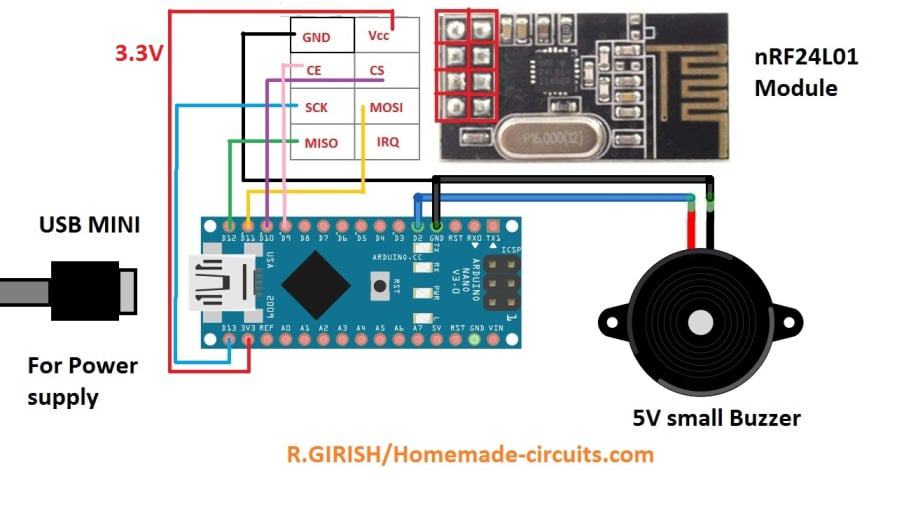
The Receiver Circuit:
NOTE: You can make one receiver or six receivers depending on your needs.
The receiver consists of Arduino board, nRF24L01 module and a buzzer. Unlike the remote, receiver should be powered from 5V adapter, so that you don’t depend on the batteries which will drain within couple of days.

Now let’s look at the code for receiver:
Program Code for the Receiver
// --------- Program Developed by R.GIRISH / homemade-circuits. com -------//

#include <RF24.h>

#include<SPI.h>

RF24 radio(9, 10);

const int buzzer = 2;

char text[32] = "";

// ------- Change this ------- //

const byte address[6] = "00001";

// ------------- ------------ //

void setup()

{

Serial.begin(9600);

pinMode(buzzer, OUTPUT);

radio.begin();

radio.openReadingPipe(0, address);

radio.setChannel(100);

radio.setDataRate(RF24_250KBPS);

radio.setPALevel(RF24_PA_MAX);

radio.startListening();

}

void loop()

{

if (radio.available())

{

radio.read(&text, sizeof(text));

digitalWrite(buzzer, HIGH);

delay(1000);

digitalWrite(buzzer, LOW);

}

}

// --------- Program Developed by R.GIRISH / homemade-circuits. com -------//
NOTE:
If you are going to build more than one receiver for this office call bell system, then you should change the mentioned value on successive receiver build and upload the code.
For the first receiver (no need to change anything):
// ------- Change this ------- //
const byte address[6] = "00001"; and upload the code.
// ------------- ------------ //
For the second receiver (You have to change):
const byte address[6] = "00002"; and upload the code.
For the third receiver (You have to change):
const byte address[6] = "00003"; and upload the code.
And so on…….. up to “00006” or the sixth receiver.
When you press “S1” on the remote, the receiver with address “00001” will respond / buzz.
When you press “S2” on the remote, the receiver with address “00002” will respond / buzz.
And so on……
That concludes the receiver circuit details.
If you have more questions, please feel free to express them in the comment section, we will try to get back to you soon with a reply