Zener diodes - named after its inventor Dr. Carl Zener are fundamentally used in electronic circuits for generating precise voltage references. These are devices that are able to create a practically constant voltage across them regardless of variations in circuit and voltage situations.
Externally, you may find zener diodes a lot similar to standard diodes such as 1N4148. Zener diodes also work by rectifying AC into pulsating DC quite like their traditional alternatives. However contrary to standard rectifier diodes, zener diodes are configured with their cathode directly connected with the positive of the supply, and anode with the negative supply.
Characteristics and Working
In its standard configuration, Zener diodes exhibit a high resistance below a particular, critical, voltage (known as the Zerier voltage). When this specific critical voltage is surpassed, the active resistance of Zener diode falls to an extremely low level.
And at this low resistance value, an effective constant voltage is held across the Zeners, and this constant voltage can be expected to retain regardless of any change in the source current.
In simple words, whenever the supply across the zener diode exceeds the rated zener value, the zener diode conducts and grounds the excess voltage. Due to this the voltage drops below the zener voltage which switches OFF the zener, and the supply yet again tries to exceed the zener voltage, switching ON the zener yet again. This cycle repeats rapidly which ultimately results in stabilizing the output to exactly at a constant zener voltage value.
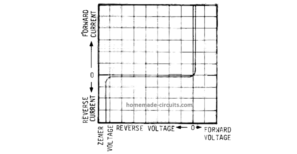
This characteristic is graphically highlighted in the below figure which indicates that above the 'Zener voltage' the reverse voltage continues to be almost constant even with variations in reverse current. As a result Zener diodes are often used for getting a constant voltage drop, or reference voltage, with their internal resistance.
Zener diodes are designed in many wattage ratings and with voltage ratings which range from 2.7 Volts to 200 Volts. (However mostly , Zener diodes with values far above 30 Volts are hardly ever used.)
How to Select Zener Diode Resistor (Learn More)
A standard voltage regulator circuit, using a single resistor and a Zener diode, can be witnessed in the following image. Here, let's assume the value of the Zener diode is 4.7 V and the supply voltage V in is 8.0 V.
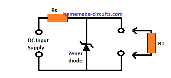
The basic working of a zener diode can be explained with the following points:
In an absence of a load across the output of the zener diode, a 4.7 Volts can be seen dropped across the Zener diode while a cut off 2.4 Volts is developed across resistor Rs.
Now, in case the input voltage is altered, let's imagine, from 8.0 to 9.0 V, will cause the voltage drop across the Zener to still maintain the rated 4.7 V.
However the voltage drop across the resistor Rs could be seen raised, from 2.4 V, to 3.4 V.
The voltage drop across an ideal Zener can be expected to be pretty constant. Practically , you may find the voltage across the zener increasing slightly because of the dynamic resistance of the Zener.
The procedure through which the change in Zener voltage is calculated is by multiplying the zener dynamic resistance with the change in Zener current.
The resistor R1, in the above basic regulator design, symbolizes the preferred load that may be connected with the zener. R1 in this connection will draw certain amount of current which was moving through the Zener.
Since the current in Rs will be higher than the current entering the load, an amount of current will continue to go through the Zener enabling a perfectly constant voltage across the Zener and the load.
The indicated series resistor Rs should be determined in such a way that the lowest current entering the Zener is always higher than the minimum level specified for a stable regulation from the zener. This level starts just under the 'knee' of the reverse voltage/reverse current curve as learned from the previous graphical diagram above.
You must additionally make sure that the selection of Rs ensures that current passing through the Zener diode never goes beyond its power rating: which may be equivalent to the Zener voltage x Zener current. It is the highest amount of current that may pass through the Zener diode in the absence of the load R1.
How to Calculate Zener Diodes
Designing a basic zener circuit is actually simple and can be implemented through the following instructions:
- Determine the maximum and minimum load current (Li), for example 10 mA and 0 mA.
- Determine the maximum supply voltage that may develop, for example a 12 V level, also ensuring that the minimum supply voltage is always = 1.5 V + Vz (the zener voltage rating).
- As indicated in the basic regulator design the required output voltage which is the equivalent Zener voltage Vz = 4.7 Volts, and the selected lowest Zener current is 100 microamps. This implies that the maximum intended Zener current here is 100 microamps plus 10 milliamps, which is 10.1 milliamps.
- The series resistor Rs must allow the minimum amount of current 10.1 mA even when the input supply is a the lowest specified level, which is 1.5 V higher than the selected zener value Vz, and may be calculated using Ohms law as: Rs = 1.5 / 10.1 x 10-3 = 148.5 Ohms. The closest standard value seems to be 150 Ohm, so Rs may be 150 ohms.
- If the supply voltage rises to 12 V, the voltage drop across Rs will be Iz x Rs, where Iz = current through the zener. Therefore, applying Ohm's law we get Iz = 12 - 4.7 / 150 = 48.66 mA
- The above is the maximum current that will be allowed to pass through the zener diode. In other words, the maximum current that may flow during maximum output load or maximum specified supply voltage input. Under these conditions, the zener diode will dissipate a power of Iz x Vz = 48.66 x 4.7 = 228 mW. The closest standard power rating value to fulfill this is 400 mW.
Effect of Temperature on Zener Diodes
Along with voltage and load parameters, Zener diodes are also quite resistant to temperature variations around them. However, above an extent the temperature may have some affect on the device as indicated in the graph below:
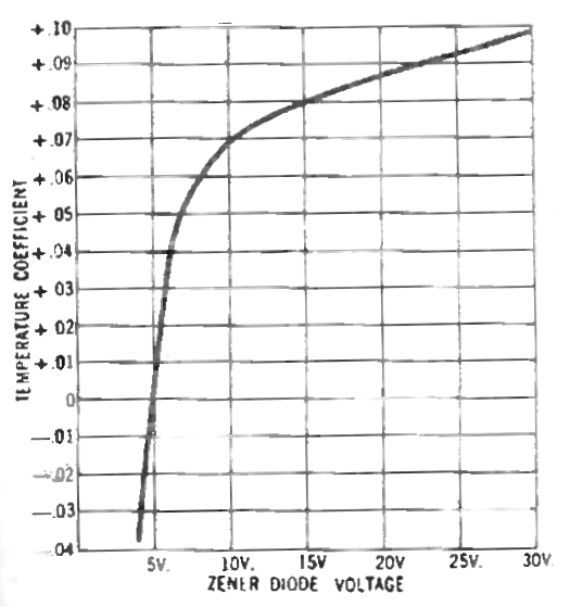
It shows the zener diode temperature coefficient curve. Although at higher voltages the coefficient curve responds at around 0.1% per degree Celsius, it moves through zero at 5 V and then turns negative for the lower voltage levels. Eventually it reaches -0.04% per degree Celsius at around 3.5 V.
Using Zener Diode as Temperature Sensor
One good use of the Zener diode's sensitivity to temperature change is to apply the device as a temperature sensor device as shown in the following diagram
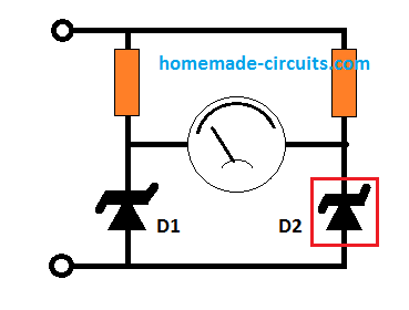
The diagram shows a bridge network built using a pair of resistors and a pair of Zener diodes having identical characteristics. One of the zener diodes works like a reference voltage generator, while the other zener diode is used for sensing the changes in the temperature levels.
A standard 10 V Zener may have a temperature coefficient of +0.07%/ °C which may correspond to 7 mV/ °C variation in temperature. This will create an imbalance of around 7 mV between the two arms of the bridge for every single degree Celsius variation in the temperature. A 50 mV full FSD meter can be used in the indicated position for showing the corresponding temperature readings.
Customizing Zener Diode Value
For some circuit application it may be necessary to have a precise zener value which may be a non-standard value, or a value not readily available.
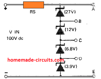
For such cases an array of zener diodes can be created which may then be used for getting a desired customized zener diode value, as shown below:
In this example, many customized, non standard zener values could be acquired across the various terminals, as described in the following list:
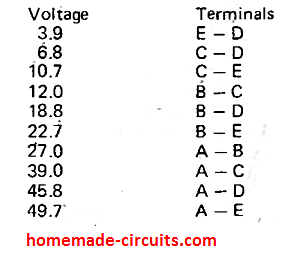
You can use other values in the indicated positions to get many other customized sets of zener diode output
Zener Diodes with AC Supply
Zeners diodes are normally used with DC supplies, however these devices can be also designed to work with AC supplies. A few AC applications of zener diodes include audio, RF circuits, and other forms of AC control systems.
As shown in the below example when an AC supply is used with a zener diode, the zener will instantly conduct as soon as the AC signal passes from zero towards the negative half of its cycle. Because, the signal is negative therefore the AC will be shorted via the anode to cathode of the zener, causing 0 V to appear the output.
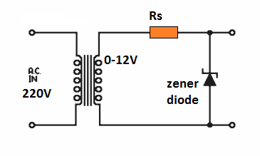
When the AC supply moves across the positive half of the cycle, the zener doesn't conduct until the AC climbs up to the zener voltage level. When the AC signal crosses the zener voltage, the zener conducts and stabilizes the output to a 4.7 V level, until the AC cycle drops back to zero.
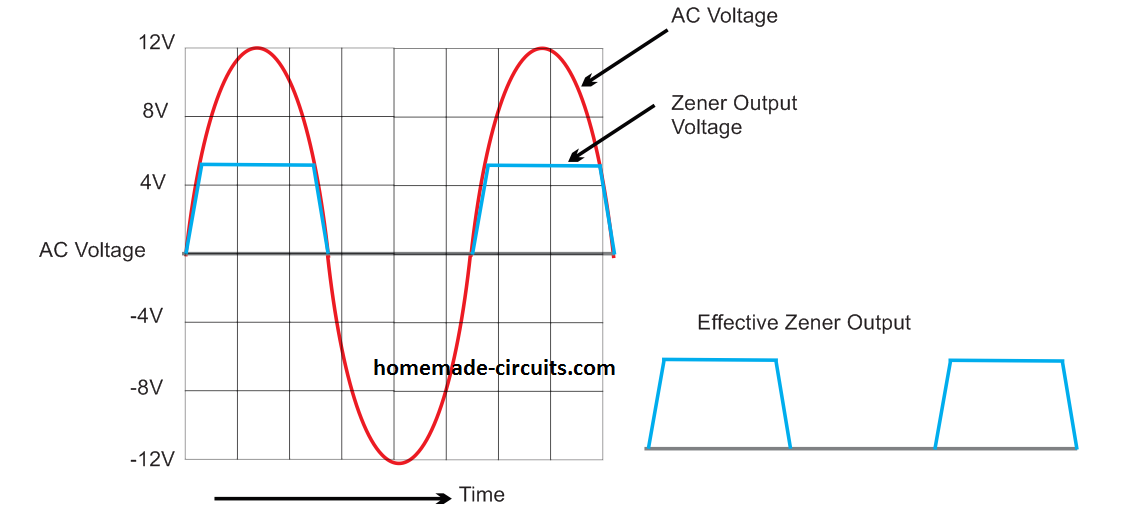
Remember, while using zener with an AC input, makes sure that Rs is calculated as per the AC peak voltage.
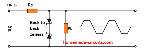
In the above example, the output is not symmetrical, rather a pulsating 4.7 V DC. In order to get a symmetrical 4.7 V AC at the output, two back to back zeners could be connected as depicted in the below diagram
Suppressing Zener Diode Noise
Although zener diodes provide a quick and easy way to create stabilized fixed voltage outputs, it has one drawback which may affect sensitive audio circuits such as power amplifiers.
Zener diodes generate noise while operating due to their junction avalanche effect while switching, ranging from 10 uV to 1 mV. This can be suppressed by adding a capacitor in parallel with the zener diode, as shown below:
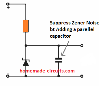
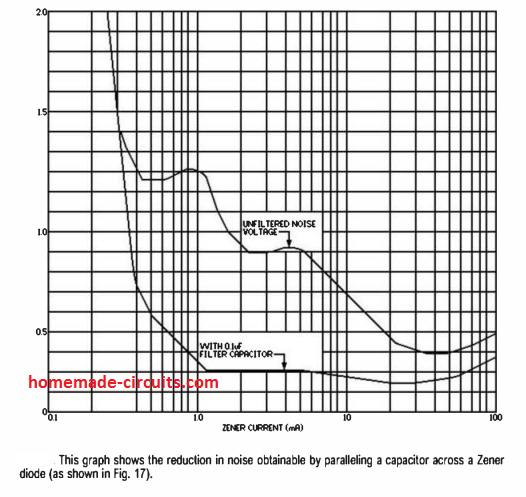
The value of the capacitor can be between 0.01uF and 0.1uF, which will allow noise suppression by a factor of 10, and will maintain the best possible voltage stabilization.
The following graph shows the effect of the capacitor for reducing zener diode noise.
Using Zener for Ripple Voltage Filtering
Zener diodes can be also applied as effective ripple voltage filters, just as it's used for AC voltage stabilization.
Due to its extremely low dynamic impedance, zener diodes are able to work like ripple filter quite the same way as filter capacitor do.
Very impressive ripple filtering can be obtained by connecting a Zener diode across the load, with any DC source. Here, the voltage must be same as the ripple trough level.
In most circuit applications this may work as effectively as a typical smoothing capacitor having several thousand microfarads capacity, resulting in a significant reduction in the level of ripple voltage superimposed on the DC output.
How to Increase Zener Diode Power Handling Capacity
An easy way to increase zener diode power handling capacity is probably to just connect them in parallel as shown below:
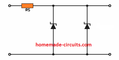
However, practically this may not be as simple as it looks and may not work as intended. This is because just like any other semiconductor device, zeners also never come with exactly identical characteristics, therefore one of the zeners may conduct before the other drawing the entire current through itself, eventually getting destroyed.
A quick way to counter this problem may be to add low values series resistors with each zener diodes as shown below, which will allow each zener diode to share the current uniformly through compensating voltage drops generated by the resistors R1 and R2:
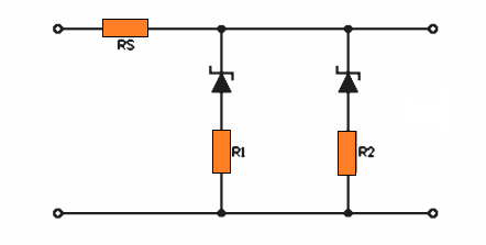
Although, the power handling capacity can be increased by connecting Zener diodes in parallel, a much improved approach may be to add a shunt BJT in conjunction with a zener diode configured as a reference source. Please see the following example schematic for the same.
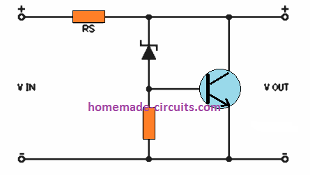
Adding a shunt transistor not only enhances the zener power handling capacity by a factor of 10, it further improves the voltage regulation level of the output, which may be as high as the specified current gain of the transistor.
This type of shunt transistor zener regulator can be used for experimental purposes because the circuit features a 100% short circuit proof facility. That said, the design is rather inefficient because the transistor may dissipate a significant amount of current in the absence of a load.
For even better results, a series pass transistor type of regulator as shown below looks a better option and preferable.
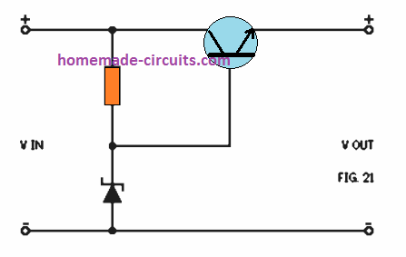
In this circuit the Zener diode creates a reference voltage for the series pass transistor, which, essentially, works like an emitter follower. As a result the emitter voltage is maintained between a few tenths of a volt of the transistor base voltage as created by the Zener diode. Consequently the transistor works like a series component and enables effective control of the supply voltage variations.
The entire load current now runs via this series transistor. The power handling capacity of this type of configuration is established totally by the value and the specification of the transistors, and also depends on the efficiency and quality of the heatsink used.
Excellent regulation could be achieved from the above design using a 1k series resistor. The regulation could be increased with a factor of 10 by replacing the normal zener with a special low dynamic zener diode such as a 1N1589).
In case you want the above circuit to provide a variable voltage regulated output, it could be easily achieved by using a 1K potentiometer across the Zener diode. This allows a variable reference voltage to be adjusted at the base of the series transistor.
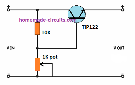
However, this modification may result in a lower regulation efficiency due to some shunting effect created by the potentiometer.
Constant Current Zener Diode Circuit
A simple Zener-regulated constant current supply can be designed through a single transistor as a variable series resistor. The figure below demonstrates the basic circuit diagram.
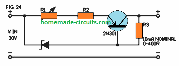
You can see a couples of circuit passages here, one via the zener diode connected in series with the biasing resistor, while the other path is through the resistors R1, R2, and the series transistor.
In case the current deviates from its original range, it creates a proportionate change in the biasing level of R3, which in turn causes the series transistor resistance to increase or decrease proportionately.
This adjustment in the resistance of the transistor results in an automatic correction of the output current to the desired level. The accuracy of the current control in this design will be around +/- 10% in response to an output conditions that may range between a short circuit and a loading of up to 400 Ohm.
Sequential Relay Switching Circuit using Zener Diode
If you have an application where a set of relays are required to be switched sequentially one after the other on power switch instead of all activating together, then the following design can prove quite handy.
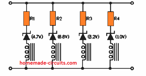
Here, sequentially incrementing zener diodes are installed in series with a group of relays along with individual low value series resistors. When power is switched ON, the zener diodes conduct one after the other in sequence in an increasing order of their zener values. This results in the relay switching ON in sequence as desired by the application. The values of the resistors can be 10 ohms or 20 ohms depending on the resistance value of the relay coil.
Zener Diode Circuit for Over Voltage Protection
Due to their voltage sensitive characteristic, it is possible to combine Zener diodes with the current sensitive characteristic of fuses for safeguarding crucial circuit components from high voltage surges, and additionally eliminating the hassle of fuse from blowing frequently, which may happen especially when a fuse rating is very near to the operating current spec of the circuit.
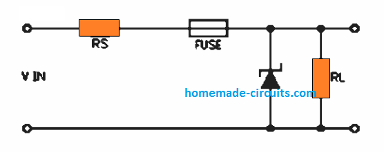
By joining a correctly rated Zener diode across the load, a fuse which is suitably rated to handle the intended load current for extended periods can be employed. In this situation, suppose the input voltage increases to an extent that exceeds the Zener breakdown voltage - will force the Zener diode to conduct. This will cause a sudden increase in the current blowing the fuse almost instantaneously.
The advantage of this circuit is that it prevents the fuse from blowing frequently and unpredictably due to its close fusing value to the load current. Instead, the fuse blows only when the voltage and current genuinely rises beyond a specified unsafe level.
Undervoltage Protection Circuit using Zener Diode
A relay and an appropriately selected zener diode are enough to create an accurate low voltage or under voltage cut off protection circuit for any desired application. The circuit diagram is presented below:
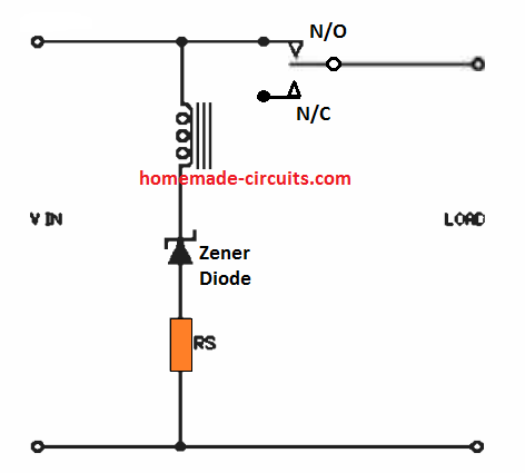
The operation is actually very simple, the supply Vin which is acquired from a transformer bridge network varies proportionately depending on the input AC variations. That implies, if suppose the 220 V corresponds to 12 V from the transformer, then 180 V should correspond to 9.81 V and so on. Therefore, if 180 V is assumed to be the low voltage cut off threshold, then selecting the zener diode as a 10 V device will cut off the relay operation whenever the input AC drops below 180 V.
Yes, I have thought about using the TL431 but the problem is that the minimum voltage is 2.5v and I need it to at least start stabilizing from 700mv
In that case you can try one of the circuits explained in the following article:
https://www.homemade-circuits.com/low-dropout-5v-12v-regulator-circuits-using-transistors/
Hello, good afternoon, I am a faithful follower of the site, I want to ask you if you have or can build a circuit to set a voltage, a Zener diode type but variable from maybe 500mv to 5 or 10vcc…thank you very much in advance.
Thank you Carlos, if you want a variable zener diode type voltage regulator circuit, then you can try the following concept:
https://www.homemade-circuits.com/explaining-programmable-shunt-regulator/
Good morning, Engineer Swagatam. Thanks for your teachings.
Kindly recommend to me a value of the Zener diode and the associated resistor required for a low voltage protection in an inverter with a battery voltage of 12V.
The Zener diode is to be used with an OP-AMP, LM 741.
Hi Obademi,
How is the opamp configured, is it like a comparator? Do you want a zener diode to provide the reference voltage for the opamp?
Great post and great website!
Thank you!
Hi Swagatam,
Firstly I want to thank you for what you are doing. I am Marcel from South Africa.
I need to make a circuit nearly the same as your Zener diode circuit for over voltage protection.My application is using the 24V on a truck as my off position, and when the truck starts that voltage go to 28V I would use a 27V Zener. So at 24V the relay must not pull in it must only pull in at 27V.
Would appreciate your assistance.
Regards
Marcel
Thank you Marcel,
yes you can connect a 27V or a 26V zener diode in series with the relay coil so that it activates only once eh input DC exceeds 27V
Hello Swagatam,
I am trying to design a Zener controlled series pass regulator for my Solar system. I have 3 x 230W panels in series that generate on a normal sunny clear day 95VDC, ~33V per panel with max current of ~8Amps. My Charge Controller has a Max input of 100VDC. On very bright cloudy days the Voltage exceeds the input ~102VDC and reports an error and the Charge Controller stops working until the Solar panels are turned off with my Circuit Breakers.This is not a good situation as I have to be there to power off the panels. I would like to see a cct that when 102VDC is applied at input the cct clamps or controls the output to 99VDC keeping it under the max on those really bright cloudy days. So when the input is below the 100VDC it passes all the current of 8Amps and only operates to limit the output when the input exceeds 99VDC. I realise that I will have to have some High Power Transistors or FETs (with heat sinks) to handle the max of 8Amps charge current (which is only at that level when Batteries are low in the morning and reduces as they become fully charged) If you have a cct that I could try or modify to suit my purpose. What a great site you have created, with so many great cct ideas. Thanks Paul in Rockhampton, Queensland, Australia.
Thank you Paul for posting this useful question, and glad you liked my site.
 " alt="solar current controller regulator using stabilized pass transistor" />
Here’s a simple solution that you can apply for the required results:
TRA can be any 150 V 20 amp power transistor such as 2N6341 or MJH11022
Datasheet: https://www.onsemi.com/pub/Collateral/MJH11017-D.PDF
TRB can be a MJE15030G
TRC and RB can be ignored and removed since current control is not required in this application.
If a Darlinton BJT is used like the MJH11022, then the RA can be around 10K 1 watt, for normal power BJT this could be calculated as:
RA = 102 – 95 / 8 = 0.875 ohms or simply 1 ohms
wattage = 102 – 95 x 8 = 56 watts or 60 watt.
The zener can be a 90 V zener and the preset a 10k preset, which can be used for fine-tuning the cut-off threshold.
Let me know if you any further doubts or questions
Mr Swagatam, Thank you for your speedy reply, I was thinking you have so many replies to respond to along with your career, that it may have been some time before I saw a reply.
I had looked at this cct and was thinking it would be a good one to modify, but was unsure just what I had to do to make what I needed. I will use the TrA MJH11022 and TrB MJE15030G as you suggest and remove TrC and RB. I will have to buy some special wire make the 1 ohm 60W resistor.
The last time I checked suppliers, the highest Zener diode voltage available at this time is 75V. I saw your other cct adding a number of zeners in series to make any voltage needed. So I will join a number of zeners them to make approx 90V, I worked out that the current through the VRA when the Zener voltage is reached will be very low, then the zeners could be 1/2W. The adjustable VRA should then allow me to trim the output to 98-99V if the input V is over 99V. I am so pleased that you have offered me your expertise in resolving my solar problem. I will start to get the parts together and begin to build. I will need to make 4 units as I have 2 sets of 3 x 250W in series and they are connected in parallel to give me the max input current of 16Amps per Charge Controller. To explain, each group of 2 (3 x250W) are then connected to 2 Circuit Breakers then connected to 1 of 2 Charge Controllers, so 4 of your ccts are needed. Each Charge Controller charges 2 x 140AH AGM in series giving me 24V, then paralleled with the 2nd set of AGM’s, so I effectively have 280AH at 24V for my Inverter. Regards Paul
Thank you Paul, I am glad to help.
I think there’s a problem with my previous RA calculation. It should be actually in the following way:
RA = 0.7hFE / Output Current
RA = 0.7 x 20 / 8 = 1.75 Ohms
Since the BJT is an emitter follower, the wattage will be 0.7 x 8 = 5.6 watts or simply a 10 watt resistor will do the job.
According to me this result should be the correct one.
In case the pass BJT is a Darlington then the RA resistor value becomes rather immaterial due to the high gain of a Darlington pair, and therefore even a 1k 5 watt should work nicely.
Thank you very much for the invitation :). Best wishes.
PS: How are you? I am from France 🙂
good afternoon sir,i have a zener diode after thorough checking of it does not give up to 1v,why is it like that sir?
You zener may be faulty, or you may be checking it wrongly.
Very useful for zener diode circuit explained thank you sir, sir 350 w,ir2153 ic smps power supply short circuit protection,how to add the circuit please sent circuit diagram sir, thank you
Thanks Kumar, however, Sorry I d not have that circuit with me at this moment!
Thank you.
You are welcome!
your very wonderful sir.
Excellent post.
But sir, am a beginner in electronics, and am looking for how a transistor functions in different configurations, including CB, CC, CE mode.
I’ll really appreciate it if u help me please.
Thank you Andrew, Glad you are loving my site, you can find the required details under this category:
https://www.homemade-circuits.com/category/electronic-devices-and-circuit-theory/page/4/
https://www.homemade-circuits.com/category/electronic-devices-and-circuit-theory/page/3/
Hi friend !
Distinctive material, useful read.
shapely quest.
Thank you friend, appreciate your feedback!