A practical electronics engineering resource focused on tested circuit projects, clear theory explanations, design calculations and real world troubleshooting support for students, hobbyists, and professionals.
Questions Answered with Practical Working Solutions
Backed by more than two decades of hands on circuit design experience, reader questions posted in the comments are reviewed and answered personally. Wherever necessary, circuit corrections, design improvements, and verified working solutions are provided to ensure accuracy and reliability.
How To Use This Website
- Start with the Electronics Tutorials section if you are new to circuit design.
- Explore application based projects to find ready to use circuits.
- Read the comments for practical tips, corrections, and reader discussions.
- Post your questions to get guidance and improvements where needed.
Learn Electronics Step By Step
Electronics Tutorials

Foundational tutorials explaining electronic concepts, calculations, and working principles in a simple and practical way.
Semiconductor Theory
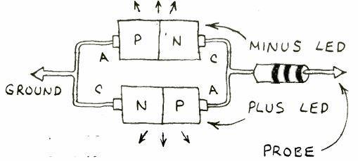
Detailed explanations of semiconductor devices and circuit theory with practical examples and applications.
Arduino and Microcontrollers

Arduino programming tutorials and microcontroller based automation projects with complete circuit details.
IC 555 Timer Circuits
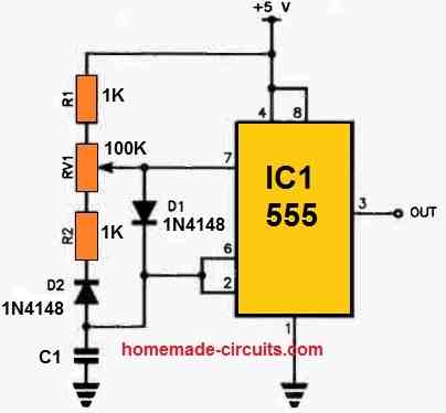
Classic and modern IC 555 timer circuits explained with calculations, diagrams, and application ideas.
Power Electronics and Energy Systems
Inverter Circuits
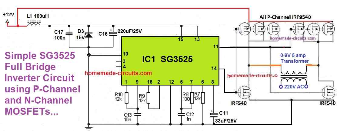
Designs that convert DC power into 220V AC with explanations ranging from basic to advanced sine wave systems.
Battery Charger Circuits
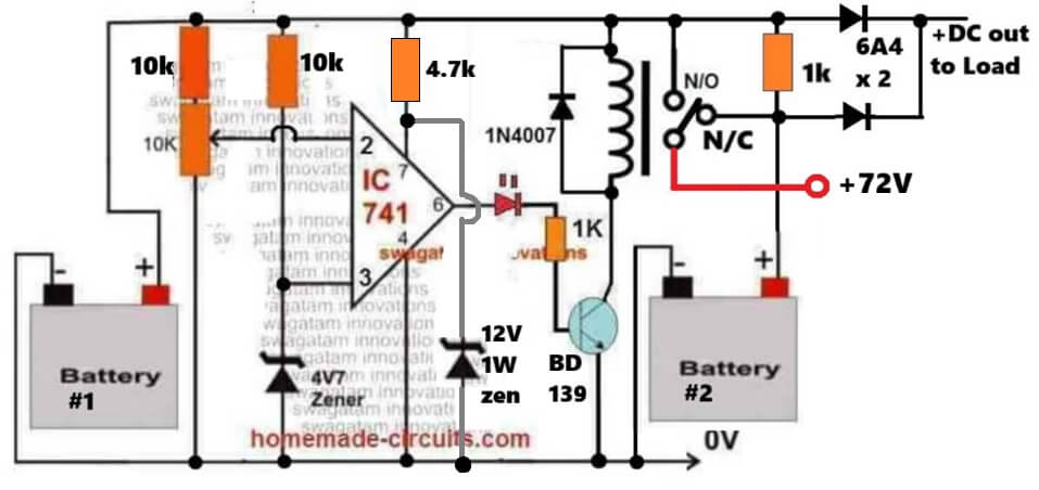
Controlled battery charging circuits covering lead acid, lithium, and industrial battery systems.
Power Supply Circuits
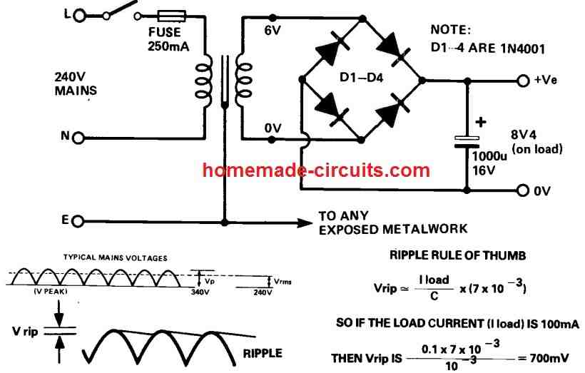
Fixed and variable voltage power supply projects for workbench testing and embedded applications.
Solar Controllers
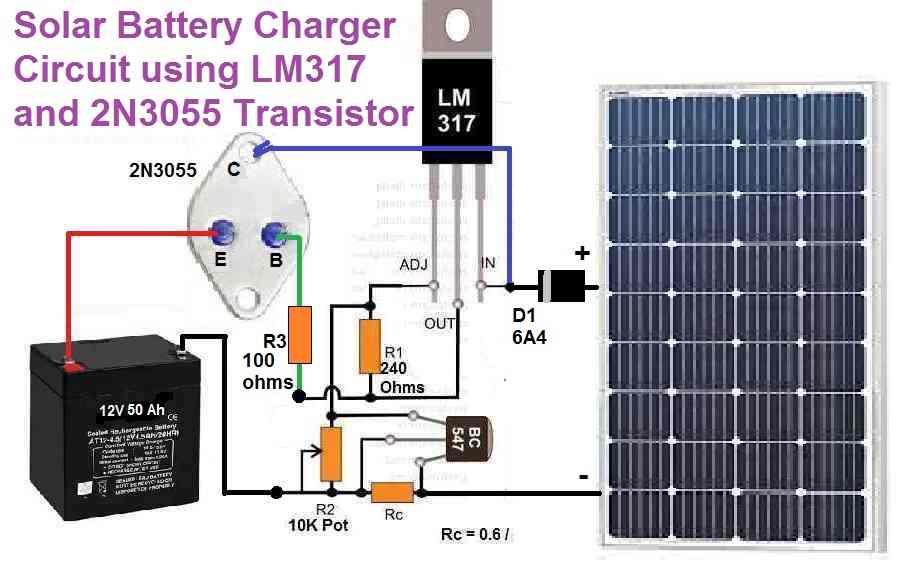
Solar charge controllers and renewable energy projects using PWM, MPPT, and microcontroller techniques.
Application Based Electronic Projects
Home Electrical Projects
Electronic circuits designed to enhance safety, automation, and efficiency in home electrical systems.
Industrial Electronics
Control and automation circuits used in industrial machinery and process systems.
Automobile Electronics
Automotive electronic projects for lighting, safety, and performance enhancements.
Motor Control Projects
Speed and torque control circuits for DC and AC motors used in home and industrial applications.
LED and Lighting Projects
Decorative and functional LED lighting circuits including dimmers, chasers, and drivers.
Remote Control Circuits

Wireless and IR remote control circuits for convenient device operation from a distance.
Specialized and Utility Circuits
Wireless and GSM Projects
Wireless control and GSM based communication projects for monitoring and automation.
Meters and Testers

Hand-built electronic meters and testers useful for diagnostics and troubleshooting.
Timer and Relay Circuits
Delay timers and relay switching circuits for automation and protection applications.
Learning Through Discussion
A lot of the circuits here slowly get better through questions and discussions in the comments. Readers point out real world problems, ask for small changes, or request clarifications, and over time this back and forth helps turn the designs into more reliable and practical working circuits.
Try and Test Circuits Online
To help readers better understand how circuits behave, this website also includes a simple online circuit simulator. It can be used to visualize basic circuit operation, test component changes and explore circuit behavior before building it practically.

Recent Community Discussions
Latest questions, answers, and circuit improvements discussed by readers and the author.
This USW weapon relies on an ear-piercing sound to cause pain to the target.... without an audible sound, it cannot…
Sure, here's a simple VFD design without using microcontrollers. Of course it is just a crude version, which can be…
Thanks for your kind words and detailed explanation. Yes, I agree, automation using sophisticated chips has become a child's play…
how to make inaudible version of this?
I beleive you have answered my question even if I did not express it clearly. For most small motors shaded…


Common Problems Addressed
- Circuits that do not work as expected after assembly.
- Confusion about component values and calculations.
- Improper power supply or overload issues.
- Noise, heating, and instability in practical circuits.
- Modification of existing circuits for custom requirements.
Note: All circuits are provided for educational and experimental purposes. Readers are advised to follow proper safety precautions while working with mains voltage and high power circuits.
Questions & Answers
With a CD4060, I want to build an on/off timer for a relay ranging from 3 hours down to a few minutes, such that by changing a switch between the output pins of the CD4060 and also a potentiometer connected to pin 10, the time values can be changed. Can I connect the output of each Q one by one to the collector of a separate transistor, connect the emitters together to the relay coil or to a transistor for turning on the relay, and use a multi-position switch to select one of the bases of the transistors connected to the Q outputs? Is this method correct?
Yes, your method is ok and will work. You can take the help of the software to calculate the parts vaalues:
https://www.homemade-circuits.com/ic-4060-calculator/
Hello Swagatam NAMASKAR
I am small manufaturer of Agri based product like preventers, timers since 1996. For that Still i am using 440V/10.5V -/ 250mA Transformer. Now I want to avoid transformers because of price hick. Can you suggest me transformer less power supply or Low cast SMPS (prefered) for my product can be is isolated (prefered) or non isolated,
Thank you
With regards
Pattabi Raman
kanagamani.tvm(at)gmail.com
Hello Raman,
Thanks for your question.
I would suggest you the following simple yet reliable SMPS for your specific application:
https://www.homemade-circuits.com/220v-smps-cell-phone-charger-circuit/
Let me know if you have any further questions…
Thanks for your replay
How can i use this for 440V AC input.I have no nutral connection in my product. Suggest a circute for 300V – 440V AC input .
Thanks
In that case you may have to design your own smps, using the following calculator tool:
https://www.homemade-circuits.com/forward-type-smps-transformer-lc-calculator-tool/
Happy sunday sir I wish you more to witness, sir I want you to explain how I can use pin 3 of SG3524N IC connected to another 2 ic making it 3 with the master ic?.
And how it work?, with step by step calculation guideline.
Good Day Micheal:
To sync three sg3524 chips you tie pin 3 of the master to pin 3 of both slaves so the master’s oscillator pulse forces a reset and locks them in phase. For calculations the slave needs to run about 10 percent slower so the master takes control. Datasheet rule is make the slave timing capacitor half the size of the master cap and use a timing resistor about 2.2 times larger. Or if they are right next to each other on the board you can just share a single capacitor by linking all their capacitor pins together and leave the slave resistor pins disconnected while tying pin 3s.
goodday sir,thankyou, if I may ask that are the 2 slave will have their independent mosfetdriver,mosfet and transformer each?.
secondly, is it only timing resistor am I going to sold to the slave’s or timing capacitor?.
okay sir,if I can get you right you mean I don’t have to apply timing resistor too those slave?.just only timing capacitor?.
secondly, I think I can use this setup for 3phase inverter or what do you think about it?.is it right to gain 3 phase from it?.
Yeah exactly, if you use the shared capacitor shortcut then you leave the slave timing resistor pins completely empty and just share that one cap but if you do the separate component way then you still need those modified resistors on the slaves. Regarding your second question, no you cannot use this setup for a true 3-phase inverter because syncing pin 3 locks all the chips completely in phase at zero degrees meaning they all fire at the exact same time whereas a 3-phase inverter needs 120 degrees of phase separation between the legs, so this sync trick is only good for paralleling or single phase, not for 3-phase.
Thanks Micheal, Yes, each ic outputs its own drive signals so yes the two slaves will have their own mosfet drivers mosfets and transformers for each power stage. For your second question, in the standard way you solder both a timing capacitor and a timing resistor to each slave using those modified values we talked about, but if you use that shared capacitor shortcut you only wire the shared cap across them and leave the slave timing resistor pins totally empty.
Goodmorning sir,thanks for yesterday pls sir I need a step by step guide on how to calculate calculate Rt and Ct timing for my inverter oscillator using SG3524N IC running at 50Hz frequency.
Good Morning Michael,
You can find all the related details, under the following article:
https://www.homemade-circuits.com/ic-sg3525-calculator/
good evening sir, please I need diagram of battery discharge circuit diagram.
Good Morning Michael, you can try the following concept:
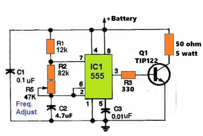
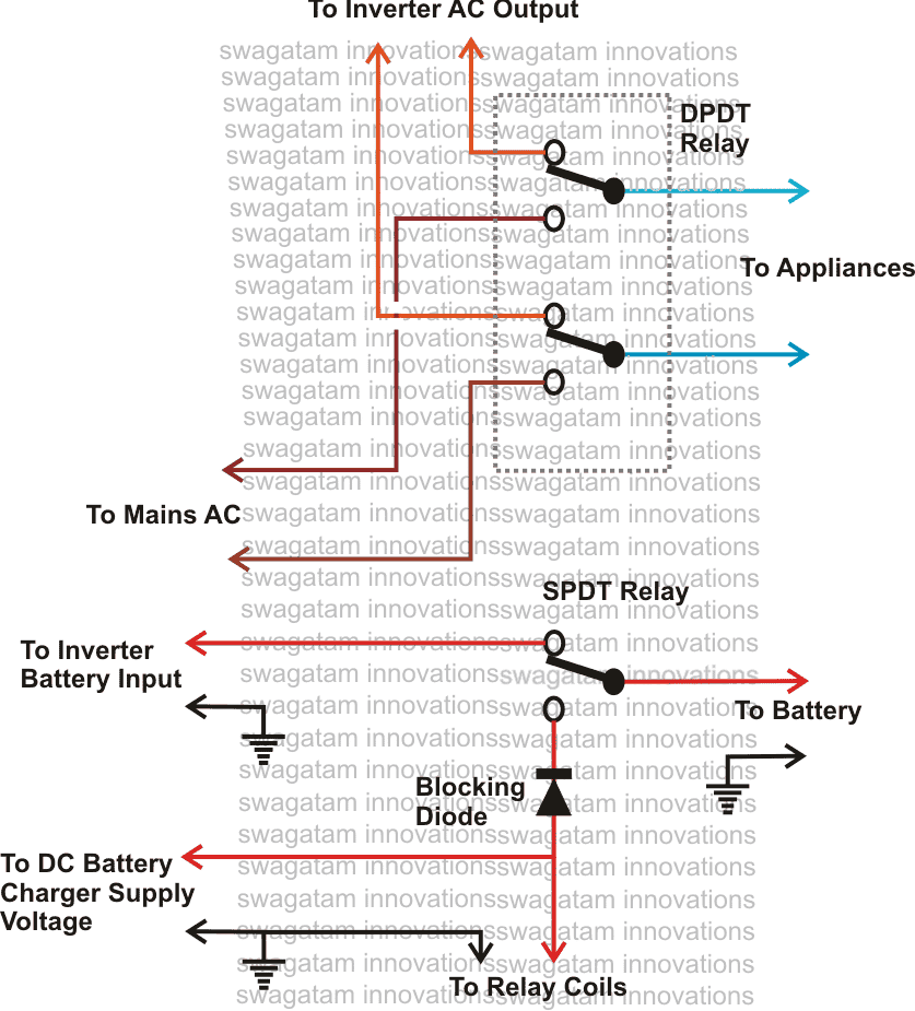
okay sir,but one thing I want to ask is that, assuming am working with 12v inverter system and I want to charge back the battery at low battery stage,will I use that dc voltage to energise the relay coils of relay 1 and 2?.
as I said earlier that am working with 12v system, and we all know that 12v lithium battery will fully charged at 12.6v, the dc that want to energise all the relay coils now will it be 12.6v? according to the lithium ion battery charging state.
Yes, that’s correct, all the relay coils will use the 12V DC from the charger to activate and changeover to battery charging mode, and output AC Grid mode.
if I get what you’re saying sir is that I will have to connect all the coil of the relay to each other, I mean the first relay and the second relay coil and connectthe dc battery chargerto it. or is that not what you mean?.
Yes, connect all the relay coils in parallel with a single parallel freewheeling 1N4007 diode, and then connect all these parallel elements with battery charger DC supply.
Hello sir.
I need a capacitor of about half a farad.
But this kind of capacitor is very expensive.
How can I multiply the capacitance with a circuit?
Do these kinds of circuits have positive and negative terminals?
And how should it be used?
Hello Mazlom,
Yes, you can use a transistor capacitance multiplier. A circuit with an NPN transistor, a resistor, and a small capacitor multiplies capacitance by the transistor’s current gain. Yes, it has positive and negative terminals since it is polarized. You connect it along a DC power line to filter ripple, but it cannot replace a real 0.5F supercapacitor for bulk energy storage because it cannot supply heavy currents.
Hello sir,
Thank you for your response.
Is it suitable with a transistor circuit or with an op-amp?
From how many volts to how many volts will these circuits work, and by how many times can they multiply the capacitor?
Under what conditions do they not perform well?
https://imgur.com/a/IJOKHoO
Mazlom, transistor version is better, because you can use higher voltage also, depending on the transistor VCE rating:
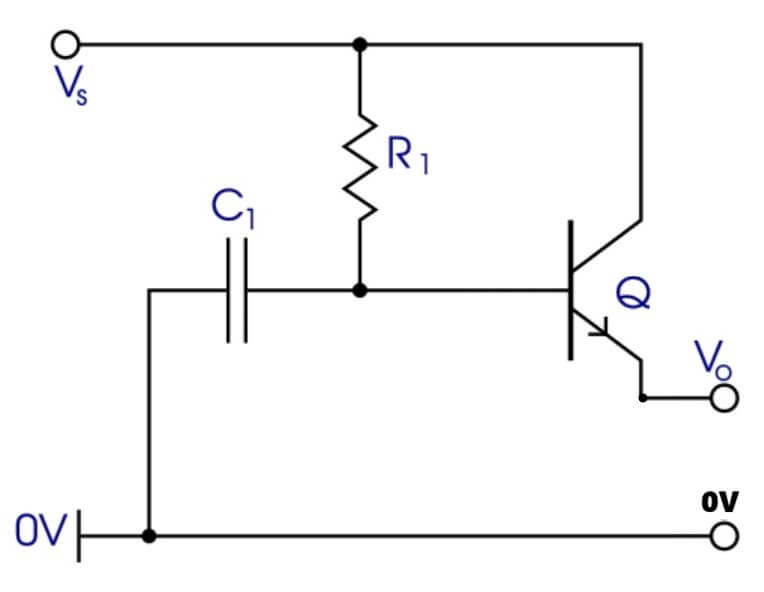
The multiplied capacitance is roughly C * beta (where beta is the DC current gain of the transistor).
Hello sir,
The Vs shouldn’t be connected to anything, right?
Is a transistor with lower gain more suitable for this capacitance multiplier?
Hello Mazlom,
The Vs must be connected to the unfiltered DC input, for example to a bridge rectifier’s +DC. The emitter will go to the positive of the output circuit which needs the filtered DC. Lower BJT gain will cause lower level of filtration, and higher ripples.
goodmorning, take tou for yesterday sir,please I want to ask that how can I make an automatic changeover for my 12v inverter circuit,in the extent that when there’s grid supply it will charge on it own, and when the grid off it will switch to inverter mode automatically?. thank for your support.
Hi Michael, you can try this conecpt:
Goodday sir, I want to ask that is it compulsory to put 6capacitor in parallel to make a input filter for 12v system using SG3524N inverter oscillator?.
No, you can use any number of capacitors as long as the total capacitance and ripple current rating are enough to handle the input load and switching spikes of the 12V inverter. Multiple capacitors are usually just used in parallel to share the ripple current, reduce equivalent series resistance (ESR), and fit the physical space better.
👍 sir,thank you I really appreciate you God bless you sir. one more thing,that dpdt relay coil am I going to abaddon it or energise it.or how do you think 🤔 I can fo it sir, and is the relay are meant for only ac voltage or for both ac and dc voltage?.
Thank you Michael, all the relay coils in the previous relay changeover circuit will need to be powered from the battery charger supply DC. Relay contacts can handle both AC and DC supplies, but the ratings may differ…
good day sir, I hope all is good, please sir I need your help I need a good working Sg3524 with feedback oscillator for inverter 12volts system thank you very much sir
Hi Solomon, you can try the concepts explained in this article:
https://www.homemade-circuits.com/inverter-circuit-with-feedback-control/
Hello! Do you have any good RF power amplifiers for the 35 MHz band, approximately 0.5 W, operating voltage around 12 volts?
Hi, I think you can get a 30 MHz design in the following article, which might need some modifications to be able to amplify a 35 MHz signal:
https://www.homemade-circuits.com/wideband-amplifier-circuits/
hello goodmorning, goodevening, and good afternoon in anywhere you can saw this message, I’m one of this class and am glad to be here.
my greetings also goes to our boss may God bless him.
please sir I need a well drawn circuit diagram for inverter oscillator project with a voltage regulator. please 🙏 I will be so glad 😊 if I can have it.and that reminds me sir that the ic must be sg3524n or sg3525 ic
alright, thanks boss I will do that
Good evening Michael,
If you search for “SG3525” in the top search box, you can get many good options which will fulfil your requirement…
hi sir,,it’s MdKen,,than you so much..
pls can you help me with a high end 9v powered 3band eq onboard preamp circuit design I can put in my ibanez sr505 bass guitar…I bought a it cheap but it was sabotaged …
the guitar uses 2 passive pickups
Hi Md.
You can try the first circuit from the following article:
https://www.homemade-circuits.com/10-band-graphic-equalizer-circuit-for/
For further doubts, you can feel free to comment under the above article..
On my old motorcycle, I’ve added a piezo beeper on each of the front turn indicators: that’s allows me to not forget them on. Puttin one on each was the easyest way to make it works.
I’ve done the same on my new one, but this new bike flashes the turn indicators to signal that the keyless system is engaged, resultin in a lot of noise.
What would be the simplest, smaller circuit to make a beeper sounds when one indicator is on, but not when both of them are on?
I think the easiest way is to use only one common buzzer for all the indicators, meaning if any of the indicators is turned ON, the buzzer sounds. This will also solve the noise issue during the keyless retry. What do you think?
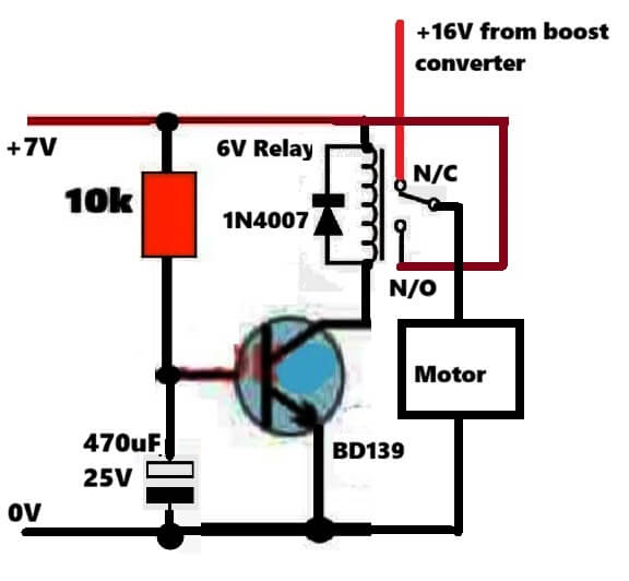
I have a water pump bought cheaply at a nearby electronic stores. Its voltage and amp rating is not known but it runs nicely at 7.4V 3A. However, every time I need to start it, I need 16.8V to kickstart it and then I can run it with my 7.4V Li-ion pack. Is there any circuit that makes sure that the motor doesn’t need the initial 16.8V of power to start up and it can run with 7.4V throughout? Thanks in advance
Actually the pump is taking 16.8V kick just to break that initial tight motor friction. Best solution is put one cheap MT3608 or XL6009 boost converter module set to 16.8V, along with one simple 1-second delay relay or 555 timer circuit. So when you switch ON, then it gives 16.8V boost for just 1 second to kickstart the motor, then relay immediately switches line to direct 7.4V battery pack for normal running!
Is it possible you share the circuit diagram here
You can try this configuration: